7A2-22 TRANSMISSION CONTROL SYSTEM (AW30 –40LE) (V6 3.5L)
TRANSMISSION DATA
ITEM UNIT ENGIN RUNNING AT IDLE
Current Gear 1 st/2 nd/3 rd/4 th 1 st
Target Gear 1 st/2 nd/3 rd/4 th 1 st
Vehicle Speed km/h 0 km/h
AT Output Speed (Automatic Transmission) RPM 0 RPM
AT Input Speed (Automatic Transmission) RPM 675�725 RPM
Engine Speed RPM 675�725 RPM
Throttle Position Sensor Signal % 0.00�7.00%
AT Oil Temperature (Automatic Transmission) �C Depends on conditions
TCM Status Transfer Low /Transfer High Transfer HI
Desired PC Solenoid Pressure (STH) kPa 34.3�97.0 kPa
Desired PC Solenoid Current (STH) mA 835�1020 mA
PC Solenoid Actual Current (STH) mA 835�1020 mA
Gear Ratio : 1 Depends on uper hood
TCC Slip Speed RPM 0 RPM
Shift Position Actual P/R/N/L/2/3 P
Inhibitor Switch P/R/N/L/2/3 P
Transmission Check Light On/Off Off
AT Oil Temperature Lamp (Automatic
Transmission) On/Off Off
3 rd Start Lamp On/Off Off
Power Lamp On/Off Off
Shift Solenoid S1 On/Off On
Shift Solenoid S2 On/Off On
Shift Solenoid S3 On/Off Off
Diag Switch Condition On/Off Off
Power Switch On/Off Off
Brake Switch On/Off Off
Cruise Switch On/Off Off
4L Signal On/Off Off
3 rd Start Switch On/Off Off
Coolant Temperature �C Depends on conditions
Torque Request (timing Retard) �CA 0 �CA
Garage Shift Mode On/Off Off
CAN TPS % 0.00%
CAN Signal Valid Counter (ECM)
— 0 � 255
CAN Signal Valid Counter (TCM) — 0 � 255
ON-VEHICLE SERVICE (JR405E) 7A3-3
Cold Level
The vehicle must not have been driven so that the
temperature reaches around 20�C (68�F) before the
cold level check is made.
1. Park the vehicle on a level surface.
2. Apply the parking brake firmly.
3. Start the engine and allow it to warm up.
The engine coolant temperature gauge needle
should be midway between the “C” mark and “H”
mark.
4. Let the engine run at idle.
Move the select lever slowly through all the gea
r
ranges.
Stop in each range just long enough for the
transmission to engage.
5. Return the select lever either “P” or “N”.
6. Remove the ATF level dipstick.
7. Wipe the dipstick clean with a paper towel.
8. Reinsert the dipstick and wait several seconds.
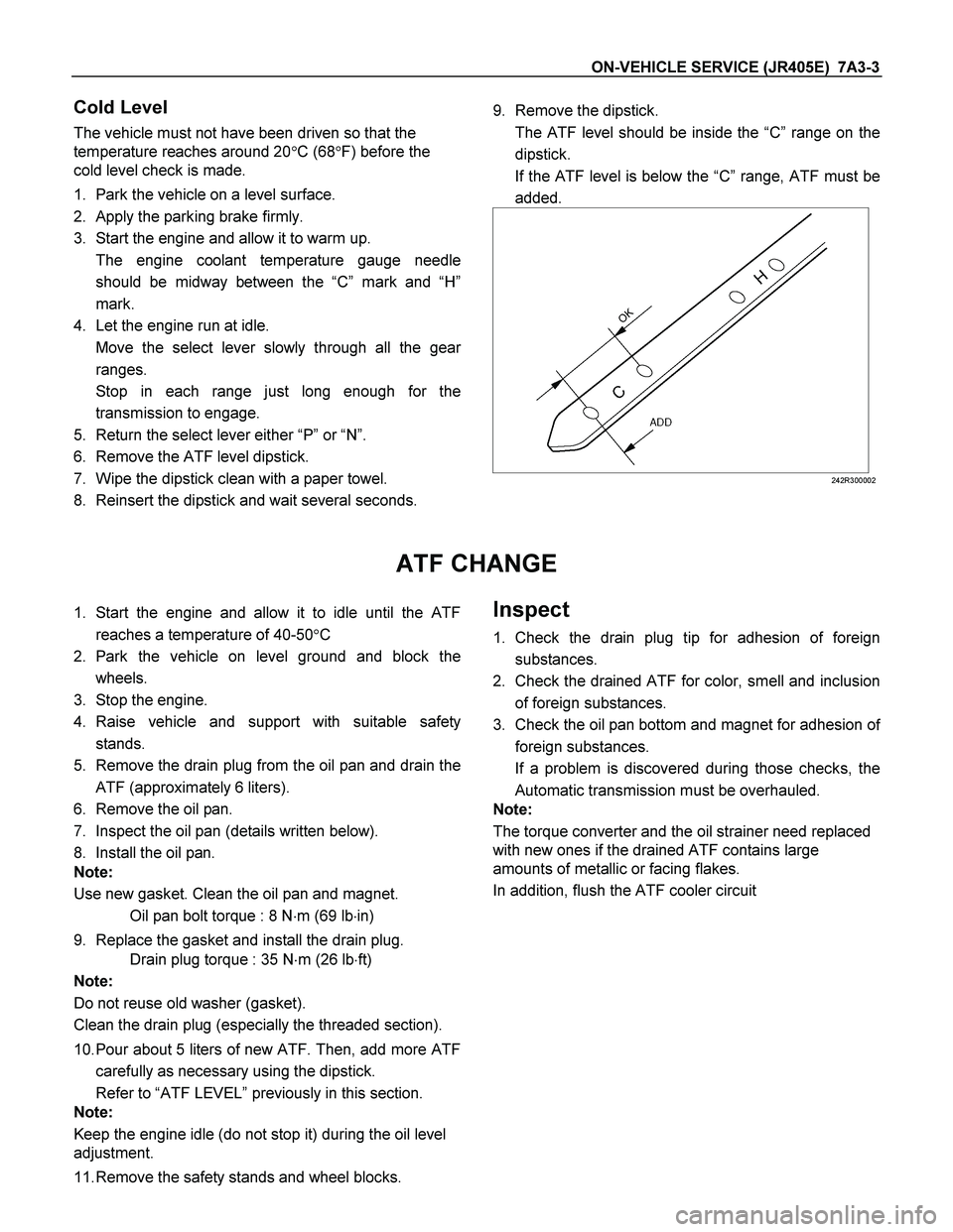
9. Remove the dipstick.
The ATF level should be inside the “C”range on the
dipstick.
If the ATF level is below the “C” range, ATF must be
added.
242R300002
ATF CHANGE
1. Start the engine and allow it to idle until the ATF
reaches a temperature of 40-50�C
2. Park the vehicle on level ground and block the
wheels.
3. Stop the engine.
4. Raise vehicle and support with suitable safety
stands.
5. Remove the drain plug from the oil pan and drain the
ATF (approximately 6 liters).
6. Remove the oil pan.
7. Inspect the oil pan (details written below).
8. Install the oil pan.
Note:
Use new gasket. Clean the oil pan and magnet.
Oil pan bolt torque : 8 N�m (69 lb�in)
9. Replace the gasket and install the drain plug.
Drain plug torque : 35 N�m (26 lb�ft)
Note:
Do not reuse old washer (gasket).
Clean the drain plug (especially the threaded section).
10. Pour about 5 liters of new ATF. Then, add more ATF
carefully as necessary using the dipstick.
Refer to “ATF LEVEL” previously in this section.
Note:
Keep the engine idle (do not stop it) during the oil level
adjustment.
11. Remove the safety stands and wheel blocks. Inspect
1. Check the drain plug tip for adhesion of foreign
substances.
2. Check the drained ATF for color, smell and inclusion
of foreign substances.
3. Check the oil pan bottom and magnet for adhesion o
f
foreign substances.
If a problem is discovered during those checks, the
Automatic transmission must be overhauled.
Note:
The torque converter and the oil strainer need replaced
with new ones if the drained ATF contains large
amounts of metallic or facing flakes.
In addition, flush the ATF cooler circuit
 (V6 3.5L)
TRANSMISSION DATA
ITEM UNIT ENGIN RUNNING AT IDLE
Current Gear 1 st/2 nd/3 rd/4 th 1 st
Target Gear 1 st/2 nd/3 rd/4 th 1 st")