Page 142 of 4264
4A-6 PROPELLER SHAFT
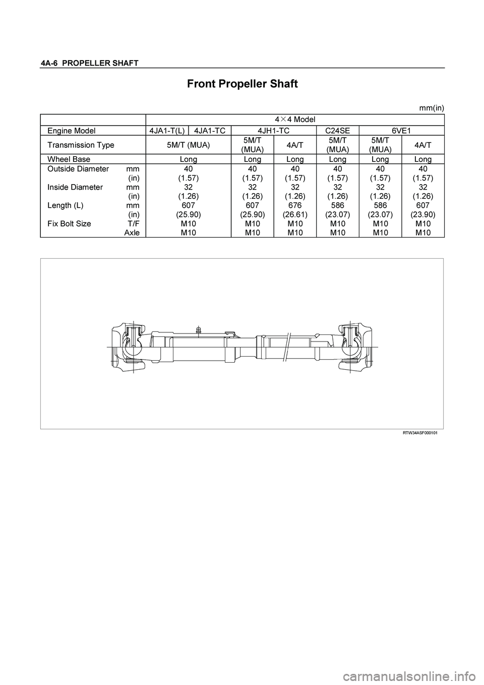
Front Propeller Shaft
mm(in)
4�
4 Model
Engine Model 4JA1-T(L) 4JA1-TC 4JH1-TC C24SE 6VE1
Transmission Type 5M/T (MUA) 5M/T
(MUA) 4A/T 5M/T
(MUA) 5M/T
(MUA) 4A/T
Wheel Base Long Long Long Long Long Long
Outside Diameter mm 40 40 40 40 40 40
(in) (1.57) (1.57) (1.57) (1.57) (1.57) (1.57)
Inside Diameter mm 32 32 32 32 32 32
(in) (1.26) (1.26) (1.26) (1.26) (1.26) (1.26)
Length (L) mm 607 607 676 586 586 607
(in) (25.90) (25.90) (26.61) (23.07) (23.07) (23.90)
Fix Bolt Size T/F M10 M10 M10 M10 M10 M10
Axle M10 M10 M10 M10 M10 M10
RTW34ASF000101
Page 144 of 4264
4A-8 PROPELLER SHAFT
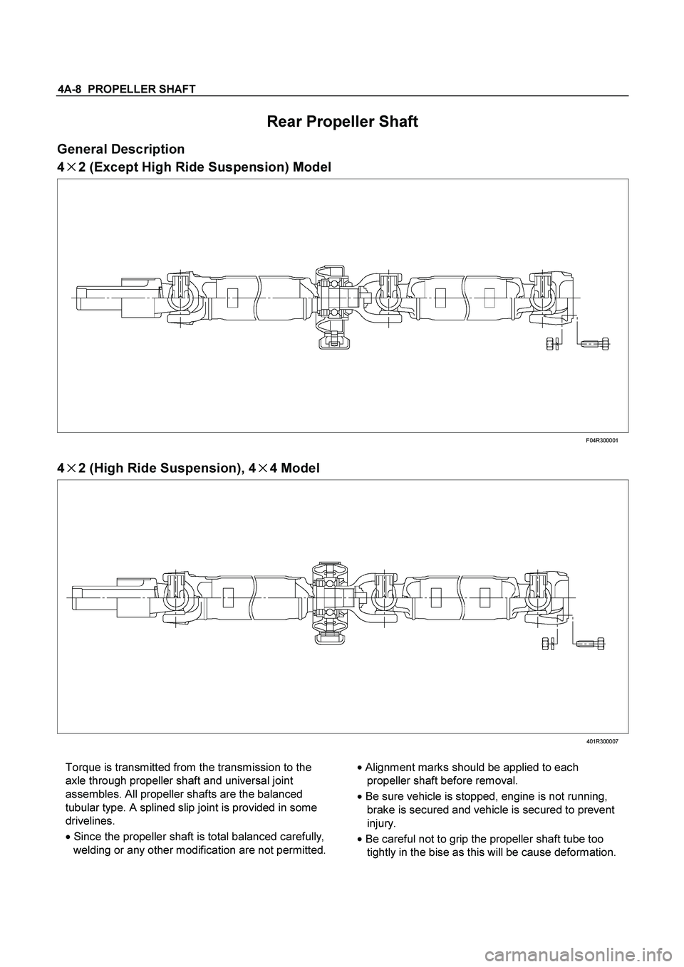
Rear Propeller Shaft
General Description
4�
�� �2 (Except High Ride Suspension) Model
F04R300001
4
�
�� �2 (High Ride Suspension), 4
�
�� �4 Model
401R300007
Torque is transmitted from the transmission to the
axle through propeller shaft and universal joint
assembles. All propeller shafts are the balanced
tubular type. A splined slip joint is provided in some
drivelines.
�
Since the propeller shaft is total balanced carefully,
welding or any other modification are not permitted. �
Alignment marks should be applied to each
propeller shaft before removal.
�
Be sure vehicle is stopped, engine is not running,
brake is secured and vehicle is secured to prevent
injury.
�
Be careful not to grip the propeller shaft tube too
tightly in the bise as this will be cause deformation.
Page 170 of 4264

4B-6 REAR AXLE
RECOMMENDED LIQUID GASKET
Type Brand Name Manufacture Remarks
RTV*
Silicon Base ThreeBond 1207B
ThreeBond 1207C
ThreeBond 1215
Three Bond
Three Bond
Three Bond
For Engine Repairs
For Axle Case
Repairs, T/M
Water Base ThreeBond 1141E Three Bond For Engine Repairs
Solvent ThreeBond 1104
BelcoBond 4
BelcoBond 401
BelcoBond 402 Three bond
Isuzu
Isuzu
Isuzu
For Engine Repairs
Anaerobic LOCTITE 515
LOCTITE 518 Loctite
Loctite All
* RTV : Room Temperature Vulcanizer
Note :
1. It is very important that the liquid gaskets listed
above or their exact equivalent be used on the
vehicle.
2. Be careful to use the specified amount of liquid
gasket.
Follow the manufacture's instructions at all
times.
3. Be absolutely sure to remove all lubricants and
moisture from the connecting surfaces before
applying the liquid gasket.
The connecting surfaces must be perfectly dry.
4. LOCTITE 515 and LOCTITE 518 harden upon
contact with a metal surface.
Do not apply LOCTITE 515 or LOCTITE 518
between two metal surfaces having a clearance
of greater than 0.25 mm (0.01 in). Poor
adhesion will result.
RECOMMENDED THREAD LOCKING AGENTS
LOCTITE Type LOCTITE Color Application Steps
LOCTITE 242
Blue 1. Completely remove all lubricant and moisture from the bolts and
the female threaded surfaces of the parts to be joined.
The surfaces must be perfectly dry.
LOCTITE 262
Red 2. Apply LOCTITE to the bolts.
LOCTITE 270
Green
LOCTITE 271
Red
3. Tighten the bolts to the specified torque.
4. Wait at least one hour before continuing the installation procedure.
Page 171 of 4264

REAR AXLE 4B-7
REAR AXLE ASSEMBLY
General Description
A03R300001
The rear axle assembly is of the semi–floating type in
which the vehicle weight is carried on the axle
housing .
The center line of the pinion gear is below the center
line of the ring gear (hypoid drive).
All parts necessary to transmit power from the
propeller shaft to the rear wheels are enclosed in a
banjo type axle housing.
The 220 mm (8.6 in) ring gear rear axle uses a
conventional ring and pinion gear set to transmit the
driving force of the engine to the rear wheels. This
gear set transfers this driving force at a 90 degree
angle from the propeller shaft to the drive shafts.
The axle shafts are supported at the wheel end of the
shaft by a double tapered roller bearing.
The pinion gear is supported by two tapered roller
bearings. The pinion depth is set by a shim pack
located between the gear end of the pinion and the
roller bearing that is pressed onto the pinion. The
pinion bearing preload is set by crushing a collapsible
spacer between the bearings in the axle housing.
The ring gear is bolted onto the differential cage with
12 bolts.
The differential cage is supported in the axle housing
by two tapered roller bearings. The differential and ring
gear are located in relationship to the pinion by using
selective shims and spacers between the bearing and
the differential cage. To move the ring gear, shims are
deleted from one side and an equal amount are added
to the other side. These shims are also used to
preload the bearings which are pressed onto the
differential cage. Two bearing caps are used to hold
the differential into the rear axle housing.
The differential is used to allow the wheels to turn at
different rates of speed while the rear axle continues
to transmit the driving force. This prevents tire
scuffing when going around corners and prevents
premature wear on internal axle parts.
The rear axle is sealed with a pinion seal, a seal at
each axle shaft end, and by a liquid gasket between
the differential carrier and the axle housing
Page 207 of 4264
REAR AXLE 4B-43
TROUBLESHOOTING
Refer to this Section to quickly diagnose and repair
rear axle problems.
Each troubleshooting chart has three headings
arranged from left to right.
(1) Checkpoint
(2) Trouble Cause
(3) Countermeasure
This Section is divided into five sub-sections:
1. Abnormal Rear Axle Noise
1) Noise when the engine is driving the vehicle
2) Noise when the vehicle is coasting
3) Intermittent noise
4) Noise when the vehicle is turning
5) Constant noise
2. Vibration
3. Oil Leakage
1) Differential carrier leakage
2) Axle case leakage
3) Axle case to inside hub leakage
4) Axle case to inside brake drum leakage
4. Power Not Being Transmitted to the Wheels
(Propeller Shaft Operation is Normal)
Page 208 of 4264
4B-44 REAR AXLE
1. ABNORMAL REAR AXLE NOISE
1) Noise when the Engine is Driving the Vehicle
Checkpoint Trouble Cause Countermeasure
Replenish the gear oilInsufficient gear oil NG
Differential side bearingAdjust the differential side
bearing preload
Replace the drive pinion
bearings
Adjust the drive pinion bearing
preload
Replace the gear oil
Loose differential side
bearings
Worn drive pinion bearings
Loose drive pinion bearings
Wrong or poor grade gear oil
Drive pinion to ring gear
backlash
Drive pinion end play
Adjust the backlashToo much or too little backlash
Continued on the next pageOK OK
NG NG NG NG NG
OK
OK
Rear axle gear oil
Replace the differential side
bearingsWorn differential side bearings NG
Page 223 of 4264
FRONT WHEEL DRIVE 4C1-3
MAIN DATA AND SPECIFICATIONS
FRONT AXLE AND DIFFERENTIAL
Ring gear size mm (in) 194 (7.6)
Axle tube
Type It consists of the duce, a cast iron housing and the Axle tube.
Gear type Hypoid
Gear ratio (to 1) 4.100, 4.300, 4.555, 4.777, 5125
Differential type Two pinion
Specified gear oil (APL grade) GL-5
Oil capacity liter 1.4
(US/UK gal.) (0.4/0.33)
Axle shaft type Constant velocity joint (Birfield joint type and double offset joint).
FRONT PROPELLER SHAFT mm(in)
4�
4 Model
Engine Model 4JA1-T(L) 4JA1-TC 4JH1-TC C24SE 6VE1
Transmission Type 5M/T (MUA) 5M/T
(MUA) 4A/T 5M/T
(MUA) 5M/T
(MUA) 4A/T
Front Axle 194 mm �
�
�
�
�
Outside Diameter mm 40 40 40 40 40 40
(in) (1.57) (1.57) (1.57) (1.57) (1.57) (1.57)
Inside Diameter mm 32 32 32 32 32 32
(in) (1.26) (1.26) (1.26) (1.26) (1.26) (1.26)
Length (L) mm 607 607 676 586 586 607
(in) (23.90) (23.90) (26.61) (23.07) (23.07) (23.90)
Fix Bolt Size T/F M10 M10 M10 M10 M10 M10
Axle M10 M10 M10 M10 M10 M10
Page 226 of 4264

4C1-6 FRONT WHEEL DRIVE
RECOMMENDED LIQUID GASKET
Type Brand Name Manufacture Remarks
RTV*
Silicon Base ThreeBond 1207B
ThreeBond 1207C
ThreeBond 1215
Three Bond
Three Bond
Three Bond
For Engine Repairs
For Axle Case
Repairs, T/M
Water Base ThreeBond 1141E Three Bond For Engine Repairs
Solvent ThreeBond 1104
BelcoBond 4
BelcoBond 401
BelcoBond 402 Three bond
Isuzu
Isuzu
Isuzu
For Engine Repairs
Anerobic LOCTITE 515
LOCTITE 518 Loctite
Loctite All
* RTV : Room Temperature Vulcanizer
Note :
1. It is very important that the liquid gaskets listed above or their exact equivalent be used on the vehicle.
2. Be careful to use the specified amount of liquid gasket.
Follow the manufacture's instructions at all times.
3. Be absolutely sure to remove all lubricants and moisture from the connecting surfaces before applying
the liquid gasket.
The connecting surfaces must be perfectly dry.
4. LOCTITE 515 and LOCTITE 518 harden upon contact with a metal surface.
Do not apply LOCTITE 515 or LOCTITE 518 between two metal surfaces having a clearance of greater
than 0.25 mm (0.01 in). Poor adhesion will result.
RECOMMENDED THREAD LOCKING AGENTS
LOCTITE Type LOCTITE Color Application Steps
LOCTITE 242
Blue 1. Completely remove all lubricant and moisture from the bolts and
the female threaded surfaces of the parts to be joined.
The surfaces must be perfectly dry.
LOCTITE 262
Red 2. Apply LOCTITE to the bolts.
LOCTITE 270
Green
LOCTITE 271
Red
3. Tighten the bolts to the specified torque.
4. Wait at least on hour before continuing the installation procedure.
 Checkpoi")
 Noise when the Engine is Driving the Vehicle
Checkpoint Trouble Cause Countermeasure
Replenish the gear oilInsufficient gear oil NG
Differe")
 194 (7.6)
Axle tube
Type It consists of the duce, a cast iron housing and the Axle tub")