2004 ISUZU TF SERIES ABS
[x] Cancel search: ABSPage 2684 of 4264
6E–108 ENGINE DRIVEABILITY AND EMISSIONS
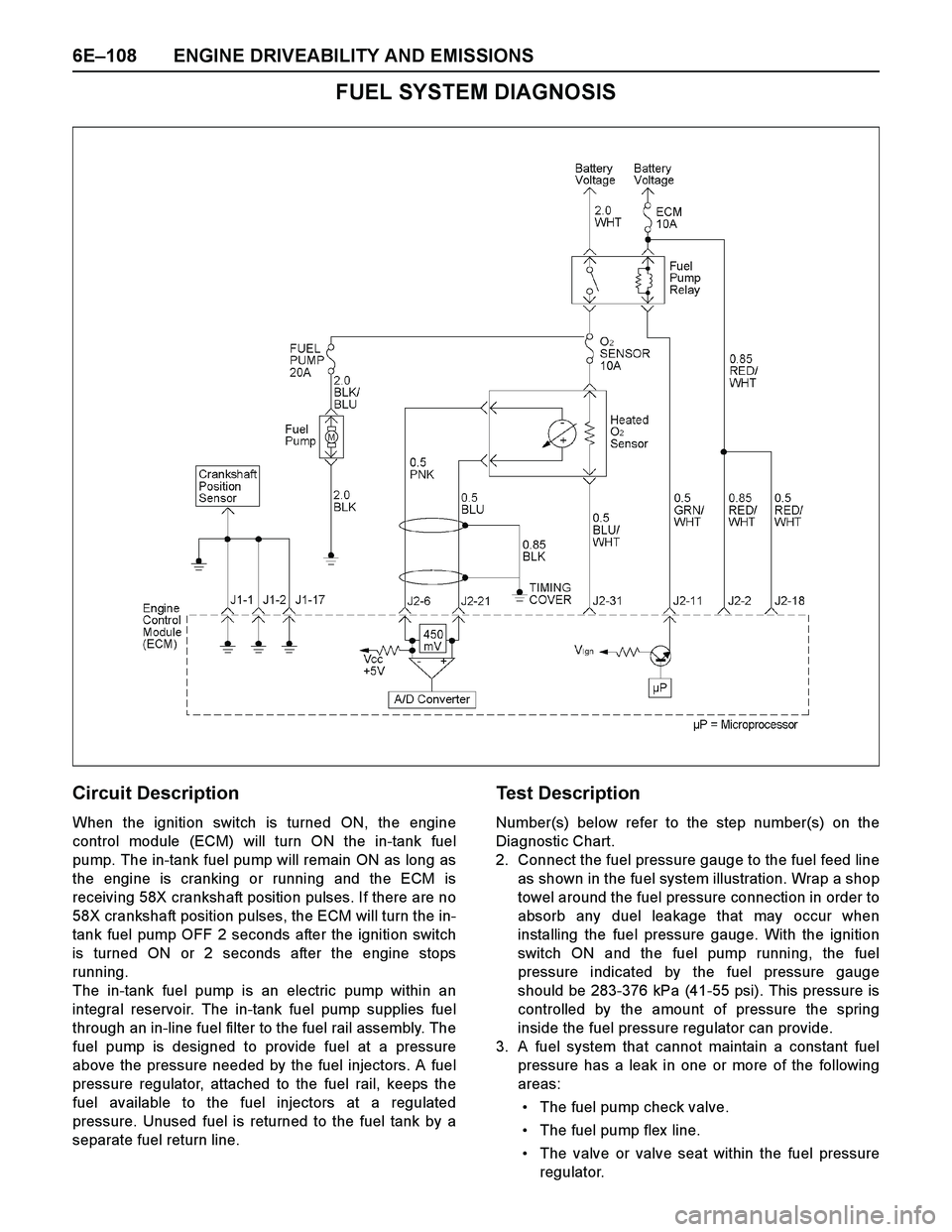
FUEL SYSTEM DIAGNOSIS
Circuit Description
When the ignition switch is turned ON, the engine
control module (ECM) will turn ON the in-tank fuel
pump. The in-tank fuel pump will remain ON as long as
the engine is cranking or running and the ECM is
receiving 58X crankshaft position pulses. If there are no
58X crankshaft position pulses, the ECM will turn the in-
tank fuel pump OFF 2 seconds after the ignition switch
is turned ON or 2 seconds after the engine stops
running.
The in-tank fuel pump is an electric pump within an
integral reservoir. The in-tank fuel pump supplies fuel
through an in-line fuel filter to the fuel rail assembly. The
fuel pump is designed to provide fuel at a pressure
above the pressure needed by the fuel injectors. A fuel
pressure regulator, attached to the fuel rail, keeps the
fuel available to the fuel injectors at a regulated
pressure. Unused fuel is returned to the fuel tank by a
separate fuel return line.
Test Description
Number(s) below refer to the step number(s) on the
Diagnostic Chart.
2. Connect the fuel pressure gauge to the fuel feed line
as shown in the fuel system illustration. Wrap a shop
towel around the fuel pressure connection in order to
absorb any duel leakage that may occur when
installing the fuel pressure gauge. With the ignition
switch ON and the fuel pump running, the fuel
pressure indicated by the fuel pressure gauge
should be 283-376 kPa (41-55 psi). This pressure is
controlled by the amount of pressure the spring
inside the fuel pressure regulator can provide.
3. A fuel system that cannot maintain a constant fuel
pressure has a leak in one or more of the following
areas:
The fuel pump check valve.
The fuel pump flex line.
The valve or valve seat within the fuel pressure
regulator.
Page 2690 of 4264
6E–114 ENGINE DRIVEABILITY AND EMISSIONS
Code Type DTC Name DTC Setting Condition Fail-Safe (Back Up) Recovery Condition Related Failure Parts Related
ECM
Pin No.
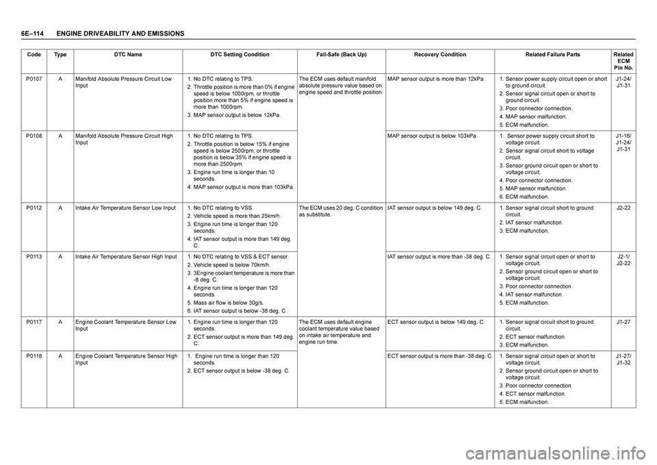
P0107 A Manifold Absolute Pressure Circuit Low
Input1. No DTC relating to TPS.
2. Throttle position is more than 0% if engine
speed is below 1000rpm, or throttle
position more than 5% if engine speed is
more than 1000rpm.
3. MAP sensor output is below 12kPa.The ECM uses default manifold
absolute pressure value based on
engine speed and throttle position.MAP sensor output is more than 12kPa. 1. Sensor power supply circuit open or short
to ground circuit.
2. Sensor signal circuit open or short to
ground circuit.
3. Poor connector connection.
4. MAP sensor malfunction.
5. ECM malfunction.J1-24/
J1-31
P0108 A Manifold Absolute Pressure Circuit High
Input1. No DTC relating to TPS.
2. Throttle position is below 15% if engine
speed is below 2500rpm, or throttle
position is below 35% if engine speed is
more than 2500rpm.
3. Engine run time is longer than 10
seconds.
4. MAP sensor output is more than 103kPa.MAP sensor output is below 103kPa. 1. Sensor power supply circuit short to
voltage circuit.
2. Sensor signal circuit short to voltage
circuit.
3. Sensor ground circuit open or short to
voltage circuit.
4. Poor connector connection.
5. MAP sensor malfunction.
6. ECM malfunction.J1-16/
J1-24/
J1-31
P0112 A Intake Air Temperature Sensor Low Input 1. No DTC relating to VSS.
2. Vehicle speed is more than 25km/h.
3. Engine run time is longer than 120
seconds.
4. IAT sensor output is more than 149 deg.
C. The ECM uses 20 deg. C condition
as substitute.IAT sensor output is below 149 deg. C. 1. Sensor signal circuit short to ground
circuit.
2. IAT sensor malfunction.
3. ECM malfunction.J2-22
P0113 A Intake Air Temperature Sensor High Input 1. No DTC relating to VSS & ECT sensor.
2. Vehicle speed is below 70km/h.
3. 3Engine coolant temperature is more than
-8 deg. C.
4. Engine run time is longer than 120
seconds.
5. Mass air flow is below 30g/s.
6. IAT sensor output is below -38 deg. C. IAT sensor output is more than -38 deg. C. 1. Sensor signal circuit open or short to
voltage circuit.
2. Sensor ground circuit open or short to
voltage circuit.
3. Poor connector connection
4. IAT sensor malfunction.
5. ECM malfunction.J2-1/
J2-22
P0117 A Engine Coolant Temperature Sensor Low
Input1. Engine run time is longer than 120
seconds.
2. ECT sensor output is more than 149 deg.
C. The ECM uses default engine
coolant temperature value based
on intake air temperature and
engine run time. ECT sensor output is below 149 deg. C. 1. Sensor signal circuit short to ground
circuit.
2. ECT sensor malfunction.
3. ECM malfunction.J1-27
P0118 A Engine Coolant Temperature Sensor High
Input1. Engine run time is longer than 120
seconds.
2. ECT sensor output is below -38 deg. C. ECT sensor output is more than -38 deg. C. 1. Sensor signal circuit open or short to
voltage circuit.
2. Sensor ground circuit open or short to
voltage circuit.
3. Poor connector connection
4. ECT sensor malfunction.
5. ECM malfunction.J1-27/
J1-32
Page 2695 of 4264
ENGINE DRIVEABILITY AND EMISSIONS 6E–119
DIAGNOSTIC TROUBLE CODE (DTC) P0107 MANIFOLD ABSOLUTE
PRESSURE CIRCUIT LOW INPUT
Condition for setting the DTC and action taken when the DTC sets
Circuit Description
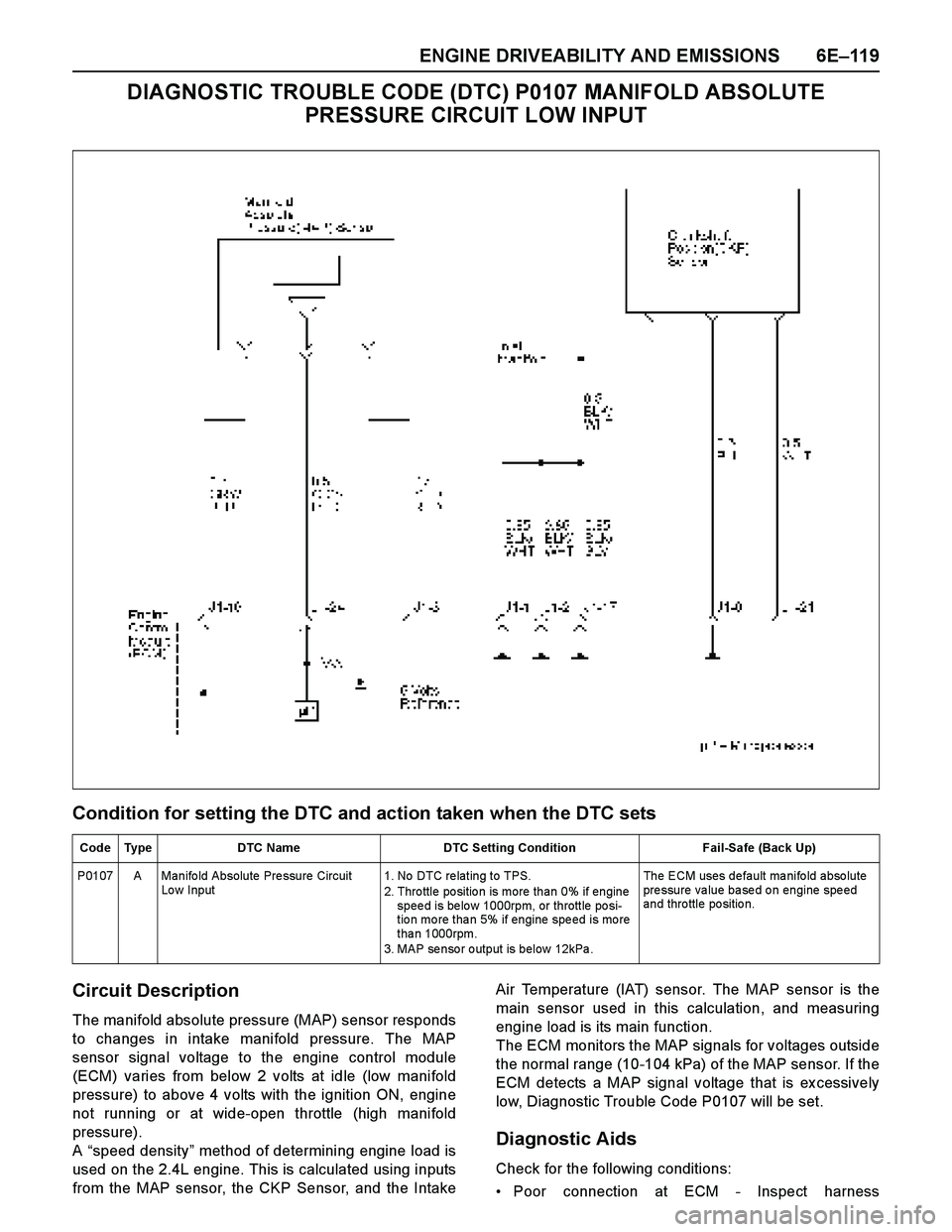
The manifold absolute pressure (MAP) sensor responds
to changes in intake manifold pressure. The MAP
sensor signal voltage to the engine control module
(ECM) varies from below 2 volts at idle (low manifold
pressure) to above 4 volts with the ignition ON, engine
not running or at wide-open throttle (high manifold
pressure).
A “speed density” method of determining engine load is
used on the 2.4L engine. This is calculated using inputs
from the MAP sensor, the CKP Sensor, and the IntakeAir Temperature (IAT) sensor. The MAP sensor is the
main sensor used in this calculation, and measuring
engine load is its main function.
The ECM monitors the MAP signals for voltages outside
the normal range (10-104 kPa) of the MAP sensor. If the
ECM detects a MAP signal voltage that is ex cessively
low, Diagnostic Trouble Code P0107 will be set.
Diagnostic Aids
Check for the following conditions:
Poor connection at ECM - Inspect harness
Code Type DTC Name DTC Setting Condition Fail-Safe (Back Up)
P0107 A Manifo ld Absolute Pre ssure Circuit
Lo w Input1. No DTC re lating to TPS.
2. Throttle position is more than 0% if engine
spee d is be lo w 1000rpm, or throttle po si-
tio n mo re tha n 5% if engine spe ed is mo re
than 1000rpm.
3. MAP se nso r o utput is below 12kPa .The ECM uses default manifold absolute
pressure value based on engine speed
and thro ttle po sitio n.
Page 2696 of 4264

6E–120 ENGINE DRIVEABILITY AND EMISSIONS
connectors for backed-out terminals, improper
mating, broken locks, improperly formed or damaged
terminals, and poor terminal-to-wire connection.
If these codes are also set, it could indicate a
problem with the 5 Volt reference circuit.
Damaged harness - Inspect the wiring harness fordamage, short to ground, short to battery positive,
and open circuit. If the harness appears to be OK,
observe the MAP display on the Tech 2 while moving
connectors and wiring harnesses related to the
sensor. A change in the display will indicate the
location of the fault.
Diagnostic Trouble Code (DTC) P0107
Manifold Absolute Pressure Circuit Low Input
Step A ction Value(s) Yes No
1 Was the “On-Board Diagnostic (OBD) System Check”
performed?
—Go to Step 2Go to On Board
Diagnostic
(OBD) System
Check
2 1. Connect the Tech 2.
2. Review and record the failure information.
3. Select “F0: Read DTC Infor By Priority” in “F0:
Diagnostic Trouble Code”.
Is the DTC P0107 stored as “Present Failure”?—Go to Step 3Refer to
Diagnostic Aids
and Go to Step
3
3 1. Using the Tech2, ignition “On” and engine “Off”.
2. Select “Clear DTC Information” with the Tech2 and
clear the DTC information.
3. Operate the vehicle and monitor the “F5: Failed
This Ignition” in “F2: DTC Information”.
Was the DTC P0107 stored in this ignition cycle?—Go to Step 4Refer to
Diagnostic Aids
and Go to Step
4
4 Check for poor/faulty connection at the MAP sensor or
ECM connector. If a poor/faulty connection is found,
repair as necessary.
Was the problem found?
—Verify repair Go to Step 5
5 Visually check the MAP.
Was the problem found? —Go to Step 9 Go to Step 6
6 Using the DVM and check the MAP sensor power
supply circuit.
1. Ignition “On”, engine “Off”.
2. Disconnect the MAP sensor connector.
3. Check the circuit for open or short to ground
circuit.
Was the DVM indicated specified value?
Approx imately
5.0V Go to Step 8Go to Step 7
16
31 24E85 E60(J1)
V
E85
3
Page 2699 of 4264
ENGINE DRIVEABILITY AND EMISSIONS 6E–123
DIAGNOSTIC TROUBLE CODE (DTC) P0108 MANIFOLD ABSOLUTE
PRESSURE CIRCUIT HIGH INPUT
Condition for setting the DTC and action taken when the DTC sets
Circuit Description
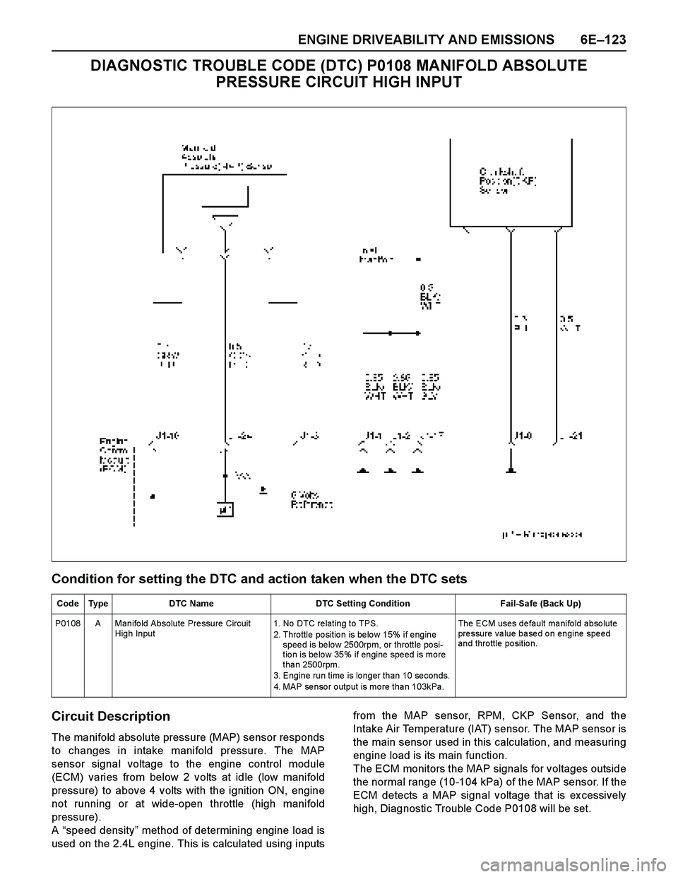
The manifold absolute pressure (MAP) sensor responds
to changes in intake manifold pressure. The MAP
sensor signal voltage to the engine control module
(ECM) varies from below 2 volts at idle (low manifold
pressure) to above 4 volts with the ignition ON, engine
not running or at wide-open throttle (high manifold
pressure).
A “speed density” method of determining engine load is
used on the 2.4L engine. This is calculated using inputsfrom the MAP sensor, RPM, CKP Sensor, and the
Intake Air Temperature (IAT) sensor. The MAP sensor is
the main sensor used in this calculation, and measuring
engine load is its main function.
The ECM monitors the MAP signals for voltages outside
the normal range (10-104 kPa) of the MAP sensor. If the
ECM detects a MAP signal voltage that is ex cessively
high, Diagnostic Trouble Code P0108 will be set.
Code Type DTC Name DTC Setting Condition Fail-Safe (Back Up)
P0108 A Manifo ld Absolute Pre ssure Circuit
High Input1. No DTC re lating to TPS.
2. Thro ttle po sitio n is be lo w 15% if e ngine
spee d is be lo w 2500rpm, or throttle po si-
tio n is be lo w 35% if engine spe ed is mo re
than 2500rpm.
3. Engine run time is longer than 10 seconds.
4. MAP se nso r o utput is mo re tha n 103kPa.The ECM uses default manifold absolute
pressure value based on engine speed
and thro ttle po sitio n.
Page 2700 of 4264
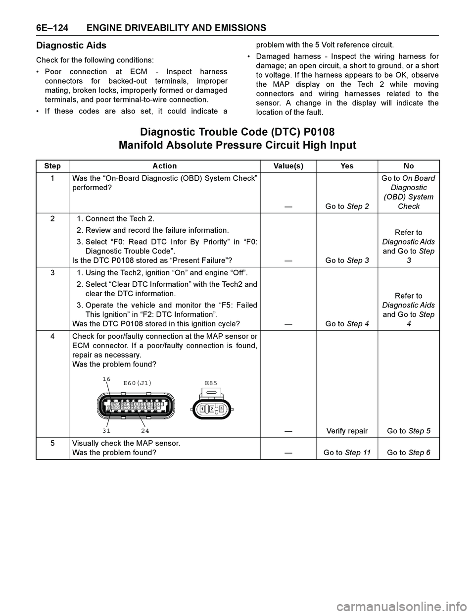
6E–124 ENGINE DRIVEABILITY AND EMISSIONS
Diagnostic Aids
Check for the following conditions:
Poor connection at ECM - Inspect harness
connectors for backed-out terminals, improper
mating, broken locks, improperly formed or damaged
terminals, and poor terminal-to-wire connection.
If these codes are also set, it could indicate aproblem with the 5 Volt reference circuit.
Damaged harness - Inspect the wiring harness for
damage; an open circuit, a short to ground, or a short
to voltage. If the harness appears to be OK, observe
the MAP display on the Tech 2 while moving
connectors and wiring harnesses related to the
sensor. A change in the display will indicate the
location of the fault.
Diagnostic Trouble Code (DTC) P0108
Manifold Absolute Pressure Circuit High Input
Step Action Value(s) Yes No
1Was the “On-Board Diagnostic (OBD) System Check”
performed?
—Go to Step 2Go to On Board
Diagnostic
(OBD) System
Check
2 1. Connect the Tech 2.
2. Review and record the failure information.
3. Select “F0: Read DTC Infor By Priority” in “F0:
Diagnostic Trouble Code”.
Is the DTC P0108 stored as “Present Failure”?—Go to Step 3Refer to
Diagnostic Aids
and Go to Step
3
3 1. Using the Tech2, ignition “On” and engine “Off”.
2. Select “Clear DTC Information” with the Tech2 and
clear the DTC information.
3. Operate the vehicle and monitor the “F5: Failed
This Ignition” in “F2: DTC Information”.
Was the DTC P0108 stored in this ignition cycle?—Go to Step 4Refer to
Diagnostic Aids
and Go to Step
4
4 Check for poor/faulty connection at the MAP sensor or
ECM connector. If a poor/faulty connection is found,
repair as necessary.
Was the problem found?
—Verify repair Go to Step 5
5 Visually check the MAP sensor.
Was the problem found?—Go to Step 11Go to Step 6
16
31 24E85 E60(J1)
Page 2730 of 4264
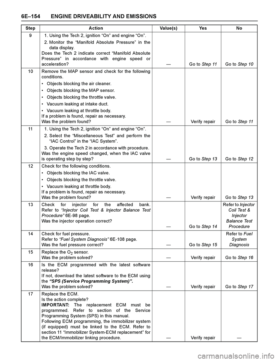
6E–154 ENGINE DRIVEABILITY AND EMISSIONS
9 1. Using the Tech 2, ignition “On” and engine “On”.
2. Monitor the “Manifold Absolute Pressure” in the
data display.
Does the Tech 2 indicate correct “Manifold Absolute
Pressure” in accordance with engine speed or
acceleration? —Go to Step 11Go to Step 10
10 Remove the MAP sensor and check for the following
conditions.
Objects blocking the air cleaner.
Objects blocking the MAP sensor.
Objects blocking the throttle valve.
Vacuum leaking at intake duct.
Vacuum leaking at throttle body.
If a problem is found, repair as necessary.
Was the problem found?—Verify repair Go to Step 11
11 1. Using the Tech 2, ignition “On” and engine “On”.
2. Select the “Miscellaneous Test” and perform the
“IAC Control” in the “IAC System”.
3. Operate the Tech 2 in accordance with procedure.
Was the engine speed changed, when the IAC valve
is operating step by step?—Go to Step 13Go to Step 12
12 Check for the following conditions.
Objects blocking the IAC valve.
Objects blocking the throttle valve.
Vacuum leaking at throttle body.
If a problem is found, repair as necessary.
Was the problem found?—Verify repair Go to Step 13
13 Check for injector for the affected bank.
Refer to “Injector Coil Test & Injector Balance Test
Procedure” 6E-98 page.
Was the injector operation correct?
—Go to Step 14Refer to Injector
Coil Test &
Injector
Balance Test
Procedure
14 Check for fuel pressure.
Refer to “Fuel System Diagnosis” 6E-108 page.
Was the fuel pressure correct? —Go to Step 15Refer to Fuel
System
Diagnosis
15 Replace the O
2 sensor.
Was the problem solved?—Verify repair Go to Step 16
16 Is the ECM programmed with the latest software
release?
If not, download the latest software to the ECM using
the “SPS (Service Programming System)”.
Was the problem solved?—Verify repair Go to Step 17
17 Replace the ECM.
Is the action complete?
IMPORTANT: The replacement ECM must be
programmed. Refer to section of the Service
Programming System (SPS) in this manual.
Following ECM programming, the immobilizer system
(if equipped) must be linked to the ECM. Refer to
section 11 “Immobilizer System-ECM replacement” for
the ECM/Immobilizer linking procedure.—Veri fy repai r— Step A ction Value(s) Yes No
Page 2733 of 4264
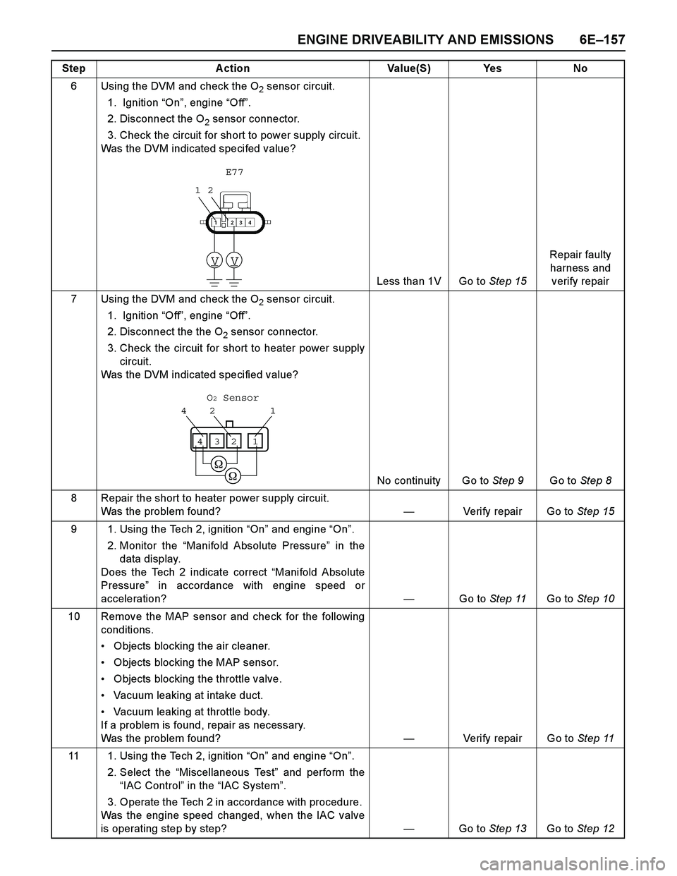
ENGINE DRIVEABILITY AND EMISSIONS 6E–157
6 Using the DVM and check the O2 sensor circuit.
1. Ignition “On”, engine “Off”.
2. Disconnect the O
2 sensor connector.
3. Check the circuit for short to power supply circuit.
Was the DVM indicated specifed value?
Less than 1V Go to Step 15Repair faulty
harness and
verify repair
7 Using the DVM and check the O
2 sensor circuit.
1. Ignition “Off”, engine “Off”.
2. Disconnect the the O
2 sensor connector.
3. Check the circuit for short to heater power supply
circuit.
Was the DVM indicated specified value?
No continuity Go to Step 9Go to Step 8
8 Repair the short to heater power supply circuit.
Was the problem found?—Verify repair Go to Step 15
9 1. Using the Tech 2, ignition “On” and engine “On”.
2. Monitor the “Manifold Absolute Pressure” in the
data display.
Does the Tech 2 indicate correct “Manifold Absolute
Pressure” in accordance with engine speed or
acceleration? —Go to Step 11Go to Step 10
10 Remove the MAP sensor and check for the following
conditions.
Objects blocking the air cleaner.
Objects blocking the MAP sensor.
Objects blocking the throttle valve.
Vacuum leaking at intake duct.
Vacuum leaking at throttle body.
If a problem is found, repair as necessary.
Was the problem found?—Verify repair Go to Step 11
11 1. Using the Tech 2, ignition “On” and engine “On”.
2. Select the “Miscellaneous Test” and perform the
“IAC Control” in the “IAC System”.
3. Operate the Tech 2 in accordance with procedure.
Was the engine speed changed, when the IAC valve
is operating step by step?—Go to Step 13Go to Step 12 Step A ction Value(S) Yes No
12
VV
E77
1 2 4
1234
O2 Sensor