Page 980 of 4264
8A-322 ELECTRICAL-BODY AND CHASSIS
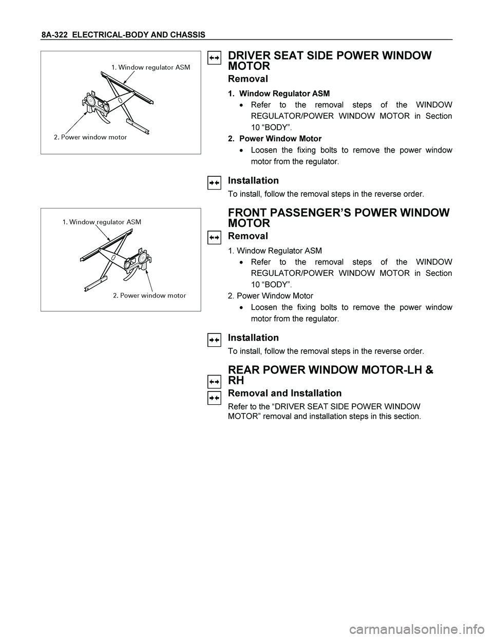
DRIVER SEAT SIDE POWER WINDOW
MOTOR
Removal
1. Window Regulator ASM
� Refer to the removal steps of the WINDOW
REGULATOR/POWER WINDOW MOTOR in Section
10 “BODY”.
2. Power Window Motor
� Loosen the fixing bolts to remove the power windo
w
motor from the regulator.
Installation
To install, follow the removal steps in the reverse order.
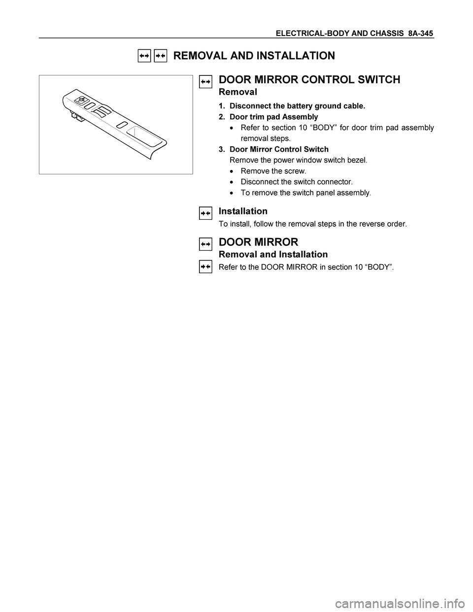
FRONT PASSENGER’S POWER WINDOW
MOTOR
Removal
1. Window Regulator ASM
� Refer to the removal steps of the WINDOW
REGULATOR/POWER WINDOW MOTOR in Section
10 “BODY”.
2. Power Window Motor
� Loosen the fixing bolts to remove the power windo
w
motor from the regulator.
Installation
To install, follow the removal steps in the reverse order.
REAR POWER WINDOW MOTOR-LH &
RH
Removal and Installation
Refer to the “DRIVER SEAT SIDE POWER WINDOW
MOTOR” removal and installation steps in this section.
Page 994 of 4264
8A-336 ELECTRICAL-BODY AND CHASSIS
REMOVAL AND INSTALLATION
AUDIO
Refer to Section 9 “ACCESSORIES” for details.
CIGARETTE LIGHTER
Removal
1. Disconnect the battery ground cable.
2. Remove the center cluster ASM.
3. Remove the lighter
1.
4. Disconnect the connector
2.
5. Loosen the ring nut
3 at the back side.
6. Remove the outer case
4.
7. Remove the lighter holder
5 from the bezel.
Installation
Follow the removal procedure in the reverse order to install the
lighter.
Pay close attention to the important points mentioned in the
following paragraphs.
Connector
Be absolutely sure that the lighter connector is securely
connected.
This will prevent a poor contact and an open circuit.
ACC SOCKET
Removal
1. Disconnect the battery ground cable.
2. Remove the center cluster ASM.
3. Disconnect the connector.
4. Remove the holder nut
1.
5. Remove the ACC Socket
2
Installation
Follow the removal procedure in the reverse order to install the
lighter.
Page 1003 of 4264
ELECTRICAL-BODY AND CHASSIS 8A-345
REMOVAL AND INSTALLATION
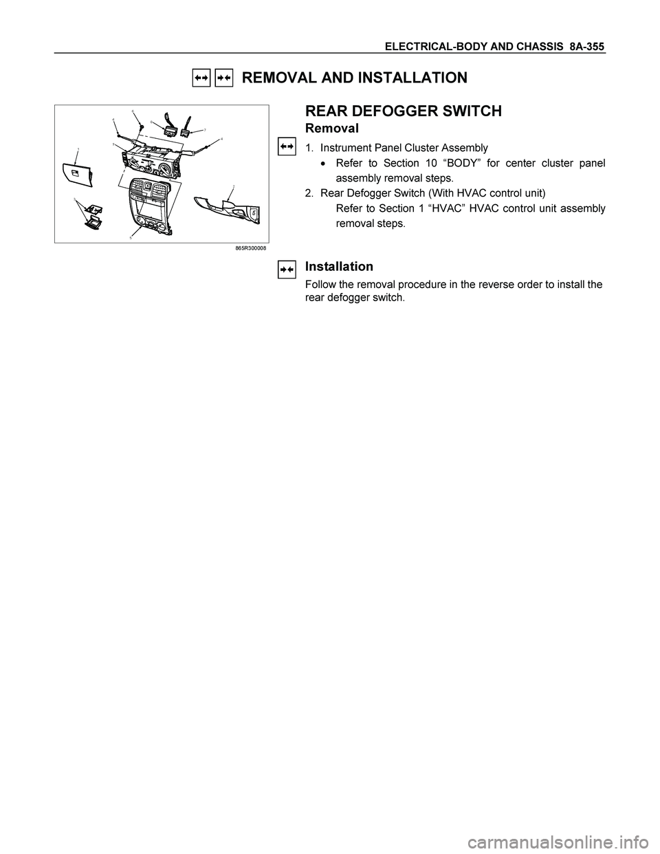
DOOR MIRROR CONTROL SWITCH
Removal
1. Disconnect the battery ground cable.
2. Door trim pad Assembly
� Refer to section 10 “BODY” for door trim pad assembly
removal steps.
3. Door Mirror Control Switch
Remove the power window switch bezel.
� Remove the screw.
� Disconnect the switch connector.
� To remove the switch panel assembly.
Installation
To install, follow the removal steps in the reverse order.
DOOR MIRROR
Removal and Installation
Refer to the DOOR MIRROR in section 10 “BODY”.
Page 1013 of 4264
ELECTRICAL-BODY AND CHASSIS 8A-355
REMOVAL AND INSTALLATION
865R300008
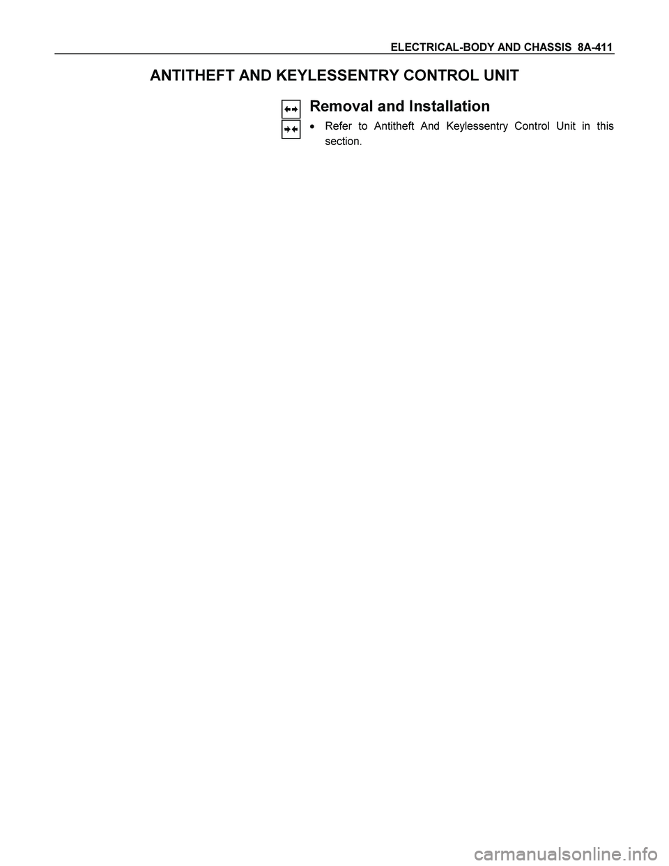
REAR DEFOGGER SWITCH
Removal
1. Instrument Panel Cluster Assembly
� Refer to Section 10 “BODY” for center cluster panel
assembly removal steps.
2. Rear Defogger Switch (With HVAC control unit)
Refer to Section 1 “HVAC” HVAC control unit assembly
removal steps.
Installation
Follow the removal procedure in the reverse order to install the
rear defogger switch.
Page 1069 of 4264
ELECTRICAL-BODY AND CHASSIS 8A-411
ANTITHEFT AND KEYLESSENTRY CONTROL UNIT
Removal and Installation
� Refer to Antitheft And Keylessentry Control Unit in this
section.
Page 1099 of 4264

CRUISE CONTROL SYSTEM 8B-1
SECTION 8B
CRUISE CONTROL SYSTEM
TABLE OF CONTENTS
PAGE
Service Precaution .........................................................................................................................8B- 3
General Description .......................................................................................................................8B- 3
Brake Switch ...................................................................................................................................8B- 5
Removal .......................................................................................................................................8B- 5
Installation ..................................................................................................................................8B- 5
Adjustment ..................................................................................................................................8B- 6
Clutch switch ...................................................................................................................................8B- 6
Removal and Installation ........................................................................................................8B- 6
Adjustment ..................................................................................................................................8B- 6
Starter Switch ..................................................................................................................................8B- 6
Removal .......................................................................................................................................8B- 6
Installation ..................................................................................................................................8B- 6
Cruise Control Main Switch .........................................................................................................8B- 7
Removal .......................................................................................................................................8B- 7
Installation ..................................................................................................................................8B- 7
Cruise Control Switch (Combination Switch) ........................................................................8B- 7
Removal and Installation ........................................................................................................8B- 7
Cruise Control Unit ........................................................................................................................8B- 8
Removal .......................................................................................................................................8B- 8
Installation ..................................................................................................................................8B- 8
Cruise Actuator ...............................................................................................................................8B- 8
Actuator Cable Diagram ..........................................................................................................8B- 9
Removal .......................................................................................................................................8B- 9
Installation ..................................................................................................................................8B- 9
Adjustment ..................................................................................................................................8B- 9
Mode Switch ....................................................................................................................................8B- 9
Removal and Installation ........................................................................................................8B- 9
Page 1104 of 4264

8B-6 CRUISE CONTROL SYSTEM
Adjustment
1. Check to be sure that the brake pedal has been completely
returned by the return spring.
2. Disconnect the switch connector.
RTW3A0SH001201
3. Release the lock (2) by turning the switch (1) counter-clock-
wise.
4. After doing so, pull the pedal arm (3) to you a little so tha
t
the pedal arm is not pushed in.
5. Making the pedal arm not movable with one hand, push in
the whole switch with the other hand until the plunger of the
switch is pushed in and the switch itself hits the rubber o
f
the pedal arm.
In the condition, turn the switch clock-wise until "click"
sound is made and lock it.
By doing this, the switch is adjusted at 0.2 to 1.2mm (0.01-
0.06 in.) clearance.
Clutch Switch
Removal and Installation
Refer to the Clutch Control removal and installation steps in
Clutch section.
Adjustment
1. Turn the clutch switch or stopper bolt 1 until the switch bolt
or stopper bolt just touches the clutch pedal arm.
2. Adjust clutch switch or stopper bolt by backing it out half a
turn, and measure the clearance (L) between the clutch
pedal arm and the clutch switch bolt end or stopper bolt.
3. Lock the lock nut
2.
4. Connect the clutch switch connector.
Clutch switch and clutch and clutch pedal clearance
mm (in)
Limit 0.5-1.5 (0.020-0.059)
Starter Switch
431R300001
Removal
1. Steering Lock Assembly
� Refer to the Steering Lock assembly removal steps o
f
"Steering Column" in Power-Assisted Steering System
section.
2. Starter Switch
Installation
Follow the removal procedure in the reverse order to install the
starter switch.
Page 1105 of 4264
CRUISE CONTROL SYSTEM 8B-7
Cruise Control Main Switch
Removal
1. Disconnect the battery ground cable.
RTW3A0SH001301
2. Remove the side ventilation grille.
RTW3A0SH001401
3. Disconnect the switch connector and push the lock from the
backside of the side ventilation grille to remove the cruise
control main switch.
Installation
To install, follow the removal steps in the reverse order, noting
the following point.
1. Push in the switch with your fingers until it locks securely.
Cruise Control Switch (Combination Switch)
Removal and Installation
Refer to the Lighting Switch (Combination Switch) removal and
installation steps of Lighting System in Body and Accessories
section.