Page 4083 of 4264
DIAGNOSIS (JR405E) 7A2-91
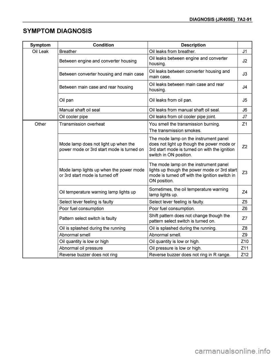
SYMPTOM DIAGNOSIS
Symptom Condition Description
Oil Leak Breather Oil leaks from breather. J1
Between engine and converter housing Oil leaks between engine and converter
housing. J2
Between converter housing and main caseOil leaks between converter housing and
main case. J3
Between main case and rear housing Oil leaks between main case and rear
housing. J4
Oil pan Oil leaks from oil pan. J5
Manual shaft oil seal Oil leaks from manual shaft oil seal. J6
Oil cooler pipe Oil leaks from oil cooler pipe joint. J7
Other Transmission overheat You smell the transmission burning. Z1
� The transmission smokes.
Mode lamp does not light up when the
power mode or 3rd start mode is turned on
The mode lamp on the instrument panel
does not light up though the power mode or
3rd start mode is turned on with the ignition
switch in ON position.
Z2
Mode lamp lights up when the power mode
or 3rd start mode is turned off
The mode lamp on the instrument panel
lights up though the power mode or 3rd start
mode is turned off with the ignition switch in
ON position.
Z3
Oil temperature warning lamp lights up Sometimes, the oil temperature warning
lamp lights up. Z4
Select lever feeling is faulty Select lever feeling is faulty. Z5
Poor fuel consumption Poor fuel consumption. Z6
Pattern select switch is faulty Shift pattern does not change though the
pattern select switch is turned on. Z7
Oil is splashed during the running Oil is splashed during the running. Z8
Abnormal smell Abnormal smell. Z9
Oil quantity is low or high Oil quantity is low or high. Z10
Abnormal oil pressure Oil pressure is low or high. Z11
Reverse buzzer does not ring Reverse buzzer does not ring in R range. Z12
Page 4116 of 4264
7A2-124 DIAGNOSIS (JR405E)
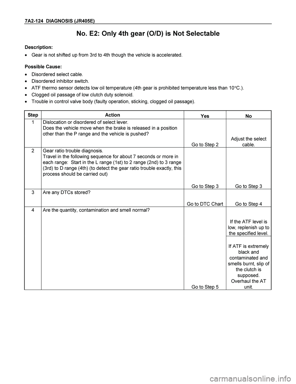
No. E2: Only 4th gear (O/D) is Not Selectable
Description:
� Gear is not shifted up from 3rd to 4th though the vehicle is accelerated.
Possible Cause:
� Disordered select cable.
� Disordered inhibitor switch.
� ATF thermo sensor detects low oil temperature (4th gear is prohibited temperature less than 10�C.).
� Clogged oil passage of low clutch duty solenoid.
� Trouble in control valve body (faulty operation, sticking, clogged oil passage).
Step Action Yes No
1 Dislocation or disordered of select lever.
Does the vehicle move when the brake is released in a position
other than the P range and the vehicle is pushed?
Go to Step 2
Adjust the select
cable.
2 Gear ratio trouble diagnosis.
Travel in the following sequence for about 7 seconds or more in
each range: Start in the L range (1st) to 2 range (2nd) to 3 range
(3rd) to D range (4th) (to detect the gear ratio trouble exactly, this
process should be carried out)
Go to Step 3 Go to Step 3
3 Are any DTCs stored?
Go to DTC Chart Go to Step 4
4 Are the quantity, contamination and smell normal?
If the ATF level is
low, replenish up to
the specified level.
Go to Step 5
If ATF is extremely
black and
contaminated and
smells burnt, slip of
the clutch is
supposed.
Overhaul the AT
unit.
Page 4117 of 4264
DIAGNOSIS (JR405E) 7A2-125
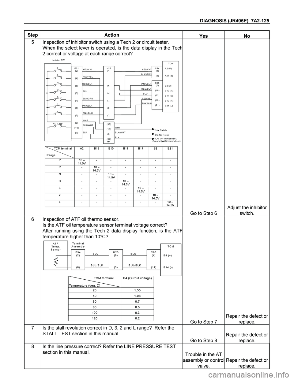
Step Action Yes No
5 Inspection of inhibitor switch using a Tech 2 or circuit tester.
When the select lever is operated, is the data display in the Tech
2 correct or voltage at each range correct?
Inhibitor SW
TCM
A2 (P)
A17 (3)
B2 (2)
B10 (N)
B11 (D)
B19 (R)
B21 (L)
C95
(2 )
(10)
(11 )
(19)
(21) Y E L /V IO
RED/BLK
BLUBLK/GRN
Starter Relay
C94
(2 )
(3 )
BH22
(1)
(6)
(4)
(7)
(5)
(2) P
2
R
N
D
3
L
Start SW
PNK/BLU
E51
(2)
(4)
(8)
(5)
(1)
(9)
(6)
(3)
(10)
(7)
(38)
(15)
(3)
(37)
H4PNK/BLK
RED/YEL Y E L /V IO
BLK/GRN
PNK/BLK RED/BLK
BLU RED/YEL
PNK/BLU
BLK/WHT
BLK
BLK BLK/WHT Key Switch WHT
WHT
ICU (W/ Immobilis e r)
Ground (W/O Immobilis e r)
TCM terminal
RangeA2 B19 B10 B11 B17 B2 B21
P10 –
14.5V-- - - - -
R-10 –
14.5V-- ---
N--10 –
14.5V----
D - - - 10 –
14.5V---
3----10 –
14.5V--
2-----10 –
14.5V-
L------10 –
14.5V
Go to Step 6
Adjust the inhibitor
switch.
6 Inspection of ATF oil thermo sensor.
Is the ATF oil temperature sensor terminal voltage correct?
After running using the Tech 2 data display function, is the ATF
temperature higher than 10�C?
ATF
Te m p .
SensorTCM
B4 (+)
B14 (-)
H23
(8 )
(3 )C95
(4)
(14) BLU Te rm i n a l
Assembly
BLU/BLKE54
(2 )
(8 ) BLU
BLU/BLK
TCM terminal
Temperature (deg. C)
B4 (Output voltage)
201.55
401.08
600.7
800.5
1000.3
1200.2Go to Step 7
Repair the defect or
replace.
7 Is the stall revolution correct in D, 3, 2 and L range? Refer the
STALL TEST section in this manual.
Go to Step 8
Repair the defect or
replace.
8 Is the line pressure correct? Refer the LINE PRESSURE TEST
section in this manual. Trouble in the AT
assembly or control
valve.
Repair the defect or
replace.
Page 4126 of 4264
7A2-134 DIAGNOSIS (JR405E)
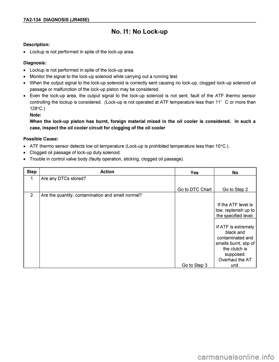
No. I1: No Lock-up
Description:
� Lockup is not performed in spite of the lock-up area.
Diagnosis:
� Lockup is not performed in spite of the lock-up area.
� Monitor the signal to the lock-up solenoid while carrying out a running test.
� When the output signal to the lock-up solenoid is correctly sent causing no lock-up, clogged lock-up solenoid oil
passage or malfunction of the lock-up piston may be considered.
� Even the lock-up area, the output signal to the lock-up solenoid is not sent, fault of the ATF thermo sensor
controlling the lockup is considered. (Lock-up is not operated at ATF temperature less than 11�C or more than
128�C.)
Note:
When the lock-up piston has burnt, foreign material mixed in the oil cooler is considered. In such a
case, inspect the oil cooler circuit for clogging of the oil cooler
Possible Cause:
� ATF thermo sensor detects low oil temperature (Lock-up is prohibited temperature less than 10�C.).
� Clogged oil passage of lock-up duty solenoid.
� Trouble in control valve body (faulty operation, sticking, clogged oil passage).
Step Action Yes No
1 Are any DTCs stored?
Go to DTC Chart Go to Step 2
2 Are the quantity, contamination and smell normal?
If the ATF level is
low, replenish up to
the specified level.
Go to Step 3
If ATF is extremely
black and
contaminated and
smells burnt, slip of
the clutch is
supposed.
Overhaul the AT
unit.
Page 4127 of 4264
DIAGNOSIS (JR405E) 7A2-135
Step Action Yes No
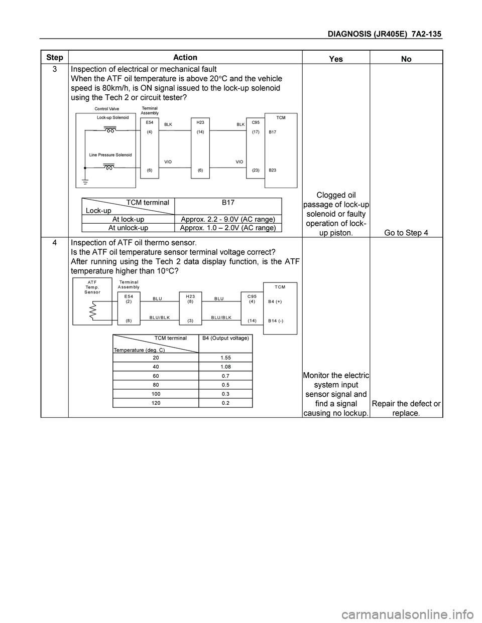
3 Inspection of electrical or mechanical fault
When the ATF oil temperature is above 20�C and the vehicle
speed is 80km/h, is ON signal issued to the lock-up solenoid
using the Tech 2 or circuit tester?
Control Valve
TCM
B17
B23 BLK Lock-up Solenoid
Terminal
Assembly
VIO Line Pressure Solenoid
E54
(4)
(6)H23
(14)
(6)C95
(17)
(23) BLK
VIO
TCM terminal
Lock-upB17
At lock-up Approx. 2.2 - 9.0V (AC range)
At unlock-up Approx. 1.0 – 2.0V (AC range)
Clogged oil
passage of lock-up
solenoid or faulty
operation of lock-
up piston. Go to Step 4
4 Inspection of ATF oil thermo sensor.
Is the ATF oil temperature sensor terminal voltage correct?
After running using the Tech 2 data display function, is the ATF
temperature higher than 10�C?
AT F
Te m p .
SensorTCM
B4 (+)
B14 (-)
H23
(8)
(3)C95
(4)
(1 4) BLU Te r m in a l
Assembly
BLU/BLKE54
(2)
(8) BLU
BLU/BLK
TCM terminal
Temperature (deg. C)
B4 (Output voltage)
201.55
401.08
600.7
800.5
1000.3
1200.2
Monitor the electric
system input
sensor signal and
find a signal
causing no lockup.
Repair the defect or
replace.
Page 4129 of 4264
DIAGNOSIS (JR405E) 7A2-137
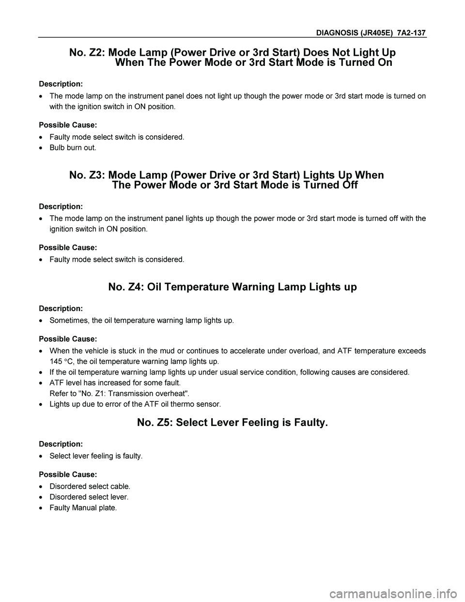
No. Z2: Mode Lamp (Power Drive or 3rd Start) Does Not Light Up
When The Power Mode or 3rd Start Mode is Turned On
Description:
� The mode lamp on the instrument panel does not light up though the power mode or 3rd start mode is turned on
with the ignition switch in ON position.
Possible Cause:
� Faulty mode select switch is considered.
� Bulb burn out.
No. Z3: Mode Lamp (Power Drive or 3rd Start) Lights Up When
The Power Mode or 3rd Start Mode is Turned Off
Description:
� The mode lamp on the instrument panel lights up though the power mode or 3rd start mode is turned off with the
ignition switch in ON position.
Possible Cause:
� Faulty mode select switch is considered.
No. Z4: Oil Temperature Warning Lamp Lights up
Description:
� Sometimes, the oil temperature warning lamp lights up.
Possible Cause:
� When the vehicle is stuck in the mud or continues to accelerate under overload, and ATF temperature exceeds
145 �C, the oil temperature warning lamp lights up.
� If the oil temperature warning lamp lights up under usual service condition, following causes are considered.
� ATF level has increased for some fault.
Refer to "No. Z1: Transmission overheat".
� Lights up due to error of the ATF oil thermo sensor.
No. Z5: Select Lever Feeling is Faulty.
Description:
� Select lever feeling is faulty.
Possible Cause:
� Disordered select cable.
� Disordered select lever.
� Faulty Manual plate.
Page 4130 of 4264
7A2-138 DIAGNOSIS (JR405E)
No. Z6: Poor Fuel Consumption
Description:
� Poor fuel consumption.
Diagnosis Hints:
� Basically same causes as "No. C1 - C8: Engine races up (slip) by shift up or shift down" are considered.
No. Z7: Pattern Select Switch is Faulty
Description:
� Shift pattern does not change though the pattern select switch is turned on.
Possible Cause:
� Faulty mode select switch is considered.
No. Z8: Oil is Splashed During the Running
Description:
� Oil is splashed during the running
Possible Cause:
� ATF quantity is too high.
No. Z9: Abnormal Smell
Description:
� Abnormal smell.
Diagnosis Hints:
� Basically a trouble in the AT main unit.
No. Z10: ATF Quantity is Low or High
Description:
� Oil quantity is low or high.
Possible Cause:
� In case of oil level is high.
ATF temperature is low when ATF quantity is checked.
� In case of oil level is low.
ATF leaks is considered. Check the AT main unit and cooler circuit.
Page 4134 of 4264
7A2-142 DIAGNOSIS (JR405E)
1. Oil Cooler Out
2. R Range Line Pressure Detection Port
(Low & Reverse Brake Pressure Detection Port)
3. D, 3, 2 & L Range Line Pressure Detection Port
(Low Clutch Pressure Detection Port)
4. Oil Cooler In
4. If the line pressure is lower than standard value at
idling in L and R ranges.
�
ATF leaking from low and reverse brake hydraulic
circuit.
5. If the line pressure is higher than standard value at
idling in all ranges.
� Throttle opening signal reception error.
� Faulty oil temperature sensor.
� Faulty operation of low clutch solenoid.
� Sticking pilot valve.
� Sticking pressure regulator valve or plug.
6. If the line pressure is lower than standard value at stall
speed in all ranges.
� Throttle opening signal reception error.
� Faulty operation of line pressure solenoid.
� Faulty operation of low clutch solenoid.
� Sticking pilot valve.
� Sticking pressure regulator valve or plug.