Page 3478 of 4264
3B-48 POWER-ASSISTED STEERING SYSTEM
13. Align the each snap stud of driver air bag to the hole
of steering wheel. (with SRS air bag)
060R300030
060R300020
14. Push the SRS air bag area1 and area2. At that time
confirm the audible noise of each stud. (with SRS ai
r
bag)
060R300036
15. Enable the SRS (Refer to "Enabling the SRS" in this
section). (with SRS air bag)
16. Install driver knee bolster (reinforcement).
17. Install instrument panel lower cover then Install the
engine hood opening lever.
18. Connect the SRS connector. (with SRS air bag)
19. Connect the battery "-" terminal cable. (with SRS ai
r
bag)
20. Turn the ignition switch to "ON" while watching
warning light and check the light should flash 7 times
and then go off. If lamp does not operate correctly,
refer to Restraints section.
Page 3480 of 4264
3B-50 POWER-ASSISTED STEERING SYSTEM
CAUTION: The wheels of the vehicle must be
straight ahead and the steering column in the
"LOCK" position before disconnecting the steering
wheel. Failure to do so will cause the coil assembly
to become uncentered which will cause damage to
the coil assembly. (with SRS air bag)
5. Remove the engine hood opening lever and
steering lower cover.
6. Remove driver knee bolster (reinforcement).
7. Disable the SRS (Refer to "Disabling the SRS" in
this section). (with SRS air bag)
8. Check the both side hole of the steering cover. (with
SRS air bag)
060R300025
9. Check the position of the pins in a hole. Push the
pin in the direction of an arrow. (with SRS air bag)
060R300032
10. Push the four pins at �
5�
6 mm bar. (with SRS ai
r
bag)
060R300031
11. Cancel the lock four pins. (with SRS air bag)
12. Loosen the horn pad fixing screw at the rear of the
steering wheel (without SRS air bag).
430R300009
Page 3486 of 4264
3B-56 POWER-ASSISTED STEERING SYSTEM
CAUTION: The wheel of the vehicle must be straight
ahead and the steering column in the "LOCK"
position before disconnecting the steering column
from the steering gear. Failure to do so will cause
the SRS coil assembly to become uncentered which
will cause damage to the SRS coil assembly. (with
SRS air bag)
5. Remove the engine hood opening lever and
steering lower cover.
6. Remove the driver knee bolster (reinforcement).
7. Disable the SRS (Refer to "Disabling the SRS" in
this section). (with SRS air bag)
8. Check the both side hole of the steering cover. (with
SRS air bag)
060R300025
9. Check the position of the pins in a hole. Push the
pin in the direction of an arrow. (with SRS air bag)
060R300032
10. Push the four pins at �
5�
6 mm bar. (with SRS ai
r
bag)
060R300031
11. Cancel the lock four pins. (with SRS air bag)
12. Loosen the horn pad fixing screw at the rear of the
steering wheel (without SRS air bag).
430R300009
Page 3640 of 4264

7D1-14 TRANSFER CONTROL SYSTEM
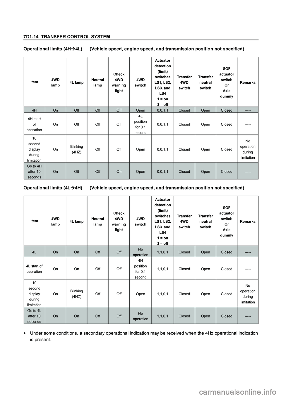
Operational limits (4H�
�� �4L) (Vehicle speed, engine speed, and transmission position not specified)
Item 4WD
lamp 4L lampNeutral
lamp Check
4WD
warning
light 4WD
switch Actuator
detection
(limit)
switches
LS1, LS2,
LS3. and
LS4
1 = on
2 = off Transfer
4WD
switch Transfer
neutral
switch SOF
actuator
switch
Or
Axle
dummyRemarks
4H On Off Off Off Open 0,0,1,1 Closed Open Closed -----
4H start
of
operation On Off Off Off 4L
position
for 0.1
second 0,0,1,1 Closed Open Closed -----
10
second
display
during
limitation On Blinking
(4HZ) Off Off Open 0,0,1,1 Closed Open Closed No
operation
during
limitation
Go to 4H
after 10
seconds
On Off Off Off Open 0,0,1,1 Closed Open Closed -----
Operational limits (4L�
�� �
4H) (Vehicle speed, engine speed, and transmission position not specified)
Item 4WD
lamp 4L lampNeutral
lamp Check
4WD
warning
light 4WD
switch Actuator
detection
(limit)
switches
LS1, LS2,
LS3. and
LS4
1 = on
2 = off Transfer
4WD
switch Transfer
neutral
switch SOF
actuator
switch
Or
Axle
dummyRemarks
4L On On Off Off No
operation1,1,0,1 Closed Open Closed -----
4L start of
operation On On Off Off 4H
position
for 0.1
second 1,1,0,1 Closed Open Closed -----
10
second
display
during
limitation On Blinking
(4HZ) Off Off Open 1,1,0,1 Closed Open Closed No
operation
during
limitation
Go to 4L
after 10
seconds
On On Off Off No
operation1,1,0,1 Closed Open Closed -----
�
Under some conditions, a secondary operational indication may be received when the 4Hz operational indication
is present.
Page 3643 of 4264

TRANSFER CONTROL SYSTEM 7D1-17
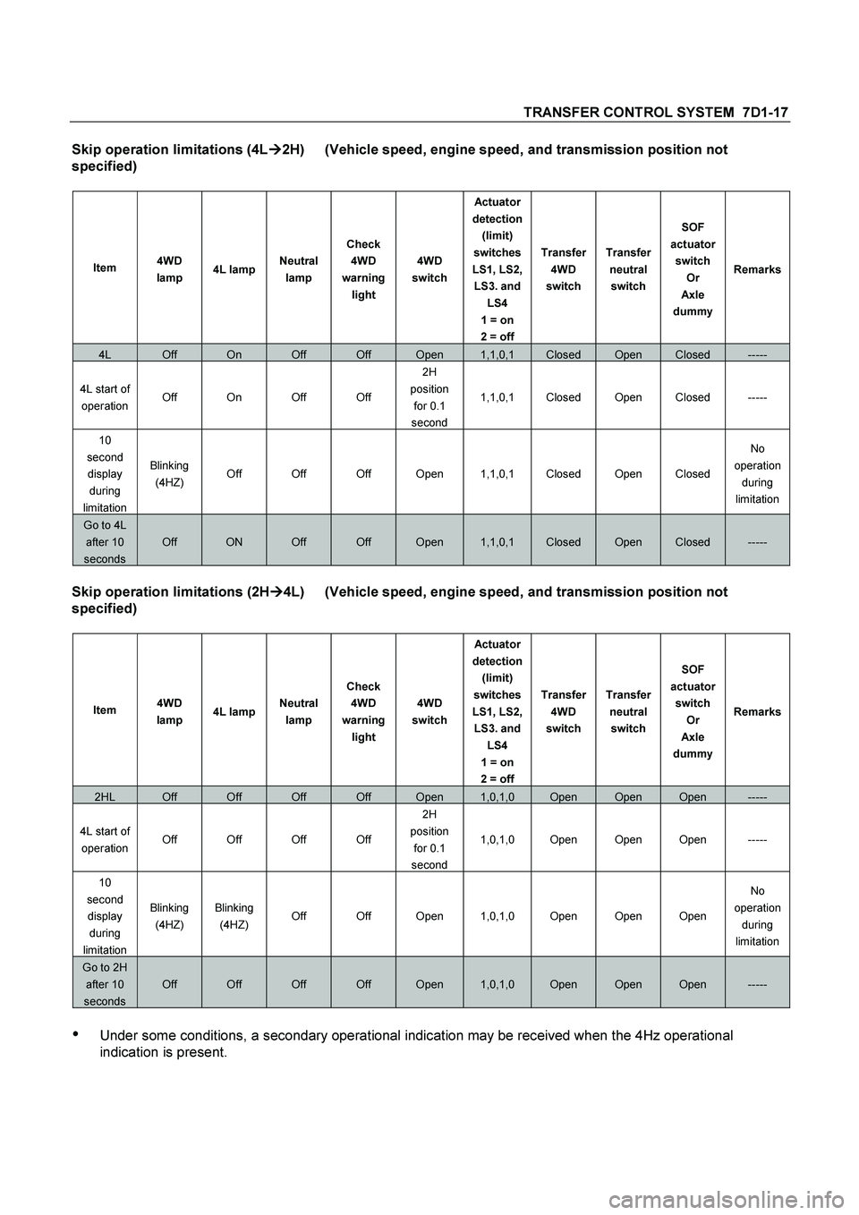
Skip operation limitations (4L�
�� �2H) (Vehicle speed, engine speed, and transmission position not
specified)
Item 4WD
lamp 4L lampNeutral
lamp Check
4WD
warning
light 4WD
switch Actuator
detection
(limit)
switches
LS1, LS2,
LS3. and
LS4
1 = on
2 = off Transfer
4WD
switch Transfer
neutral
switch SOF
actuator
switch
Or
Axle
dummyRemarks
4L Off On Off Off Open 1,1,0,1 Closed Open Closed -----
4L start of
operation Off On Off Off 2H
position
for 0.1
second 1,1,0,1 Closed Open Closed -----
10
second
display
during
limitation Blinking
(4HZ) Off Off Off Open 1,1,0,1 Closed Open Closed No
operation
during
limitation
Go to 4L
after 10
seconds
Off ON Off Off Open 1,1,0,1 Closed Open Closed -----
Skip operation limitations (2H�
�� �4L) (Vehicle speed, engine speed, and transmission position not
specified)
Item 4WD
lamp 4L lampNeutral
lamp Check
4WD
warning
light 4WD
switch Actuator
detection
(limit)
switches
LS1, LS2,
LS3. and
LS4
1 = on
2 = off Transfer
4WD
switch Transfer
neutral
switch SOF
actuator
switch
Or
Axle
dummyRemarks
2HL Off Off Off Off Open 1,0,1,0 Open Open Open -----
4L start of
operation Off Off Off Off 2H
position
for 0.1
second 1,0,1,0 Open Open Open -----
10
second
display
during
limitation Blinking
(4HZ) Blinking
(4HZ) Off Off Open 1,0,1,0 Open Open Open No
operation
during
limitation
Go to 2H
after 10
seconds
Off Off Off Off Open 1,0,1,0 Open Open Open -----
��Under some conditions, a secondary operational indication may be received when the 4Hz operational
indication is present.
Page 3645 of 4264
TRANSFER CONTROL SYSTEM 7D1-19
Item 4WD
lamp 4L lampNeutral
lamp Check
4WD
warning
light 4WD
switch Actuator
detectio
n (limit)
switches
LS1,
LS2,
LS3. and
LS4
1 = on
2 = off Transfer
4WD
switch Transfer
neutral
switch SOF
actuator
switch
Or
Axle
dummy Remarks
During
operation
(4H
waiting) Off Blinking
(2HZ) Off Off No
operation0,0,1,1 Closed Closed Closed 4L to 4H
while
waiting
During
operation
(Axle) Blinking
(2HZ) Off Off Off No
operation0,1,1,1
0,1,1,0
0,0,1,0
1,1,1,0 Closed Open Closed 2H to 4H
while
driving
During
operation
(Axle) Blinking
(2HZ) Off Off Off No
operation0,1,1,1
0,1,1,0
0,0,1,0
1,1,1,0 Open Open Closed Axle
driving
Axle
waiting
Blinking
(2HZ) Off Off Off No
operation1,0,1,0 Open Open Closed -----
2H Off Off Off Off No
operation1,0,1,0 Open Open Open -----
�
Operational restrictions (vehicle speed, engine speed, and transmission position) are applicable to transfer
shifts in both directions (H��
Neutral��
L).
Page 3648 of 4264

7D1-22 TRANSFER CONTROL SYSTEM
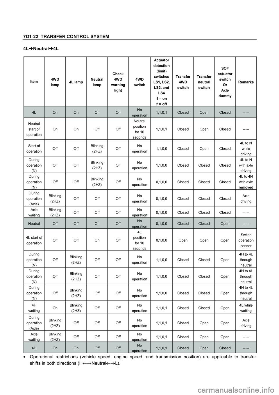
4L�
�� �Neutral�
�� �4L
Item 4WD
lamp 4L lampNeutral
lamp Check
4WD
warning
light 4WD
switch Actuator
detection
(limit)
switches
LS1, LS2,
LS3. and
LS4
1 = on
2 = off Transfer
4WD
switch Transfer
neutral
switch SOF
actuator
switch
Or
Axle
dummyRemarks
4L On On Off Off No
operation1,1,0,1 Closed Open Closed -----
Neutral
start of
operation On On Off Off Neutral
position
for 10
seconds 1,1,0,1 Closed Open Closed -----
Start of
operation Off Off Blinking
(2HZ) Off No
operation1,1,0,0 Closed Open Closed 4L to N
while
driving
During
operation
(N) Off Off Blinking
(2HZ) Off No
operation1,1,0,0 Closed Closed Closed 4L to N
with axle
driving
During
operation
(N) Off Off Blinking
(2HZ) Off No
operation0,1,0,0 Closed Closed Closed 4L to 4N
with axle
removed
During
operation
(Axle) Blinking
(2HZ) Off Off Off No
operation0,1,0,0 Closed Closed Closed Axle
driving
Axle
waiting
Blinking
(2HZ) Off Off Off No
operation0,1,0,0 Closed Closed Closed -----
Neutral Off Off On Off No
operation0,1,0,0 Closed Closed Open -----
4L start of
operation Off Off On Off 4L
position
for 10
seconds 0,1,0,0 Open Open Open Switch
operation
sensor
During
operation
(N) Off Blinking
(2HZ) Off Off No
operation1,1,0,0 Closed Closed Open 4H to 4L
through
neutral
During
operation
(N) Off Blinking
(2HZ) Off Off No
operation1,1,0,0 Closed Closed Open 4H to 4L
through
neutral
During
operation
(N) Off Blinking
(2HZ) Off Off No
operation1,1,0,0 Closed Closed Open 4H to 4L
through
neutral
4H
waiting On Blinking
(2HZ) Off Off No
operation1,1,0,1 Closed Closed Open 4L while
waiting
During
operation
(Axle) Blinking
(2HZ) Off Off Off No
operation1,1,0,1 Closed Open Open Axle
driving
Axle
waiting
Blinking
(2HZ) Off Off Off No
operation1,1,0,1 Closed Open Open -----
4H On On Off Off No
operation1,1,0,1 Closed Open Closed -----
�
Operational restrictions (vehicle speed, engine speed, and transmission position) are applicable to transfer
shifts in both directions (H��
Neutral��
L).
Page 3674 of 4264

7D1-48 TRANSFER CONTROL SYSTEM
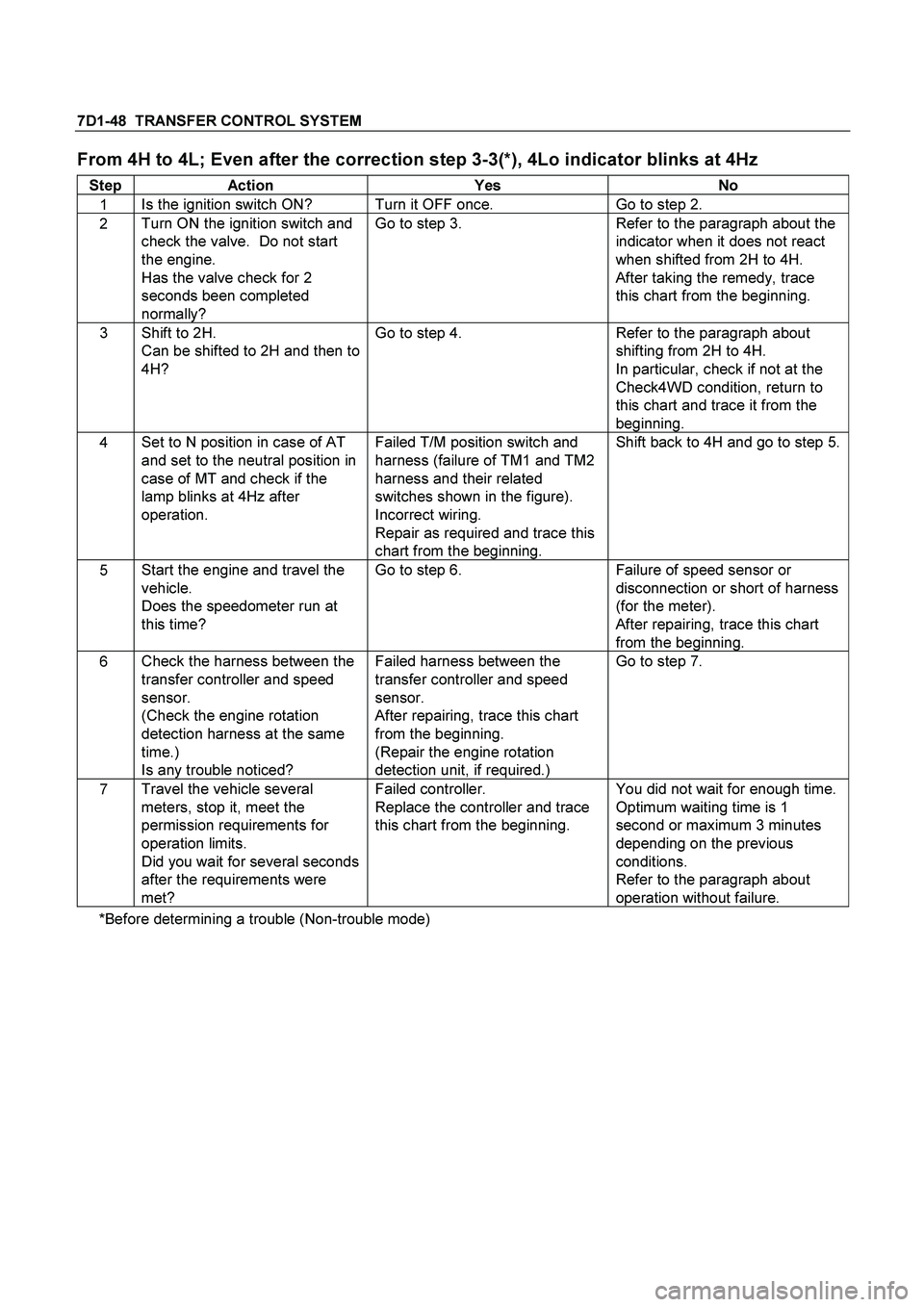
From 4H to 4L; Even after the correction step 3-3(*), 4Lo indicator blinks at 4Hz
Step Action Yes No
1 Is the ignition switch ON? Turn it OFF once. Go to step 2.
2 Turn ON the ignition switch and
check the valve. Do not start
the engine.
Has the valve check for 2
seconds been completed
normally? Go to step 3. Refer to the paragraph about the
indicator when it does not react
when shifted from 2H to 4H.
After taking the remedy, trace
this chart from the beginning.
3 Shift to 2H.
Can be shifted to 2H and then to
4H? Go to step 4. Refer to the paragraph about
shifting from 2H to 4H.
In particular, check if not at the
Check4WD condition, return to
this chart and trace it from the
beginning.
4 Set to N position in case of AT
and set to the neutral position in
case of MT and check if the
lamp blinks at 4Hz after
operation.
Failed T/M position switch and
harness (failure of TM1 and TM2
harness and their related
switches shown in the figure).
Incorrect wiring.
Repair as required and trace this
chart from the beginning. Shift back to 4H and go to step 5.
5 Start the engine and travel the
vehicle.
Does the speedometer run at
this time? Go to step 6. Failure of speed sensor or
disconnection or short of harness
(for the meter).
After repairing, trace this chart
from the beginning.
6 Check the harness between the
transfer controller and speed
sensor.
(Check the engine rotation
detection harness at the same
time.)
Is any trouble noticed? Failed harness between the
transfer controller and speed
sensor.
After repairing, trace this chart
from the beginning.
(Repair the engine rotation
detection unit, if required.) Go to step 7.
7 Travel the vehicle several
meters, stop it, meet the
permission requirements for
operation limits.
Did you wait for several seconds
after the requirements were
met? Failed controller.
Replace the controller and trace
this chart from the beginning. You did not wait for enough time.
Optimum waiting time is 1
second or maximum 3 minutes
depending on the previous
conditions.
Refer to the paragraph about
operation without failure.
*Before determining a trouble (Non-trouble mode)