Page 3044 of 4264
 Check for refrigerant leaks by using a HFC-134a leak
detector.
�
A fully charged system is indicated by the sight glass on
the receiver/drier being free")
1-34 HEATER AND AIR CONDITIONING
9) Check for refrigerant leaks by using a HFC-134a leak
detector.
�
A fully charged system is indicated by the sight glass on
the receiver/drier being free of any bubbles (Refer to
"Reading Sight Glass").
�
Check the high and low pressure value of the manifold
gauge. (Refer to “CHECKING REFRIGERANT SYSTEM
WITH MAINFOLD GAUGE” in SERVICE
INFORMATION.)
Immediately after charging refrigerant, both high and low
pressures are slightly high and to the left of the gauge, but they
settle down to the guide pressure valves as shown below:
� Ambient temperature; 30�35�C (86�95�F)
�
Guide pressure
High-pressure side;
Approx. 1373�
1670 kPa (14�
17 kg/cm
2 / 199�
242 PSI)
Low-pressure side;
Approx. 127�
245 kPa (1.3�
2.5 kg/cm
2 / 18�
36 PSI)
10) Close the low pressure hand valve and charge valve of the
refrigerant container.
11) Stop the air conditioning and the engine.
12) Disconnect the high and low pressure hoses from the
manifold gauge fittings.
Page 3045 of 4264

HEATER AND AIR CONDITIONING 1-35
Reading Sight Glass
High and low
pressure pipe
temperature The high pressure
pipe is hot and the
low pressure pipe
is cold. There is a
distinct difference
in temperature
between them. The high pressure
pipe is warm and
the low pressure
pipe is cool. There
is no great
difference in
temperature
between them. There is little
difference in
temperature
between the high
pressure pipe and
the low pressure
pipe. The high pressure
pipe is hot and the
low pressure pipe
is slightly warm.
There is a
difference in
temperature
between them.
Sight glass
condition Almost transparent.
A flow of bubbles
can be seen, but
they disappear
when the throttle is
opened.
A flow of bubbles
always can be
seen. It appears
sometimes
transparent, and
sometimes frothy.
Something like fog
faintly can be seen.
Evan at idle with
the fan at "HI" (with
the window fully
open), the bubbles
cannot be seen.
Air conditioning
cycle condition
OK NG
(Not enough
refrigerant) NG
(Almost no
refrigerant) NG
(Too much
refrigerant)
The sight glass provides accurate diagnosis only under the following conditions.
If the vehicle can be tested under these conditions, check the sight glass appearance and compare to the chart.
* Engine speed Idling
* A/C switch "ON"
* Blower fan operating at highest speed
* Air source selector lever at "RECIRC"
* Temperature control knob at coldest position
* Ambient temperature below 35�
C (95�
F) and humidity below 70% (See NOTE 1)
* High side pressure less than 1470 kPa (15 kg/cm
2 / 213 PSI) (See NOTE 2)
NOTE 1
If the vehicle cannot be moved to a testing location that meets these specifications, then the sight glass cannot be
used for diagnosis. You must discharge and recover the refrigerant, then recharge the system with the specified
amount of refrigerant. Then continue checking the system performance.
NOTE 2
If the high side pressure is greater than stated, the sight glass cannot be used for diagnosis. You must discharge
and recover the refrigerant, then recharge the system with the specified amount of refrigerant. Then continue
checking system performance.
Page 3058 of 4264
 of oil is charged in compressor (service
parts). So it is necessary to drain the prop")
1-48 HEATER AND AIR CONDITIONING
Checking and Adjusting for Compressor
Replacement
180 cm3 (5.0 lmp fl oz) of oil is charged in compressor (service
parts). So it is necessary to drain the proper amount of oil from
the new compressor.
1) Perform oil return operation.
2) Discharge refrigerant and remove the compressor.
3) Drain the compressor oil and measure the extracted oil.
4) Check the compressor oil for contamination.
5) Adjust oil level as required.
Amount of oil drained
From used compressor Draining amount of oil
From new compressor
less than
90 cm
3 (2.5 lmp fl oz) Some as drained
amount
more than
90 cm
3 (2.5 lmp fl oz) 90 cm
3 (2.5 lmp fl oz)
6) Evacuate, charge and perform oil return operation.
7) Check system operation.
CONTAMINATION OF COMPRESSOR OIL
Unlike engine oil, no cleaning agent is added to the
compressor oil. Even is the compressor runs for a long period
of time (approximately 1 season), the oil never becomes
contaminated as long as there is nothing wrong with the
compressor or its method of use.
Inspect the extracted oil for any of the following
conditions:
� The capacity of the oil has increased.
� The oil has changed color to red.
�
Foreign substances, metal powder, etc., are present in the
oil.
If any of these conditions exists, compressor oil is
contaminated. Whenever contaminated compressor oil is
discovered, the receiver/drier must be replaced.
Page 3059 of 4264

HEATER AND AIR CONDITIONING 1-49
OIL RETURN OPERATION
There is close affinity between the oil and the refrigerant.
During normal operation, part of the oil recirculates with the
refrigerant in the system.
When checking the amount of oil in the system, or replacing
any component of the system, the compressor must be run in
advance for oil return operation. The procedure is as follows:
1) Open the all doors and engine hood.
2) Start the engine and A/C switch is "ON" and Set the fan
control knob at its highest position.
3) Run the compressor for more than 20 minutes between
800 and 1,000 rpm in order to operate the system.
4) Stop the engine.
REPLACEMENT OF COMPONENT PARTS
When replacing system component parts, supply the following
amount of oil to the component parts to be installed.
Component parts to be installed Amount of oil
Evaporator 50 cm3 (1.7 fl.oz.)
Condenser 30 cm3 (1.0 fl.oz.)
Receiver/drier 30 cm3 (1.0 fl.oz.)
Refrigerant line (One piece) 10 cm3 (0.3 fl.oz.)
Refrigeration oil must be replenished if more than two parts
are removed at the same time. After installing these
components, check compressor oil.
Page 3090 of 4264
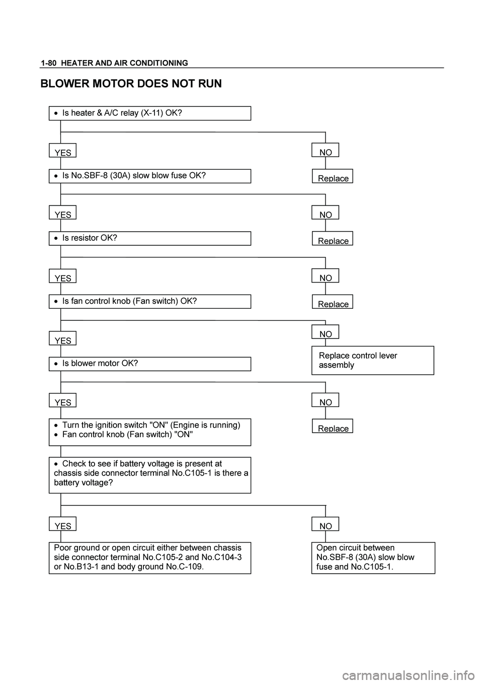
1-80 HEATER AND AIR CONDITIONING
BLOWER MOTOR DOES NOT RUN
Replace
YES
� Is No.SBF-8 (30A) slow blow fuse OK?
��Is heater & A/C relay (X-11) OK?
YES
� Is resistor OK?
YES
� Is fan control knob (Fan switch) OK?
YES
YES
� Check to see if battery voltage is present at
chassis side connector terminal No.C105-1 is there a
battery voltage?
� Turn the ignition switch "ON" (Engine is running)
� Fan control knob (Fan switch) "ON"
� Is blower motor OK?
YES
Poor ground or open circuit either between chassis
side connector terminal No.C105-2 and No.C104-3
or No.B13-1 and body ground No.C-109.
NO
Replace
NO
Replace
NO
NO
Replace control lever
assembly
Replace
NO
NO
Open circuit between
No.SBF-8 (30A) slow blow
fuse and No.C105-1.
Page 3094 of 4264
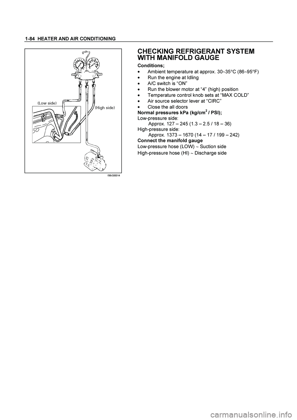
1-84 HEATER AND AIR CONDITIONING
f06r300014
CHECKING REFRIGERANT SYSTEM
WITH MANIFOLD GAUGE
Conditions;
��
Ambient temperature at approx. 30�
35�
C (86�
95�
F)
��
Run the engine at Idling
��A/C switch is “ON”
��
Run the blower motor at “4” (high) position
��
Temperature control knob sets at “MAX COLD”
��
Air source selector lever at “CIRC”
��
Close the all doors
Normal pressures kPa (kg/cm
2 / PSI);
Low-pressure side:
Approx. 127 – 245 (1.3 – 2.5 / 18 – 36)
High-pressure side:
Approx. 1373 – 1670 (14 – 17 / 199 – 242)
Connect the manifold gauge
Low-pressure hose (LOW) � Suction side
High-pressure hose (HI) � Discharge side
Page 3179 of 4264
MANUAL TRANSMISSION 7B1-15
C24NE
RTW37BLF0002
220RS006
5. Apply a force of about 113N (26 Ib) to the tip of the
shift fork in the direction of the transmission to
engage the clutch pressure plate and release
bearing. (6VE1 only)
NOTE: A clicking sound is heard when the release
bearing and the tip of the diaphragm spring engage
each other.
Check to see if they are securely engaged by pushing
the tip of the shift fork toward the engine while applying
a force of about 25 N (5.5 lb). If the shift fork will not
move, then they are securely engaged.
Page 3208 of 4264

7B1-44 MANUAL TRANSMISSION
Clutch Hub Spline Play
� Set a dial indicator to the clutch hub to be
measured.
226RS042
�
Move the clutch hub as far as possible to both the
right and the left.
Note the dial indicator reading.
If the measured value exceeds the specified limit,
the clutch hub must be replaced.
Clutch Hub Spline Play
Standard Limit
1st-2nd
3rd-4th 0 - 0.1 mm
(0 - 0.004 in) 0.2 mm
(0.008 in)
Rev. 5th 0 - 0.2 mm
(0 - 0.008 in) 0.3 mm
(0.012 in)
Ball Bearing Play
�
Use a dial indicator to measure the ball bearing play.
Ball Bearing Play
Limit: 0.2 mm (0.008 in)
226RS043
Reassembly
1. Install center roller bearing (29) to counter gear
shaft (30).
�
Apply engine oil to the bearing inner and outer
circumferences.
� Install the roller bearing in the proper direction.
NOTE: Check that outer race moves only in the
direction of arrow.
226RS044
2. Install front roller bearing (28) by performing the
following steps.
� Use bearing installer 5-8840-2194-0 to install the
front roller bearing inner race to the counter gear
shaft (30).
�
Install the outer race and roller assembly.
The snap ring groove must be facing the
transmission front side.
 to the tip of the
shift fork in the direction of the transmission to
engage the clutch pres")