2004 INFINITI QX56 low oil pressure
[x] Cancel search: low oil pressurePage 2782 of 3371

HYDRAULIC LINE
PS-31
C
D
E
F
H
I
J
K
L
MA
B
PS
Revision: August 20072004 QX56
HYDRAULIC LINEPFP:49721
Removal and InstallationEGS000MZ
Refer to the following illustration for hydralic line removal.
1. Reservoir tank 2. Suction hose 3. High pressure hose
4. Oil cooler 5. Steering gear assembly 6. Reservoir tank bracket
7. Eye bolt
WGIA0096E
Page 2786 of 3371

SERVICE DATA AND SPECIFICATIONS (SDS)
PS-35
C
D
E
F
H
I
J
K
L
MA
B
PS
Revision: August 20072004 QX56
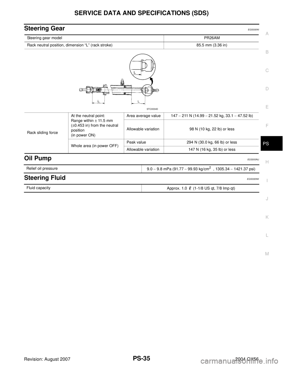
Steering GearEGS000NI
Oil PumpEG S0 0 0NJ
Steering FluidEGS000NK
Steering gear modelPR26AM
Rack neutral position, dimension “L” (rack stroke) 85.5 mm (3.36 in)
Rack sliding forceAt the neutral point:
Range within ± 11.5 mm
(±0.453 in) from the neutral
position
(in power ON)Area average value 147 − 211 N (14.99 − 21.52 kg, 33.1 − 47.52 lb)
Allowable variation 98 N (10 kg, 22 lb) or less
Whole area (in power OFF)Peak value 294 N (30.0 kg, 66 lb) or less
Allowable variation 147 N (16 kg, 35 lb) or less
STC0034D
Relief oil pressure
9.0 − 9.8 mPa (91.77 − 99.93 kg/cm2 , 1305.34 − 1421.37 psi)
Fluid capacity
Approx. 1.0 (1-1/8 US qt, 7/8 Imp qt)
Page 2890 of 3371

REAR SUSPENSION MEMBER
RSU-31
C
D
F
G
H
I
J
K
L
MA
B
RSU
Revision: August 20072004 QX56
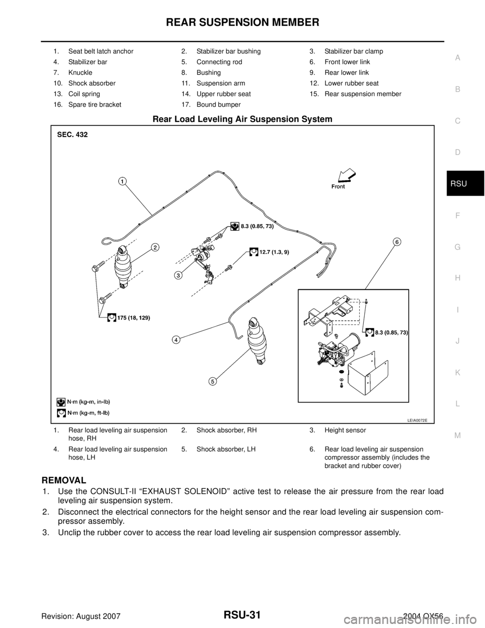
Rear Load Leveling Air Suspension System
REMOVAL
1. Use the CONSULT-II “EXHAUST SOLENOID” active test to release the air pressure from the rear load
leveling air suspension system.
2. Disconnect the electrical connectors for the height sensor and the rear load leveling air suspension com-
pressor assembly.
3. Unclip the rubber cover to access the rear load leveling air suspension compressor assembly.
1. Seat belt latch anchor 2. Stabilizer bar bushing 3. Stabilizer bar clamp
4. Stabilizer bar 5. Connecting rod 6. Front lower link
7. Knuckle 8. Bushing 9. Rear lower link
10. Shock absorber 11. Suspension arm 12. Lower rubber seat
13. Coil spring 14. Upper rubber seat 15. Rear suspension member
16. Spare tire bracket 17. Bound bumper
LEIA0072E
1. Rear load leveling air suspension
hose, RH2. Shock absorber, RH 3. Height sensor
4. Rear load leveling air suspension
hose, LH5. Shock absorber, LH 6. Rear load leveling air suspension
compressor assembly (includes the
bracket and rubber cover)
Page 2898 of 3371

REAR LOWER LINK & COIL SPRING
RSU-39
C
D
F
G
H
I
J
K
L
MA
B
RSU
Revision: August 20072004 QX56
REAR LOWER LINK & COIL SPRINGPFP:551B0
Removal and Installation EES0011P
REMOVAL
1. Remove the wheel and tire assembly using power tool. Refer to WT-6, "Rotation" .
2. Use CONSULT-II "EXHAUST SOLENOID" active test to release the air pressure from the rear load level-
ing air suspension system.
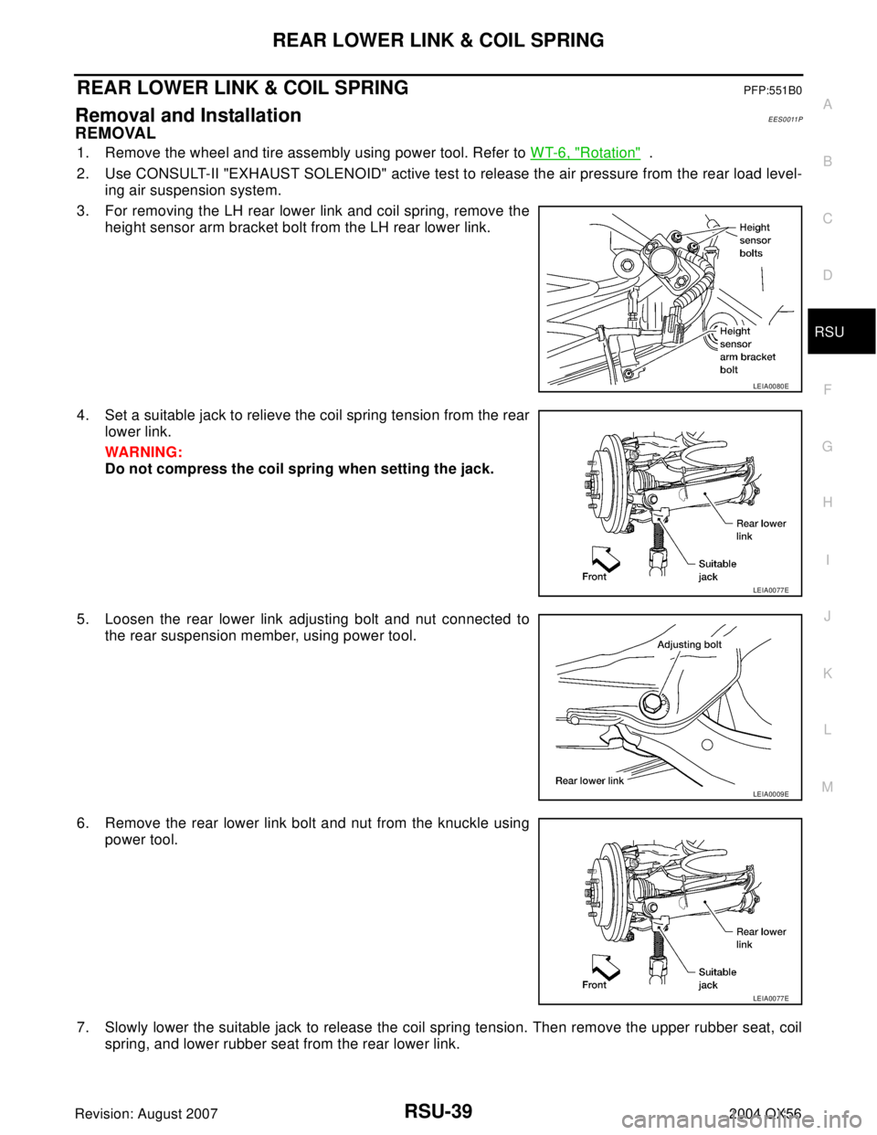
3. For removing the LH rear lower link and coil spring, remove the
height sensor arm bracket bolt from the LH rear lower link.
4. Set a suitable jack to relieve the coil spring tension from the rear
lower link.
WAR NIN G:
Do not compress the coil spring when setting the jack.
5. Loosen the rear lower link adjusting bolt and nut connected to
the rear suspension member, using power tool.
6. Remove the rear lower link bolt and nut from the knuckle using
power tool.
7. Slowly lower the suitable jack to release the coil spring tension. Then remove the upper rubber seat, coil
spring, and lower rubber seat from the rear lower link.
LEIA0080E
LEIA0077E
LEIA0009E
LEIA0077E
Page 3127 of 3371

TF-2Revision: August 20072004 QX56 SWITCH ..................................................................... 62
Diagnostic Procedure ............................................. 62
TRANSFER MOTOR AND TRANSFER MOTOR
RELAY ....................................................................... 64
Diagnostic Procedure ............................................. 64
TRANSFER FLUID TEMPERATURE SENSOR ....... 66
Diagnostic Procedure ............................................. 66
ATP SWITCH, WAIT DETECTION SWITCH AND
NEUTRAL-4LO SWITCH .......................................... 69
Diagnostic Procedure ............................................. 69
CLUTCH PRESSURE SWITCH ................................ 72
Diagnostic Procedure ............................................. 72
LINE PRESSURE SWITCH ....................................... 74
Diagnostic Procedure ............................................. 74
DATA ERASE/DISPLAY ............................................ 76
Diagnostic Procedure ............................................. 76
SHIFT ACTUATOR ................................................... 77
Diagnostic Procedure ............................................. 77
SHIFT ACTUATOR POSITION SWITCH .................. 80
Diagnostic Procedure ............................................. 80
SHIFT ACTUATOR CIRCUIT .................................... 82
Diagnostic Procedure ............................................. 82
TROUBLE DIAGNOSES FOR SYMPTOMS ............. 85
Symptom 1. 4WD Shift Indicator Lamp Does Not
Turn ON (Although the ignition switch is turned ON,
all the 4WD indicator lamps do not turn ON for 1
second) ................................................................... 85
Symptom 2. 4WD Warning Lamp Does Not Turn ON
(Although the ignition switch is turned ON, the 4WD
warning lamp does not turn ON) ............................. 87
Symptom 3. 4WD Shift Indicator Lamp Does Not
Turn OFF (When 4WD shift switch is set from 4H
to 4LO, all the 4WD shift indicator lamps do not turn
off) ........................................................................... 88
Symptom 4. ATP Warning Lamp Does Not Turn ON
(When 4WD shift switch is set from 4H to 4LO with
the A/T selector lever in P position, the ATP warning
lamp does not turn on) ............................................ 89
Symptom 5. 4LO Indicator Lamp Does Not Turn ON
(When 4WD shift switch is set from 4H to 4LO posi-
tion, 4LO indicator lamp does not turn ON) ............ 90
Symptom 6. 4WD Shift Indicator Lamp Does Not
Indicate “LOCK” (When 4WD shift switch is set to
“4H”, 4WD shift indicator lamp does not indicate
“LOCK”) .................................................................. 91
Symptom 7. 4WD Shift Indicator Lamp Repeats
Flickering (4WD Shift Indicator Lamp Keeps Flick-
ering) ...................................................................... 92
Symptom 8. Tight Corner Braking Symptom (Tight
Corner Braking Symptom Occurs-Hydraulic Sys-
tem Failure) ............................................................ 93
Symptom 9. 4WD System Does Not Operate (The
Vehicle Cannot Be Put Into 4WD Mode-Hydraulic
System Failure) ...................................................... 94
Component Inspection ............................................ 95
4WD SHIFT SWITCH .......................................... 95
2-4WD SHIFT SOLENOID VALVE AND TRANS-
FER FLUID TEMPERATURE SENSOR .............. 95
4WD SOLENOID VALVE, CLUTCH PRESSURE SWITCH AND LINE PRESSURE SWITCH .........95
TRANSFER DROPPING RESISTOR ..................96
ATP SWITCH, NEUTRAL-4LO SWITCH AND
WAIT DETECTION SWITCH ...............................96
TRANSFER MOTOR ...........................................96
TRANSFER MOTOR RELAY ...............................97
TRANSFER SHIFT RELAY (HIGH & LOW) .........97
ACTUATOR AND ACTUATOR POSITION
SWITCH ...............................................................97
TRANSFER CONTROL UNIT ...................................98
Removal and Installation .........................................98
REMOVAL ............................................................98
INSTALLATION ....................................................98
FRONT OIL SEAL .....................................................99
Removal and Installation .........................................99
REMOVAL ............................................................99
INSTALLATION .................................................. 100
REAR OIL SEAL ..................................................... 101
Removal and Installation ....................................... 101
REMOVAL .......................................................... 101
INSTALLATION .................................................. 101
SIDE OIL SEAL ....................................................... 103
Removal and Installation ....................................... 103
REMOVAL .......................................................... 103
INSTALLATION .................................................. 103
TRANSFER CONTROL DEVICE ............................ 104
Removal and Installation ....................................... 104
AIR BREATHER HOSE ........................................... 105
Removal and Installation ....................................... 105
TRANSFER MOTOR ............................................... 106
Removal and Installation ....................................... 106
REMOVAL .......................................................... 106
INSTALLATION ..................................................... 106
TRANSFER OIL FILTER ......................................... 107
Removal and Installation ....................................... 107
REMOVAL .......................................................... 107
INSTALLATION .................................................. 107
REMOVAL AND INSTALLATION ............................ 109
Removal ................................................................ 109
Installation ............................................................. 109
OVERHAUL .............................................................110
Transfer Components ...........................................110
REAR CASE ............................................................112
Disassembly ..........................................................112
CENTER CASE .......................................................113
Disassembly ..........................................................113
FRONT DRIVE SHAFT AND DRIVE CHAIN .....115
MAINSHAFT AND CLUTCH DRUM ..................116
CLUTCH PISTON ..............................................118
CONTROL VALVE .............................................119
MAINSHAFT REAR BEARING .......................... 122
MAIN OIL PUMP ................................................ 122
SUB OIL PUMP ................................................. 123
OIL FILTER ........................................................ 124
FRONT CASE .......................................................... 125
Disassembly .......................................................... 125
SHIFT ROD COMPONENTS ............................. 125
PLANETARY CARRIER, SUN GEAR AND
INTERNAL GEAR .............................................. 127
Page 3140 of 3371

ALL-MODE 4WD SYSTEM
TF-15
C
E
F
G
H
I
J
K
L
MA
B
TF
Revision: August 20072004 QX56
Description of Electrical PartsEDS0017R
TRANSFER MOTOR
1. The transfer motor drives the sub-oil pump to provide proper lubrication and oil pressure control when the
vehicle is at standstill, during low-speed operations or is being driven in reverse.
2. The main oil pump is operated by the driving force of the mainshaft. In other words, sufficient oil pressure
buildup does not occur when the vehicle is at standstill or during low-speed operations. While the vehicle
is being driven in reverse, the main oil pump rotates in the reverse direction. Therefore the main oil pump
does not discharge oil pressure. During any of the above vehicle operations, the transfer motor drives the
sub-oil pump to compensate for insufficient oil pressure.
3. The transfer motor operates as follows:
1. The motor relay turns OFF in the 2WD mode.
2. The motor relay operates as described in the table below in modes other than the 2WD mode.
Ta b l e 1
Ta b l e 2
NOTE:
OFF (after 2.5 seconds have elapsed.)
4. 4WD shift switch, PNP switch, Neutral-4LO switch, vehicle speed sensor and throttle position sensor are
used in conjunction with the transfer motor.
WAIT DETECTION SWITCH
1. The wait detection switch releases the “booming” torque produced in the propeller shaft. After the release
of the “booming” torque, the wait detection switch helps provide the 4WD lock gear (clutch drum) shifts. A
difference may occur between the operation (“4LO” to “4H” shift only) of the 4WD shift switch and actual
drive mode. At this point, the wait detection switch senses an actual drive mode.
2. The wait detection switch operates as follows:
4WD lock gear (clutch drum) locked: ON
4WD lock gear (clutch drum) released: OFF
3. The wait detection switch senses an actual drive mode and the 4WD shift indicator lamp indicates the
vehicle drive mode.
2-4WD SHIFT SOLENOID VALVE
The 2-4WD shift solenoid valve operates to apply oil pressure to the wet, multiplate clutch, depending on the
drive mode. The driving force is transmitted to the front wheels through the clutch when the vehicle is set in the
4WD mode. Setting the vehicle in the 2WD mode requires no pressure buildup. In other words, pressure force
applied to the wet, multiplate clutch becomes zero.
PNP switch “R” position VFF (Vehicle speed) A/T position Motor relay drive command
ON — R ON
OFF0Positions other than the “P” or
“N” positionsON
—“P” or “N” position (See Table
2.)—
0 < VFF ≤ 50 km/h (31 MPH) — ON
50 km/h (31 MPH) < VFF < 55
km/h (34 MPH)—HOLD
55 km/h (34 MPH) ≤ VFF — OFF
A/T position N-4L SW 4WD modeThrottle position
0 - 0.07/8 0.07/8 - 1/8 1/8 - MAX
NOFFLOCK (4H) ON ON ON
Positions other than
the LOCK position
(2WD or AUTO)See NOTE. HOLD ON
ON — See NOTE. HOLD ON
P——See NOTE.HOLDON
Page 3219 of 3371

TF-94
TROUBLE DIAGNOSES FOR SYMPTOMS
Revision: August 20072004 QX56
Symptom 9. 4WD System Does Not Operate (The Vehicle Cannot Be Put Into
4WD Mode-Hydraulic System Failure)
EDS0018M
1. CHECK INPUT SIGNAL
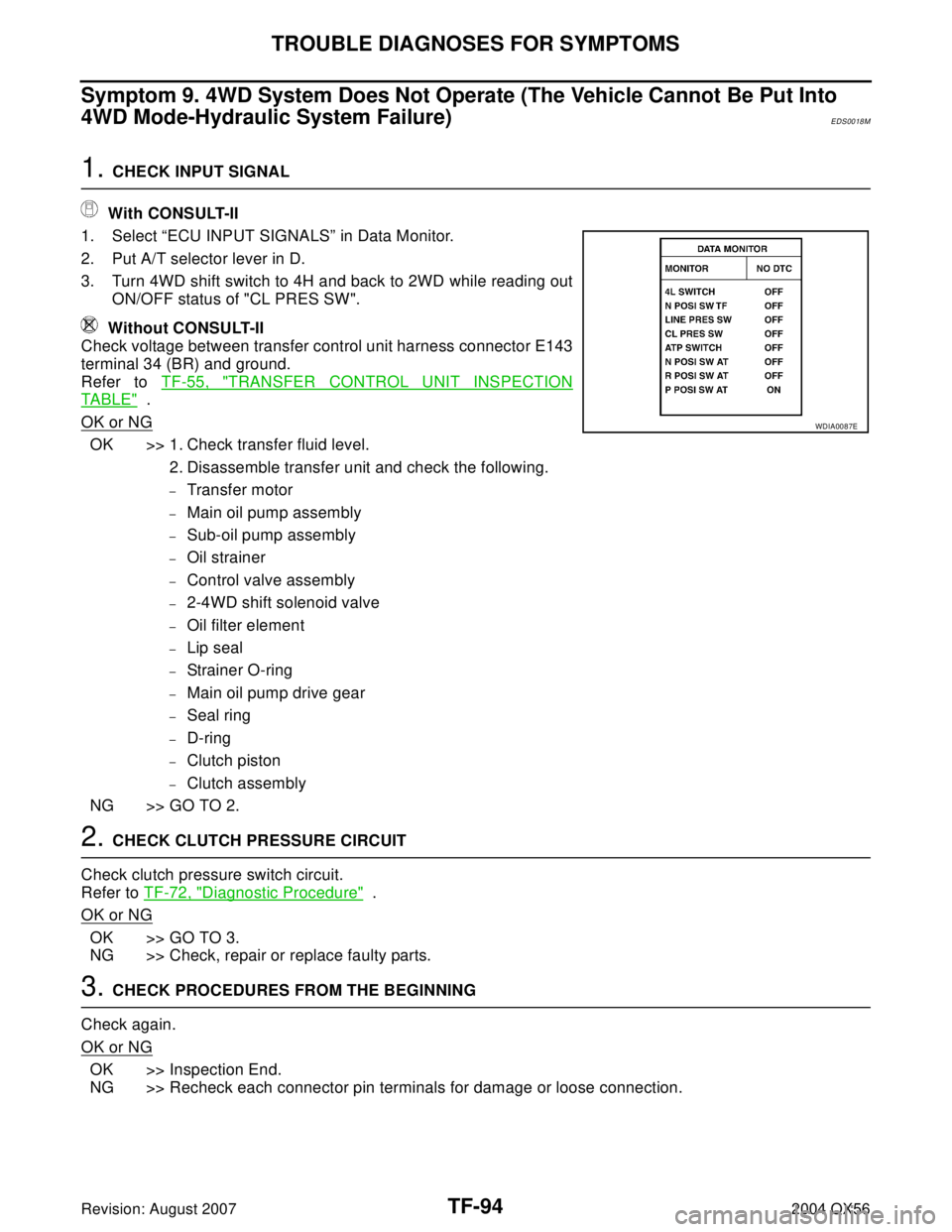
With CONSULT-II
1. Select “ECU INPUT SIGNALS” in Data Monitor.
2. Put A/T selector lever in D.
3. Turn 4WD shift switch to 4H and back to 2WD while reading out
ON/OFF status of "CL PRES SW".
Without CONSULT-II
Check voltage between transfer control unit harness connector E143
terminal 34 (BR) and ground.
Refer to TF-55, "
TRANSFER CONTROL UNIT INSPECTION
TABLE" .
OK or NG
OK >> 1. Check transfer fluid level.
2. Disassemble transfer unit and check the following.
–Transfer motor
–Main oil pump assembly
–Sub-oil pump assembly
–Oil strainer
–Control valve assembly
–2-4WD shift solenoid valve
–Oil filter element
–Lip seal
–Strainer O-ring
–Main oil pump drive gear
–Seal ring
–D-ring
–Clutch piston
–Clutch assembly
NG >> GO TO 2.
2. CHECK CLUTCH PRESSURE CIRCUIT
Check clutch pressure switch circuit.
Refer to TF-72, "
Diagnostic Procedure" .
OK or NG
OK >> GO TO 3.
NG >> Check, repair or replace faulty parts.
3. CHECK PROCEDURES FROM THE BEGINNING
Check again.
OK or NG
OK >> Inspection End.
NG >> Recheck each connector pin terminals for damage or loose connection.
WDIA0087E