Page 585 of 3371

ATC-180
REFRIGERANT LINES
Revision: August 20072004 QX56
2. When checking for leaks, circle each fitting completely with the
probe as shown.
3. Move the probe along each component at a speed of approxi-
mately 25 - 50 mm (1 - 2 in)/second as shown.
CHECKING PROCEDURE
NOTE:
To prevent inaccurate or false readings, make sure there is no refrigerant vapor, shop chemicals, or cigarette
smoke in the vicinity of the vehicle. Perform the leak test in a calm area (low air/wind movement) so that the
leaking refrigerant is not dispersed.
1. Turn the engine OFF.
2. Connect the manifold gauge set (J-39183-C) to the A/C service ports. Refer to ATC-162, "
SETTING OF
SERVICE TOOLS AND EQUIPMENT" .
3. Check if the A/C refrigerant pressure is at least 345 kPa (3.52 kg/cm
2 , 50 psi) above a temperature of
16°C (61°F). If less than specification, recover/evacuate and recharge the system with the specified
amount of refrigerant. Refer to ATC-162, "
HFC-134a (R-134a) Service Procedure" .
NOTE:
At temperatures below 16°C (61°F), leaks may not be detected since the system may not reach 345 kPa
(3.52 kg/cm
2 , 50 psi) pressure.
4. Perform the leak test from the high-pressure side (front A/C compressor discharge “a” to evaporator inlet
“f”, or rear piping connection “l”) to the low-pressure side (front A/C evaporator drain hose “g” to shaft seal
“k”, and rear A/C evaporator drain hose “o” to piping connection “r”). Refer to ATC-164, "
Components" .
Clean the component to be checked and carefully move the electronic refrigerant leak detector probe
completely around the following connections and components.
�Compressor
�Check the high and low-pressure pipe and hose fittings, relief valve, and compressor shaft seal
�Check the liquid tank
�Check the refrigerant pressure sensor
�Check all around the service valves. Check that the service valve caps are tightly screwed on to the
service valves (to prevent leaks).
NOTE:
After removing manifold gauge set (J-39183-C) from the service valves, wipe any residue from the ser-
vice valves to prevent any false readings by the electronic refrigerant leak detector (J-41995).
�Evaporator
With engine OFF, turn blower fan on “High” for at least 15 seconds to dissipate any refrigerant trace in
the heater and cooling unit assembly. Wait a minimum of 10 minutes accumulation time (refer to the
manufacturer's recommended procedure for actual wait time) before inserting the electronic refrigerant
leak detector probe into the heater and cooling unit assembly drain hose.
SHA7 06 E
SHA708EA
Page 1084 of 3371

CO-1
ENGINE COOLING SYSTEM
B ENGINE
CONTENTS
C
D
E
F
G
H
I
J
K
L
M
SECTION CO
A
CO
Revision: August 20072004 QX56 PRECAUTIONS .......................................................... 2
Precautions for Supplemental Restraint System
(SRS) “AIR BAG” and “SEAT BELT PRE-TEN-
SIONER” .................................................................. 2
PREPARATION ........................................................... 3
Special Service Tools ............................................... 3
Commercial Service Tools ........................................ 3
OVERHEATING CAUSE ANALYSIS .......................... 4
Troubleshooting Chart .............................................. 4
COOLING SYSTEM .................................................... 6
Cooling Circuit .......................................................... 6
System Drawing ....................................................... 7
ENGINE COOLANT .................................................... 8
Inspection ................................................................. 8
LEVEL CHECK ..................................................... 8
CHECKING COOLING SYSTEM FOR LEAKS ..... 8
CHECKING RESERVOIR CAP ............................. 8
CHECKING RADIATOR CAP ................................ 8
Changing Engine Coolant ........................................ 8
DRAINING ENGINE COOLANT ........................... 8
REFILLING ENGINE COOLANT .......................... 9
FLUSHING COOLING SYSTEM ........................... 9
RADIATOR ................................................................ 10
Removal and Installation ........................................ 10
REMOVAL ........................................................... 10
INSTALLATION ................................................... 12
INSPECTION AFTER INSTALLATION ............... 12
Checking Radiator .................................................. 12ENGINE COOLING FAN ........................................... 13
Removal and Installation (Crankshaft Driven Type) ... 13
REMOVAL ........................................................... 13
INSPECTION AFTER REMOVAL ....................... 13
INSTALLATION ................................................... 13
INSPECTION AFTER INSTALLATION ................ 13
Removal and Installation (Motor Driven Type) ....... 14
REMOVAL ........................................................... 14
INSTALLATION ................................................... 14
WATER PUMP .......................................................... 15
Removal and Installation ........................................ 15
REMOVAL ........................................................... 15
INSPECTION AFTER REMOVAL ....................... 15
INSTALLATION ................................................... 15
INSPECTION AFTER INSTALLATION ................ 16
THERMOSTAT AND WATER PIPING ...................... 17
Removal and Installation ........................................ 17
REMOVAL ........................................................... 17
INSPECTION AFTER REMOVAL ....................... 18
INSTALLATION ................................................... 18
INSPECTION AFTER INSTALLATION ................ 18
SERVICE DATA AND SPECIFICATIONS (SDS) ...... 19
Standard and Limit .................................................. 19
ENGINE COOLANT CAPACITY (APPROXI-
MATE) .................................................................. 19
THERMOSTAT .................................................... 19
RADIATOR .......................................................... 19
Page 1087 of 3371

CO-4Revision: August 2007
OVERHEATING CAUSE ANALYSIS
2004 QX56
OVERHEATING CAUSE ANALYSISPFP:00012
Troubleshooting ChartEBS00I4T
Symptom Check items
Cooling sys-
tem parts
malfunctionPoor heat transferWater pump malfunction Worn or loose drive belt
— Thermostat stuck closed —
Damaged finsDust contamination or
paper clogging
Physical damage
Clogged radiator cooling
tubeExcess foreign material
(rust, dirt, sand, etc.)
Water cut valve malfunctionExcess foreign material
(rust, dirt, sand, etc.), phys-
ical damage
Reduced air flowCooling fan does not oper-
ate
Fan assembly — High resistance to fan rota-
tion
Damaged fan blades
Damaged radiator shroud — — —
Improper engine coolant
mixture ratio—— —
Poor engine coolant quality — Engine coolant density —
Insufficient engine coolantEngine coolant leaksCooling hoseLoose clamp
Cracked hose
Water pump Poor sealing
Radiator capLoose
Poor sealing
RadiatorO-ring for damage, deterio-
ration or improper fitting
Cracked radiator tank
Cracked radiator core
Reservoir tank Cracked reservoir tank
Overflowing reservoir tankExhaust gas leaks into
cooling systemCylinder head deterioration
Cylinder head gasket dete-
rioration
Page 1089 of 3371
CO-6Revision: August 2007
COOLING SYSTEM
2004 QX56
COOLING SYSTEMPFP:21020
Cooling CircuitEBS00I4U
WBIA0439E
Page 1090 of 3371
COOLING SYSTEM
CO-7
C
D
E
F
G
H
I
J
K
L
MA
CO
Revision: August 20072004 QX56
System DrawingEBS00I4V
WBIA0463E
Page 1091 of 3371

CO-8Revision: August 2007
ENGINE COOLANT
2004 QX56
ENGINE COOLANTPFP:KQ100
InspectionEBS00I4W
LEVEL CHECK
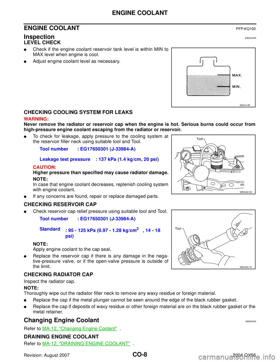
�Check if the engine coolant reservoir tank level is within MIN to
MAX level when engine is cool.
�Adjust engine coolant level as necessary.
CHECKING COOLING SYSTEM FOR LEAKS
WAR NIN G:
Never remove the radiator or reservoir cap when the engine is hot. Serious burns could occur from
high-pressure engine coolant escaping from the radiator or reservoir.
�To check for leakage, apply pressure to the cooling system at
the reservoir filler neck using suitable tool and Tool.
CAUTION:
Higher pressure than specified may cause radiator damage.
NOTE:
In case that engine coolant decreases, replenish cooling system
with engine coolant.
�If any concerns are found, repair or replace damaged parts.
CHECKING RESERVOIR CAP
�Check reservoir cap relief pressure using suitable tool and Tool.
NOTE:
Apply engine coolant to the cap seal.
�Replace the reservoir cap if there is any damage in the nega-
tive-pressure valve, or if the open-valve pressure is outside of
the limit.
CHECKING RADIATOR CAP
Inspect the radiator cap.
NOTE:
Thoroughly wipe out the radiator filler neck to remove any waxy residue or foreign material.
�Replace the cap if the metal plunger cannot be seen around the edge of the black rubber gasket.
�Replace the cap if deposits of waxy residue or other foreign material are on the black rubber gasket or the
metal retainer.
Changing Engine CoolantEBS00I4X
Refer to MA-12, "Changing Engine Coolant" .
DRAINING ENGINE COOLANT
Refer to MA-12, "DRAINING ENGINE COOLANT" .
SM A41 2B
Tool number : EG17650301 (J-33984-A)
Leakage test pressure : 137 kPa (1.4 kg/cm, 20 psi)
WBIA0612E
Tool number : EG17650301 (J-33984-A)
Standard
: 95 - 125 kPa (0.97 - 1.28 kg/cm
2 , 14 - 18
psi)
WBIA0611E
Page 1092 of 3371
ENGINE COOLANT
CO-9
C
D
E
F
G
H
I
J
K
L
MA
CO
Revision: August 20072004 QX56
REFILLING ENGINE COOLANT
Refer to MA-13, "REFILLING ENGINE COOLANT" .
FLUSHING COOLING SYSTEM
Refer to MA-14, "FLUSHING COOLING SYSTEM" .
Page 1095 of 3371

CO-12Revision: August 2007
RADIATOR
2004 QX56
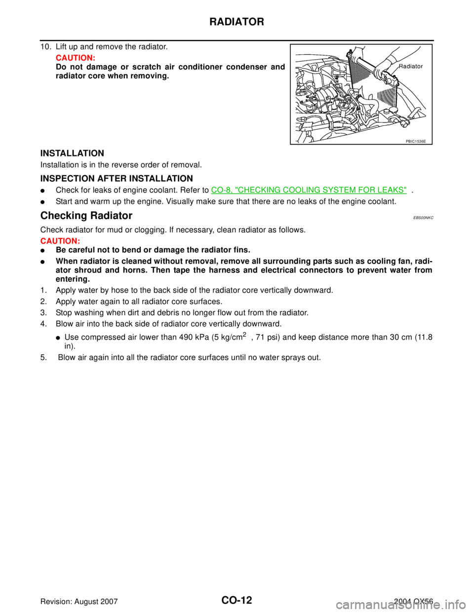
10. Lift up and remove the radiator.
CAUTION:
Do not damage or scratch air conditioner condenser and
radiator core when removing.
INSTALLATION
Installation is in the reverse order of removal.
INSPECTION AFTER INSTALLATION
�Check for leaks of engine coolant. Refer to CO-8, "CHECKING COOLING SYSTEM FOR LEAKS" .
�Start and warm up the engine. Visually make sure that there are no leaks of the engine coolant.
Checking RadiatorEBS00NKC
Check radiator for mud or clogging. If necessary, clean radiator as follows.
CAUTION:
�Be careful not to bend or damage the radiator fins.
�When radiator is cleaned without removal, remove all surrounding parts such as cooling fan, radi-
ator shroud and horns. Then tape the harness and electrical connectors to prevent water from
entering.
1. Apply water by hose to the back side of the radiator core vertically downward.
2. Apply water again to all radiator core surfaces.
3. Stop washing when dirt and debris no longer flow out from the radiator.
4. Blow air into the back side of radiator core vertically downward.
�Use compressed air lower than 490 kPa (5 kg/cm2 , 71 psi) and keep distance more than 30 cm (11.8
in).
5. Blow air again into all the radiator core surfaces until no water sprays out.
PBIC1536E