Page 558 of 3371
AIR MIX DOOR MOTOR
ATC-153
C
D
E
F
G
H
I
K
L
MA
B
AT C
Revision: August 20072004 QX56
AIR MIX DOOR MOTOR PFP:27732
ComponentsEJS002DB
Air Mix Door Motors - Front Heater and Cooling Unit Assembly
Removal and InstallationEJS002DC
FRONT AIR MIX DOOR MOTOR (DRIVER)
Removal
1. Remove the front heater and cooling unit assembly. Refer to ATC-145, "FRONT HEATER AND COOLING
UNIT ASSEMBLY" .
2. Remove the steering member from the front heater and cooling unit assembly.
3. Disconnect the air mix door motor electrical connector.
4. Remove the three screws and remove the air mix door motor.
Installation
Installation is in the reverse order of removal.
LJIA0139E
1. Front heater and cooling unit assembly 2. Intake door motor 3. Air mix door motor (driver)
4. Variable blower control 5. Air mix door motor (passenger) 6. Mode door motor
7. Defroster door motor
Page 559 of 3371
ATC-154
AIR MIX DOOR MOTOR
Revision: August 20072004 QX56
FRONT AIR MIX DOOR MOTOR (PASSENGER)
Removal
1. Remove the front heater and cooling unit assembly. Refer to ATC-145, "FRONT HEATER AND COOLING
UNIT ASSEMBLY" .
2. Remove the steering member from the front heater and cooling unit assembly.
3. Disconnect the air mix door motor electrical connector.
4. Remove the three screws and remove the air mix door motor.
Installation
Installation is in the reverse order of removal.
REAR AIR MIX DOOR MOTOR
Removal
1. Remove the RH rear interior trim panel. Refer to EI-34, "Removal and Installation" .
2. Disconnect the rear air mix door motor electrical connector.
3. Remove the three screws and remove the rear air mix door
motor.
Installation
Installation is in the reverse order of removal.
LJIA0021E
Page 560 of 3371
VARIABLE BLOWER CONTROL
ATC-155
C
D
E
F
G
H
I
K
L
MA
B
AT C
Revision: August 20072004 QX56
VARIABLE BLOWER CONTROLPFP:27200
Removal and InstallationEJS002DD
Variable Blower Control - Front Heater and Cooling Unit Assembly
REMOVAL
1. Remove the front heater and cooling unit assembly. Refer to ATC-145, "FRONT HEATER AND COOLING
UNIT ASSEMBLY" .
2. Remove the steering member from the front heater and cooling unit assembly.
3. Disconnect the variable blower control electrical connector.
4. Remove the two screws and remove the variable blower control.
INSTALLATION
Installation is in the reverse order of removal.
LJIA0139E
1. Front heater and cooling unit assembly 2. Intake door motor 3. Air mix door motor (driver)
4. Variable blower control 5. Air mix door motor (passenger) 6. Mode door motor
7. Defroster door motor
Page 561 of 3371
ATC-156
REAR BLOWER MOTOR RESISTOR
Revision: August 20072004 QX56
REAR BLOWER MOTOR RESISTORPFP:27150
Removal and InstallationEJS002DE
Rear Blower Motor Resistor
REMOVAL
1. Remove the rear RH interior trim panel. Refer to EI-34, "Removal and Installation" .
2. Disconnect the rear blower motor resistor electrical connector.
3. Remove the two screws and remove the rear blower motor resistor.
INSTALLATION
Installation is in the reverse order of removal.
LJIA0055E
1. Rear blower motor 2. Rear blower motor case 3. Rear blower motor resistor
Page 571 of 3371
ATC-166
REFRIGERANT LINES
Revision: August 20072004 QX56
Removal and Installation for CompressorEJS002DJ
A/C Compressor Mounting
REMOVAL
1. Discharge the refrigerant. Refer to ATC-162, "HFC-134a (R-134a) Service Procedure" .
2. Remove the front right wheel and tire assembly. Refer to WT-6, "
Rotation" .
3. Remove the engine under cover and the splash shield using power tool.
4. Remove the engine air cleaner and air ducts. Refer to EM-14, "
REMOVAL" .
5. Remove the drive belt. Refer to EM-12, "
Removal" .
6. Disconnect the compressor electrical connector.
7. Disconnect the high-pressure flexible hose and low-pressure flexible hose from the compressor.
CAUTION:
Cap or wrap the joint of the hose with suitable material such as vinyl tape to avoid the entry of
contaminants.
8. Remove the compressor bolts and nut using power tools.
WJIA0958E
Page 574 of 3371

REFRIGERANT LINES
ATC-169
C
D
E
F
G
H
I
K
L
MA
B
AT C
Revision: August 20072004 QX56
2. Install the magnet coil harness clip using a screwdriver.
3. Install the pulley assembly using Tool and a wrench, then install
the snap ring using snap ring pliers.
4. Install the clutch disc on the compressor shaft, together with the
original shim(s). Press the clutch disc down by hand.
5. Install the clutch pulley bolt using Tool, to prevent the clutch disc
from turning and tighten the bolt to specification. Refer to AT C -
164, "Components" .
CAUTION:
After tightening the clutch pulley bolt, check that the clutch
pulley rotates smoothly.
6. Check the pulley clearance all the way around the clutch disc as
shown.
7. If the specified clearance is not obtained, replace the adjusting
spacer to readjust.
8. Connect the compressor electrical connector.
9. Install the drive belt. Refer to EM-13, "
Installation" .
10. Install the engine under cover and the splash shield.Tool number : — (J-38873-A)
WJIA0368E
WHA184
Tool number : J-44614
WHA229
Clutch disc-to-pulley clearance : 0.3 - 0.6 mm
(0.012 - 0.024 in)
WHA194
Page 577 of 3371

ATC-172
REFRIGERANT LINES
Revision: August 20072004 QX56
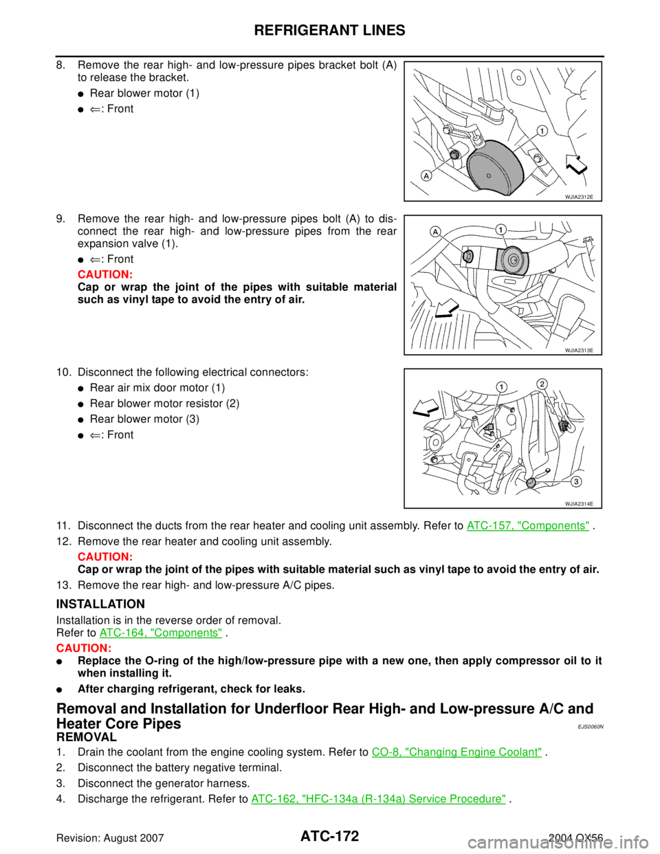
8. Remove the rear high- and low-pressure pipes bracket bolt (A)
to release the bracket.
�Rear blower motor (1)
�⇐: Front
9. Remove the rear high- and low-pressure pipes bolt (A) to dis-
connect the rear high- and low-pressure pipes from the rear
expansion valve (1).
�⇐: Front
CAUTION:
Cap or wrap the joint of the pipes with suitable material
such as vinyl tape to avoid the entry of air.
10. Disconnect the following electrical connectors:
�Rear air mix door motor (1)
�Rear blower motor resistor (2)
�Rear blower motor (3)
�⇐: Front
11. Disconnect the ducts from the rear heater and cooling unit assembly. Refer to ATC-157, "
Components" .
12. Remove the rear heater and cooling unit assembly.
CAUTION:
Cap or wrap the joint of the pipes with suitable material such as vinyl tape to avoid the entry of air.
13. Remove the rear high- and low-pressure A/C pipes.
INSTALLATION
Installation is in the reverse order of removal.
Refer to ATC-164, "
Components" .
CAUTION:
�Replace the O-ring of the high/low-pressure pipe with a new one, then apply compressor oil to it
when installing it.
�After charging refrigerant, check for leaks.
Removal and Installation for Underfloor Rear High- and Low-pressure A/C and
Heater Core Pipes
EJS0060N
REMOVAL
1. Drain the coolant from the engine cooling system. Refer to CO-8, "Changing Engine Coolant" .
2. Disconnect the battery negative terminal.
3. Disconnect the generator harness.
4. Discharge the refrigerant. Refer to ATC-162, "
HFC-134a (R-134a) Service Procedure" .
WJIA2312E
WJIA2313E
WJIA2314E
Page 578 of 3371

REFRIGERANT LINES
ATC-173
C
D
E
F
G
H
I
K
L
MA
B
AT C
Revision: August 20072004 QX56
5. Remove the front and rear bumper fascia. Refer to EI-13, "FRONT BUMPER" (front), EI-15, "REAR
BUMPER" (rear).
6. Reposition the front fender protector out of the way. Refer to EI-23, "
FENDER PROTECTOR" .
7. Disconnect the chassis harness connector.
8. Remove the spare wheel and tire.
9. Remove the tailpipe and tailpipe hanger bracket. Refer to EX-3, "
Removal and Installation" .
10. Remove the seatbelt latch anchor. Refer to RSU-25, "
Components" .
11. Remove the front floor heat shield.
12. Disconnect each end of the underfloor rear high- and low-pressure A/C and heater core pipes. Refer to
ATC-164, "
Components" .
CAUTION:
Cap or wrap the joint of the pipes with suitable material such as vinyl tape to avoid the entry of air.
13. Set two suitable jacks at the RH body mount points to support the vehicle body when it is separated from
the RH side of the frame.
14. Remove the RH body mount bolts. Refer to BL-159, "
Body Mounting" .
15. Use the vehicle hoist to lower the RH side of the frame from the RH side of the body [approximately 305
mm (12 in)] until there is sufficient clearance to remove the underfloor rear high- and low-pressure A/C
and heater core pipes from between the body and the frame.
16. Remove the underfloor rear high- and low-pressure A/C and heater core pipes from the back of the vehi-
cle.
INSTALLATION
Installation is in the reverse order of removal.
Refer to ATC-164, "
Components" .
CAUTION:
�Replace the O-ring of the high/low-pressure pipe with a new one, then apply compressor oil to it
when installing it.
�After charging refrigerant, check for leaks.
Removal and Installation for Refrigerant Pressure SensorEJS002DP
REMOVAL
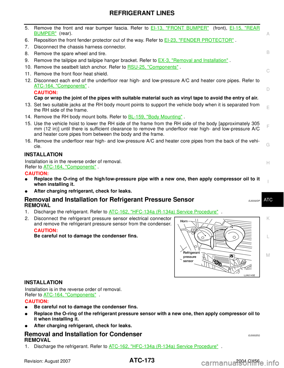
1. Discharge the refrigerant. Refer to ATC-162, "HFC-134a (R-134a) Service Procedure" .
2. Disconnect the refrigerant pressure sensor electrical connector
and remove the refrigerant pressure sensor from the condenser.
CAUTION:
Be careful not to damage the condenser fins.
INSTALLATION
Installation is in the reverse order of removal.
Refer to ATC-164, "
Components" .
CAUTION:
�Be careful not to damage the condenser fins.
�Replace the O-ring of the refrigerant pressure sensor with a new one, then apply compressor oil to
it when installing it.
�After charging refrigerant, check for leaks.
Removal and Installation for CondenserEJ S00 2DQ
REMOVAL
1. Discharge the refrigerant. Refer to ATC-162, "HFC-134a (R-134a) Service Procedure" .
LJIA0145E