Page 1690 of 3371
DTC P1444 EVAP CANISTER PURGE VOLUME CONTROL SOLENOID VALVE
EC-499
C
D
E
F
G
H
I
J
K
L
MA
EC
Revision: August 20072004 QX56
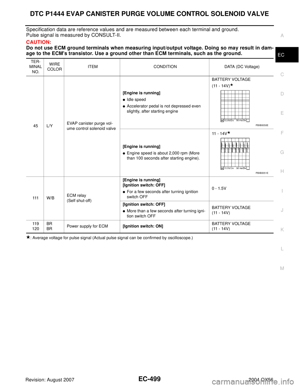
Specification data are reference values and are measured between each terminal and ground.
Pulse signal is measured by CONSULT-II.
CAUTION:
Do not use ECM ground terminals when measuring input/output voltage. Doing so may result in dam-
age to the ECM's transistor. Use a ground other than ECM terminals, such as the ground.
: Average voltage for pulse signal (Actual pulse signal can be confirmed by oscilloscope.)TER-
MINAL
NO.WIRE
COLORITEM CONDITION DATA (DC Voltage)
45 L/YEVAP canister purge vol-
ume control solenoid valve[Engine is running]
�Idle speed
�Accelerator pedal is not depressed even
slightly, after starting engineBATTERY VOLTAGE
(11 - 14V)
[Engine is running]
�Engine speed is about 2,000 rpm (More
than 100 seconds after starting engine).11 - 1 4 V
111 W / BECM relay
(Self shut-off)[Engine is running]
[Ignition switch: OFF]
�For a few seconds after turning ignition
switch OFF0 - 1.5V
[Ignition switch: OFF]
�More than a few seconds after turning igni-
tion switch OFFBATTERY VOLTAGE
(11 - 14V)
11 9
120BR
BRPower supply for ECM[Ignition switch: ON]BATTERY VOLTAGE
(11 - 14V)
PBIB0050E
PBIB0051E
Page 1692 of 3371
DTC P1444 EVAP CANISTER PURGE VOLUME CONTROL SOLENOID VALVE
EC-501
C
D
E
F
G
H
I
J
K
L
MA
EC
Revision: August 20072004 QX56
4. CHECK EVAP CONTROL SYSTEM PRESSURE SENSOR CONNECTOR
1. Disconnect EVAP control system pressure sensor harness connector.
2. Check connectors for water.
OK or NG
OK >> GO TO 5.
NG >> Replace EVAP control system pressure sensor.
5. CHECK EVAP CONTROL SYSTEM PRESSURE SENSOR
Refer to EC-301, "
Component Inspection" .
OK or NG
OK (With CONSULT-II)>>GO TO 6.
OK (Without CONSULT-II)>>GO TO 7.
NG >> Replace EVAP control system pressure sensor.
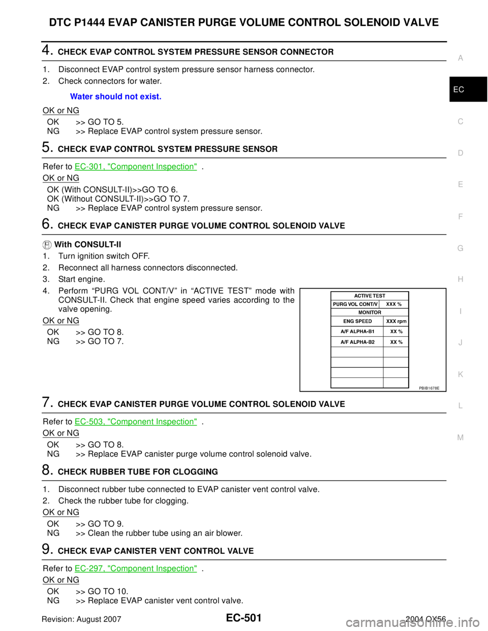
6. CHECK EVAP CANISTER PURGE VOLUME CONTROL SOLENOID VALVE
With CONSULT-II
1. Turn ignition switch OFF.
2. Reconnect all harness connectors disconnected.
3. Start engine.
4. Perform “PURG VOL CONT/V” in “ACTIVE TEST” mode with
CONSULT-II. Check that engine speed varies according to the
valve opening.
OK or NG
OK >> GO TO 8.
NG >> GO TO 7.
7. CHECK EVAP CANISTER PURGE VOLUME CONTROL SOLENOID VALVE
Refer to EC-503, "
Component Inspection" .
OK or NG
OK >> GO TO 8.
NG >> Replace EVAP canister purge volume control solenoid valve.
8. CHECK RUBBER TUBE FOR CLOGGING
1. Disconnect rubber tube connected to EVAP canister vent control valve.
2. Check the rubber tube for clogging.
OK or NG
OK >> GO TO 9.
NG >> Clean the rubber tube using an air blower.
9. CHECK EVAP CANISTER VENT CONTROL VALVE
Refer to EC-297, "
Component Inspection" .
OK or NG
OK >> GO TO 10.
NG >> Replace EVAP canister vent control valve.Water should not exist.
PBIB1678E
Page 1696 of 3371
DTC P1446 EVAP CANISTER VENT CONTROL VALVE
EC-505
C
D
E
F
G
H
I
J
K
L
MA
EC
Revision: August 20072004 QX56
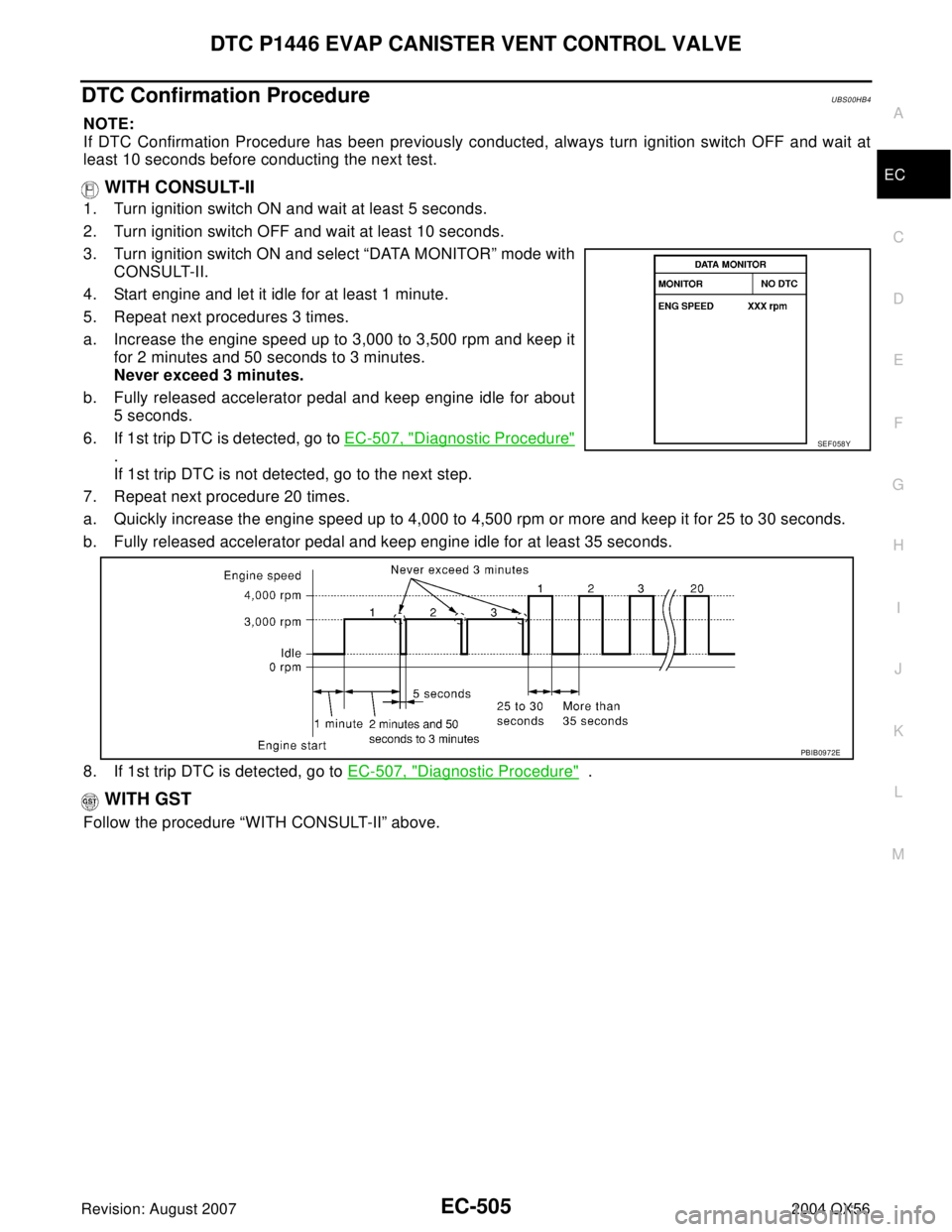
DTC Confirmation ProcedureUBS00HB4
NOTE:
If DTC Confirmation Procedure has been previously conducted, always turn ignition switch OFF and wait at
least 10 seconds before conducting the next test.
WITH CONSULT-II
1. Turn ignition switch ON and wait at least 5 seconds.
2. Turn ignition switch OFF and wait at least 10 seconds.
3. Turn ignition switch ON and select “DATA MONITOR” mode with
CONSULT-II.
4. Start engine and let it idle for at least 1 minute.
5. Repeat next procedures 3 times.
a. Increase the engine speed up to 3,000 to 3,500 rpm and keep it
for 2 minutes and 50 seconds to 3 minutes.
Never exceed 3 minutes.
b. Fully released accelerator pedal and keep engine idle for about
5 seconds.
6. If 1st trip DTC is detected, go to EC-507, "
Diagnostic Procedure"
.
If 1st trip DTC is not detected, go to the next step.
7. Repeat next procedure 20 times.
a. Quickly increase the engine speed up to 4,000 to 4,500 rpm or more and keep it for 25 to 30 seconds.
b. Fully released accelerator pedal and keep engine idle for at least 35 seconds.
8. If 1st trip DTC is detected, go to EC-507, "
Diagnostic Procedure" .
WITH GST
Follow the procedure “WITH CONSULT-II” above.
SEF 0 58 Y
PBIB0972E
Page 1704 of 3371
DTC P1564 ICC STEERING SWITCH
EC-513
C
D
E
F
G
H
I
J
K
L
MA
EC
Revision: August 20072004 QX56
Specification data are reference values and are measured between each terminal and ground.
CAUTION:
Do not use ECM ground terminals when measuring input/output voltage. Doing so may result in dam-
age to the ECM's transistor. Use a ground other than ECM terminals, such as the ground.
TERMI-
NAL
NO.WIRE
COLORITEM CONDITION DATA (DC Voltage)
67 BSensor ground
(ICC steering switch)[Engine is running]
�Warm-up condition
�Idle speedApproximately 0V
99 G/Y ICC steering switch[Ignition switch: ON]
�ICC steering switch: OFFApproximately 4.3V
[Ignition switch: ON]
�ON/OFF (MAIN) switch: PressedApproximately 0V
[Ignition switch: ON]
�CANCEL switch: PressedApproximately 1.3V
[Ignition switch: ON]
�DISTANCE switch: PressedApproximately 2.2V
[Ignition switch: ON]
�COAST/SET switch: PressedApproximately 3V
[Ignition switch: ON]
�ACCEL/RESUME switch: PressedApproximately 3.7V
Page 1711 of 3371
EC-520Revision: August 2007
DTC P1564 ASCD STEERING SWITCH
2004 QX56
Specification data are reference values and are measured between each terminal and ground.
CAUTION:
Do not use ECM ground terminals when measuring input/output voltage. Doing so may result in dam-
age to the ECM's transistor. Use a ground other than ECM terminals, such as the ground.
TER-
MINAL
NO.WIRE
COLORITEM CONDITION DATA (DC Voltage)
67 B Sensor ground[Engine is running]
�Warm-up condition
�Idle speed Approximately 0V
99 G/Y ASCD steering switch[Ignition switch: ON]
�ASCD steering switch: OFF.Approximately 4V
[Ignition switch ON]
�ON/OFF(MAIN) switch: PressedApproximately 0V
[Ignition switch: ON]
�CANCEL switch: PressedApproximately 1V
[Ignition switch: ON]
�COAST/SET switch: PressedApproximately 2V
[Ignition switch: ON]
�ACCEL/RESUME switch: PressedApproximately 3V
Page 1716 of 3371
DTC P1572 ICC BRAKE SWITCH
EC-525
C
D
E
F
G
H
I
J
K
L
MA
EC
Revision: August 20072004 QX56
DTC P1572 ICC BRAKE SWITCHPFP:25320
Component DescriptionUBS00HYZ
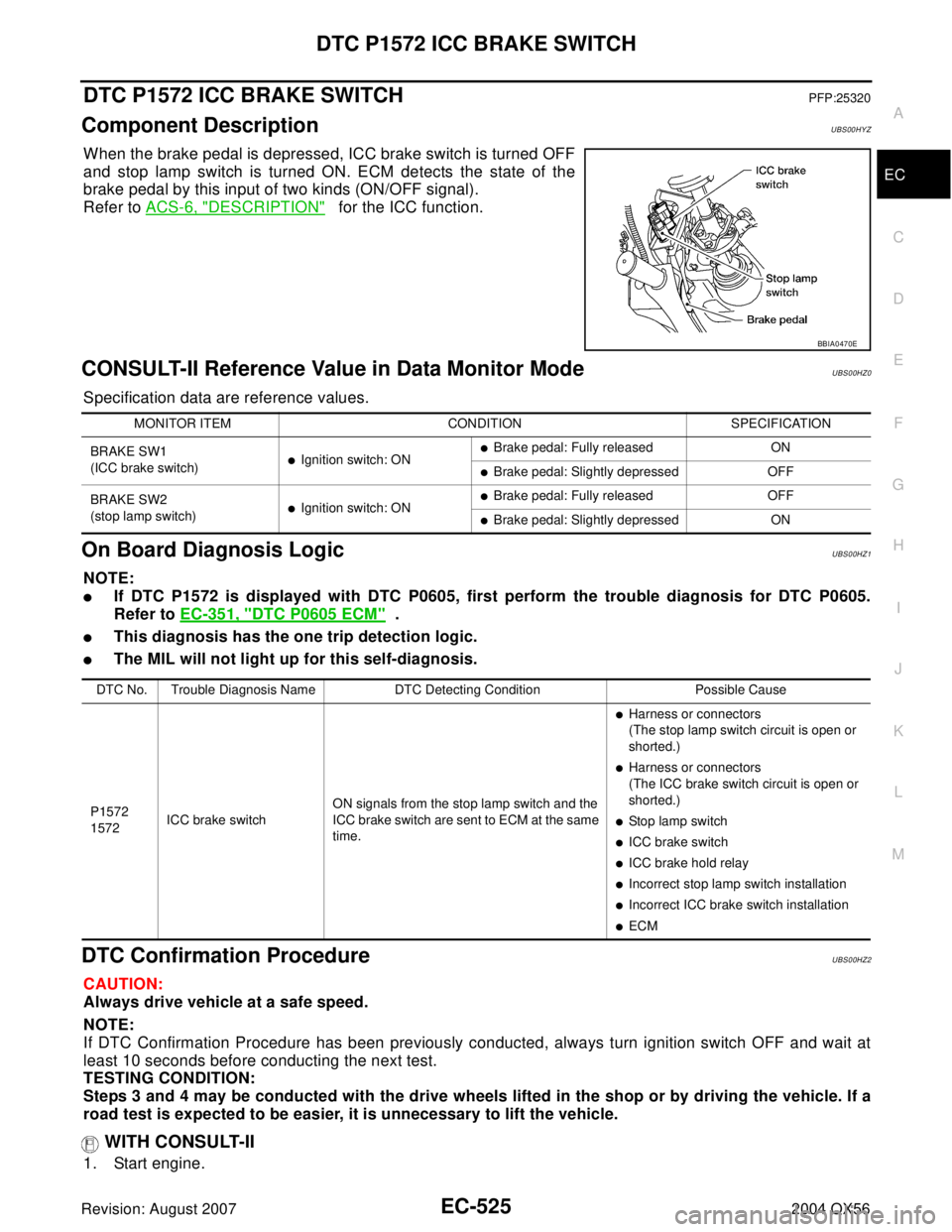
When the brake pedal is depressed, ICC brake switch is turned OFF
and stop lamp switch is turned ON. ECM detects the state of the
brake pedal by this input of two kinds (ON/OFF signal).
Refer to ACS-6, "
DESCRIPTION" for the ICC function.
CONSULT-II Reference Value in Data Monitor ModeUBS00HZ0
Specification data are reference values.
On Board Diagnosis LogicUBS00HZ1
NOTE:
�If DTC P1572 is displayed with DTC P0605, first perform the trouble diagnosis for DTC P0605.
Refer to EC-351, "
DTC P0605 ECM" .
�This diagnosis has the one trip detection logic.
�The MIL will not light up for this self-diagnosis.
DTC Confirmation ProcedureUBS00HZ2
CAUTION:
Always drive vehicle at a safe speed.
NOTE:
If DTC Confirmation Procedure has been previously conducted, always turn ignition switch OFF and wait at
least 10 seconds before conducting the next test.
TESTING CONDITION:
Steps 3 and 4 may be conducted with the drive wheels lifted in the shop or by driving the vehicle. If a
road test is expected to be easier, it is unnecessary to lift the vehicle.
WITH CONSULT-II
1. Start engine.
BBIA0470E
MONITOR ITEM CONDITION SPECIFICATION
BRAKE SW1
(ICC brake switch)
�Ignition switch: ON�Brake pedal: Fully released ON
�Brake pedal: Slightly depressed OFF
BRAKE SW2
(stop lamp switch)
�Ignition switch: ON�Brake pedal: Fully released OFF
�Brake pedal: Slightly depressed ON
DTC No. Trouble Diagnosis Name DTC Detecting Condition Possible Cause
P1572
1572ICC brake switchON signals from the stop lamp switch and the
ICC brake switch are sent to ECM at the same
time.
�Harness or connectors
(The stop lamp switch circuit is open or
shorted.)
�Harness or connectors
(The ICC brake switch circuit is open or
shorted.)
�Stop lamp switch
�ICC brake switch
�ICC brake hold relay
�Incorrect stop lamp switch installation
�Incorrect ICC brake switch installation
�ECM
Page 1726 of 3371
DTC P1572 ASCD BRAKE SWITCH
EC-535
C
D
E
F
G
H
I
J
K
L
MA
EC
Revision: August 20072004 QX56
DTC Confirmation ProcedureUBS00HBI
CAUTION:
Always drive vehicle at a safe speed.
NOTE:
If DTC Confirmation Procedure has been previously conducted, always turn ignition switch OFF and wait at
least 10 seconds before conducting the next test.
TESTING CONDITION:
Steps 3 and 4 may be conducted with the drive wheels lifted in the shop or by driving the vehicle. If a
road test is expected to be easier, it is unnecessary to lift the vehicle.
WITH CONSULT-II
1. Start engine (VDC switch OFF).
2. Select “DATA MONITOR” mode with CONSULT-II.
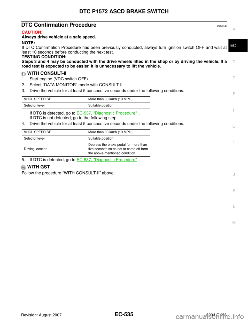
3. Drive the vehicle for at least 5 consecutive seconds under the following conditions.
If DTC is detected, go to EC-537, "
Diagnostic Procedure" .
If DTC is not detected, go to the following step.
4. Drive the vehicle for at least 5 consecutive seconds under the following conditions.
5. If DTC is detected, go to EC-537, "
Diagnostic Procedure" .
WITH GST
Follow the procedure “WITH CONSULT-II” above.
VHCL SPEED SE More than 30 km/h (19 MPH)
Selector lever Suitable position
VHCL SPEED SE More than 30 km/h (19 MPH)
Selector lever Suitable position
Driving locationDepress the brake pedal for more than
five seconds so as not to come off from
the above-mentioned condition.
Page 1733 of 3371
EC-542Revision: August 2007
DTC P1574 ICC VEHICLE SPEED SENSOR
2004 QX56
DTC P1574 ICC VEHICLE SPEED SENSORPFP:31036
Component DescriptionUBS00HZ6
The ECM receives two vehicle speed signals via CAN communication line. One is sent from “unified meter and
A/C amp.”, and the other is from TCM (Transmission control module). The ECM uses these signals for ICC
control. Refer to ACS-6, "
DESCRIPTION" for ICC functions.
On Board Diagnosis LogicUBS00HZ7
�This self-diagnosis has the one trip detection logic.
�The MIL will not light up for this self-diagnosis.
NOTE:
�If DTC P1574 is displayed with DTC U1000, U1001, first perform the trouble diagnosis for DTC
U1000, U1001. Refer to EC-135, "
DTC U1000, U1001 CAN COMMUNICATION LINE" .
�If DTC P1574 is displayed with DTC P0500, first perform the trouble diagnosis for DTC P0500.
Refer to EC-340, "
DTC P0500 VSS" .
�If DTC P1574 is displayed with DTC P0605, first perform the trouble diagnosis for DTC P0605.
Refer to EC-351, "
DTC P0605 ECM" .
DTC Confirmation ProcedureUBS00HZ8
CAUTION:
Always drive vehicle at a safe speed.
NOTE:
If DTC Confirmation Procedure has been previously conducted, always turn ignition switch OFF and wait at
least 10 seconds before conducting the next test.
TESTING CONDITION:
Step 3 may be conducted with the drive wheels lifted in the shop or by driving the vehicle. If a road test
is expected to be easier, it is unnecessary to lift the vehicle.
WITH CONSULT-II
1. Start engine.
2. Select “DATA MONITOR” mode with CONSULT-II.
3. Drive the vehicle at more than 40 km/h (25MPH).
4. If DTC is detected, go to EC-543, "
Diagnostic Procedure" .
WITH GST
Follow the procedure “WITH CONSULT-II” above.
DTC No. Trouble Diagnosis Name DTC Detecting Condition Possible Cause
P1574
1574ICC vehicle speed sensorECM detects a difference between two vehicle
speed signals is out of the specified range.
�Harness or connectors
(The CAN communication line is open or
shorted.)
�Unified meter and A/C amp.
�ABS actuator and electric unit (control unit)
�Wheel sensor
�TCM
�ECM
SEF 0 58 Y