Page 2965 of 3371
SE-16
AUTOMATIC DRIVE POSITIONER
Revision: August 20072004 QX56
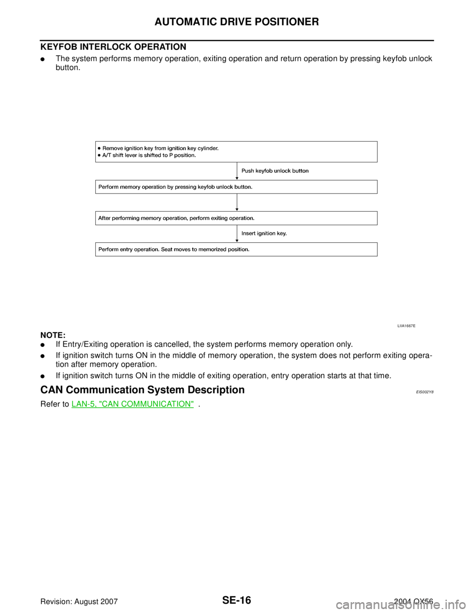
KEYFOB INTERLOCK OPERATION
�The system performs memory operation, exiting operation and return operation by pressing keyfob unlock
button.
NOTE:
�If Entry/Exiting operation is cancelled, the system performs memory operation only.
�If ignition switch turns ON in the middle of memory operation, the system does not perform exiting opera-
tion after memory operation.
�If ignition switch turns ON in the middle of exiting operation, entry operation starts at that time.
CAN Communication System DescriptionEIS002Y8
Refer to LAN-5, "CAN COMMUNICATION" .
LIIA1667E
Page 2990 of 3371

AUTOMATIC DRIVE POSITIONER
SE-41
C
D
E
F
G
H
J
K
L
MA
B
SE
Revision: August 20072004 QX56
ACTIVE TEST
CAUTION:
During vehicle driving, do not perform active test.
NOTE:
If active test is performed, reset seat memory and key fob interlock drive positioner after performing work.
DISPLAY ITEM LIST
CAN Communication Inspection Using CONSULT-II (Self-Diagnosis)EIS002YH
1. SELF-DIAGNOSTIC RESULT CHECK
CAUTION:
If CONSULT-II is used with no connection of CONSULT-II CONVERTER, malfunctions might be
detected in self-diagnosis depending on control unit which carry out CAN communication.
1. Connect to CONSULT-II, and select “AUTO DRIVE POS.” on the “SELECT DIAG SYSTEM” screen.
2. Select “SELF-DIAG RESULTS” on "SELECT DIAG MODE" screen.
3. Check display content in self-diagnostic results.
Contents displayed
No malfunction>>Inspection End.
Malfunction in CAN communication system>>After printing the monitor items, go to “CAN System”. Refer to
LAN-3, "
Precautions When Using CONSULT-II" .
Symptom ChartEIS002YI
MIR/SEN LH U–D “V” Voltage output from LH door mirror sensor (UP/DOWN) is displayed.
PEDAL SEN “V”The pedal position (voltage) judged from the pedal adjust sensor signal is dis-
played. Monitor item [OPERATION or UNIT] Contents
Test item Description
SEAT SLIDE The sliding motor is activated by receiving the drive signal.
SEAT RECLINING The reclining motor is activated by receiving the drive signal.
SEAT LIFTER FR The lifting motor (front) is activated by receiving the drive signal.
SEAT LIFTER RR The lifting motor (rear) is activated by receiving the drive signal.
PEDAL MOTOR The pedal adjust motor is activated by receiving the drive signal.
MEMORY SW INDCTR The memory switch indicator is lit by receiving the drive signal.
MIRROR MOTOR RHThe RH mirror motor moves the mirror UP/DOWN and LEFT/RIGHT by receiving the drive
signal.
MIRROR MOTOR LHThe LH mirror motor moves the mirror UP/DOWN and LEFT/RIGHT by receiving the drive
signal.
CONSULT-II display code Diagnosis item
U1000INITIAL DIAG
TRANSMIT DIAG
BSM
METER/M&A
ECM
SymptomDiagnoses / service procedure Refer to
page
Only setting change function cannot be set with display.1. Preliminary checkSE-34
2. CAN communication inspection using CONSULT-II (self-
diagnosis)SE-41
3. If the above systems are normal, check display systemAV- 6 1
Page 3291 of 3371
WT-12
TROUBLE DIAGNOSES
Revision: August 20072004 QX56
Terminal and Reference Value (BCM)EES0012A
() : Wire colorTerminal
Item ConditionVoltage (V)
(Approx.)
+–
15 (L/W)
GroundTire pressure warning check
connector—5V
18 (P)Remote keyless entry receiver
(Ground)—0V
19 (V/W)Remote keyless entry receiver
(Power supply)Ignition switch OFF
20 (G/W)Remote keyless entry receiver
signal (Signal)Stand-by (keyfob buttons
released)
When remote keyless entry
receiver receives signal from
keyfob (keyfob buttons
pressed)
38 (W/L) Ignition switch Ignition switch ON or START Battery voltage
39 (W) Data line (CAN-H) — —
40 (R) Data line (CAN-L) — —
67 (B) GND — 0V
70 (W/B) Battery power supply — Battery voltage
LIIA1893E
LIIA1894E
LIIA1895E
EES0012A
() : Wire colorTerminal
Item ConditionVoltage (V)
(Approx.)
+–
15 (L/W)
GroundTire pressure warning")