Page 769 of 3371

BL-4
PRECAUTIONS
Revision: August 20072004 QX56
PRECAUTIONSPFP:00001
Precautions for Supplemental Restraint System (SRS) “AIR BAG” and “SEAT
BELT PRE-TENSIONER”
EIS002QW
The Supplemental Restraint System such as “AIR BAG” and “SEAT BELT PRE-TENSIONER”, used along
with a front seat belt, helps to reduce the risk or severity of injury to the driver and front passenger for certain
types of collision. This system includes seat belt switch inputs and dual stage front air bag modules. The SRS
system uses the seat belt switches to determine the front air bag deployment, and may only deploy one front
air bag, depending on the severity of a collision and whether the front occupants are belted or unbelted.
Information necessary to service the system safely is included in the SRS and SB section of this Service Man-
ual.
WAR NIN G:
�To avoid rendering the SRS inoperative, which could increase the risk of personal injury or death
in the event of a collision which would result in air bag inflation, all maintenance must be per-
formed by an authorized NISSAN/INFINITI dealer.
�Improper maintenance, including incorrect removal and installation of the SRS, can lead to per-
sonal injury caused by unintentional activation of the system. For removal of Spiral Cable and Air
Bag Module, see the SRS section.
�Do not use electrical test equipment on any circuit related to the SRS unless instructed to in this
Service Manual. SRS wiring harnesses can be identified by yellow and/or orange harnesses or
harness connectors.
Precautions for workEIS002QX
�After removing and installing the opening/closing parts, be sure to carry out fitting adjustments to check
their operation.
�Check the lubrication level, damage, and wear of each part. If necessary, grease or replace it.
Wiring Diagnosis and Trouble DiagnosisEIS002QY
When you read wiring diagrams, refer to the following:
�GI-15, "How to Read Wiring Diagrams"
�PG-4, "POWER SUPPLY ROUTING CIRCUIT"
When you perform trouble diagnosis, refer to the following:
�GI-11, "HOW TO FOLLOW TEST GROUPS IN TROUBLE DIAGNOSES"
�GI-27, "How to Perform Efficient Diagnosis for an Electrical Incident"
Check for any Service bulletins before servicing the vehicle.
Page 785 of 3371
BL-20
POWER DOOR LOCK SYSTEM
Revision: August 20072004 QX56
Wiring Diagram — D/LOCK —EIS002RB
WIWA0840E
Page 815 of 3371
BL-50
REMOTE KEYLESS ENTRY SYSTEM
Revision: August 20072004 QX56
Wiring Diagram — KEYLES —EIS002RS
LIWA0427E
Page 845 of 3371
BL-80
VEHICLE SECURITY (THEFT WARNING) SYSTEM
Revision: August 20072004 QX56
Wiring Diagram — VEHSEC —EIS002SH
WIWA1075E
Page 873 of 3371
BL-108
AUTOMATIC BACK DOOR SYSTEM
Revision: August 20072004 QX56
Wiring Diagram — B/CLOS —EIS002SX
WIWA0863E
Page 906 of 3371
IVIS (INFINITI VEHICLE IMMOBILIZER SYSTEM-NATS)
BL-141
C
D
E
F
G
H
J
K
L
MA
B
BL
Revision: August 20072004 QX56
Wiring Diagram — NATS —EIS002TP
WIWA1079E
Page 922 of 3371
HOMELINK UNIVERSAL TRANSCEIVER
BL-157
C
D
E
F
G
H
J
K
L
MA
B
BL
Revision: August 20072004 QX56
HOMELINK UNIVERSAL TRANSCEIVERPFP:96401
Wiring Diagram — TRNSCV —EIS002U1
WIWA1080E
Page 1014 of 3371

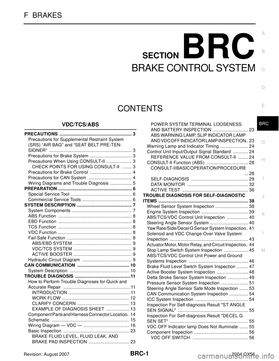
BRC-1
BRAKE CONTROL SYSTEM
F BRAKES
CONTENTS
C
D
E
G
H
I
J
K
L
M
SECTION BRC
A
B
BRC
Revision: August 20072004 QX56VDC/TCS/ABS
PRECAUTIONS .......................................................... 3
Precautions for Supplemental Restraint System
(SRS) “AIR BAG” and “SEAT BELT PRE-TEN-
SIONER” .................................................................. 3
Precautions for Brake System .................................. 3
Precautions When Using CONSULT-II ..................... 3
CHECK POINTS FOR USING CONSULT-II ......... 3
Precautions for Brake Control .................................. 4
Precautions for CAN System ................................... 4
Wiring Diagrams and Trouble Diagnosis .................. 5
PREPARATION ........................................................... 6
Special Service Tool ................................................. 6
Commercial Service Tools ........................................ 6
SYSTEM DESCRIPTION ............................................ 7
System Components ................................................ 7
ABS Function ........................................................... 8
EBD Function ........................................................... 8
TCS Function ........................................................... 8
VDC Function ........................................................... 8
Fail-Safe Function .................................................... 8
ABS/EBD SYSTEM ............................................... 9
VDC/TCS SYSTEM ............................................... 9
ACTIVE BOOSTER ............................................... 9
Hydraulic Circuit Diagram ........................................ 9
CAN COMMUNICATION .......................................... 10
System Description ................................................ 10
TROUBLE DIAGNOSIS .............................................11
How to Perform Trouble Diagnoses for Quick and
Accurate Repair ......................................................11
INTRODUCTION ..................................................11
WORK FLOW ...................................................... 12
CLARIFY CONCERN .......................................... 13
EXAMPLE OF DIAGNOSIS SHEET ................... 13
Component Parts and Harness Connector Location ... 14
Schematic .............................................................. 15
Wiring Diagram — VDC — ..................................... 16
Basic Inspection ..................................................... 23
BRAKE FLUID LEVEL, FLUID LEAK, AND
BRAKE PAD INSPECTION ................................. 23POWER SYSTEM TERMINAL LOOSENESS
AND BATTERY INSPECTION ............................. 23
ABS WARNING LAMP, SLIP INDICATOR LAMP
AND VDC OFF INDICATOR LAMP INSPECTION ... 23
Warning Lamp and Indicator Timing ....................... 24
Control Unit Input/Output Signal Standard ............. 24
REFERENCE VALUE FROM CONSULT-II ......... 24
CONSULT-II Function (ABS) .................................. 28
CONSULT-II BASIC OPERATION PROCEDURE
... 28
SELF-DIAGNOSIS .............................................. 29
DATA MONITOR ................................................. 32
ACTIVE TEST ..................................................... 36
TROUBLE DIAGNOSIS FOR SELF-DIAGNOSTIC
ITEMS ........................................................................ 38
Wheel Sensor System Inspection ........................... 38
Engine System Inspection ...................................... 39
ABS/TCS/VDC Control Unit Inspection .................. 40
Steering Angle Sensor System ............................... 40
Yaw Rate/Side/Decel G Sensor System Inspection ... 41
Solenoid and VDC Change-Over Valve System
Inspection ............................................................... 43
Actuator Motor, Motor Relay, and Circuit Inspection ... 44
Stop Lamp Switch System Inspection .................... 45
ABS/TCS/VDC Control Unit Power and Ground
Systems Inspection ................................................ 46
Brake Fluid Level Switch System Inspection .......... 47
Active Booster System Inspection .......................... 48
Delta Stroke Sensor System Inspection ................. 49
Pressure Sensor System Inspection ...................... 51
Steering Angle Sensor Safe Mode Inspection ........ 53
CAN Communication System Inspection ................ 54
ICC System Inspection ........................................... 54
Inspection For Self-diagnosis Result "ST ANGLE
SEN SIGNAL" ......................................................... 55
Inspection For Self-diagnosis Result "DECEL G
SEN SET" ............................................................... 55
VDC OFF Indicator lamp Does Not Illuminate ........ 55
Component Inspection ............................................ 56
VDC OFF SWITCH ............................................. 56