Page 1598 of 3371
DTC P1148, P1168 CLOSED LOOP CONTROL
EC-407
C
D
E
F
G
H
I
J
K
L
MA
EC
Revision: August 20072004 QX56
DTC P1148, P1168 CLOSED LOOP CONTROLPFP:22690
On Board Diagnosis LogicUBS00H8K
These self-diagnoses have the one trip detection logic.
DTC P1148 or P1168 is displayed with another DTC for air fuel ratio (A/F) sensor 1.
Perform the trouble diagnosis for the corresponding DTC.
DTC No. Trouble diagnosis name DTC detecting condition Possible cause
P1148
11 4 8
(Bank 1)
Closed loop control
functionThe closed loop control function for bank 1
does not operate even when vehicle is driving
in the specified condition.
�Harness or connectors
[The air fuel ratio (A/F) sensor 1 circuit is
open or shorted.]
�Air fuel ratio (A/F) sensor 1
�Air fuel ratio (A/F) sensor 1 heater P1168
11 6 8
(Bank 2)The closed loop control function for bank 2
does not operate even when vehicle is driving
in the specified condition.
Page 1600 of 3371
DTC P1212 TCS COMMUNICATION LINE
EC-409
C
D
E
F
G
H
I
J
K
L
MA
EC
Revision: August 20072004 QX56
DTC P1212 TCS COMMUNICATION LINEPFP:47850
DescriptionUBS00H8P
NOTE:
If DTC P1212 is displayed with DTC U1000 or U1001, first perform the trouble diagnosis for DTC U1000,
U1001. Refer to EC-135, "
DTC U1000, U1001 CAN COMMUNICATION LINE" .
This CAN communication line is used to control the smooth engine operation during the TCS operation. Pulse
signals are exchanged between ECM and “ABS actuator and electric unit (control unit)”.
Be sure to erase the malfunction information such as DTC not only for “ABS actuator and electric unit
(control unit)” but also for ECM after TCS related repair.
On Board Diagnosis LogicUBS00H8Q
Freeze frame data is not stored in the ECM for this self-diagnosis.
The MIL will not light up for this self-diagnosis.
DTC Confirmation ProcedureUBS00H8R
TESTING CONDITION:
Before performing the following procedure, confirm that battery voltage is more than 10.5V at idle.
WITH CONSULT-II
1. Turn ignition switch ON.
2. Select “DATA MONITOR” mode with CONSULT-II.
3. Start engine and let it idle for at least 10 seconds.
4. If a 1st trip DTC is detected, go to EC-409, "
Diagnostic Proce-
dure" .
WITH GST
Follow the procedure “WITH CONSULT-II” above.
Diagnostic ProcedureUBS00H8S
1. CHECK ABS ACTUATOR AND ELECTRIC UNIT (CONTROL UNIT) FUNCTION
Refer to BRC-11, "
TROUBLE DIAGNOSIS" .
>>INSPECTION END
DTC No. Trouble diagnosis name DTC detecting condition Possible cause
P1212
1212TCS communication
lineECM can not receive the information
from “ABS actuator and electric unit (con-
trol unit)” continuously.
�Harness or connectors
(The CAN communication line is open or
shorted.)
�ABS actuator and electric unit (control unit)
�Dead (Weak) battery
SEF 0 58 Y
Page 1601 of 3371
EC-410Revision: August 2007
DTC P1217 ENGINE OVER TEMPERATURE
2004 QX56
DTC P1217 ENGINE OVER TEMPERATUREPFP:00000
DescriptionUBS00H8T
SYSTEM DESCRIPTION
NOTE:
If DTC P1217 is displayed with DTC U1000 or U1001, first perform the trouble diagnosis for DTC U1000,
U1001. Refer to EC-135, "
DTC U1000, U1001 CAN COMMUNICATION LINE" .
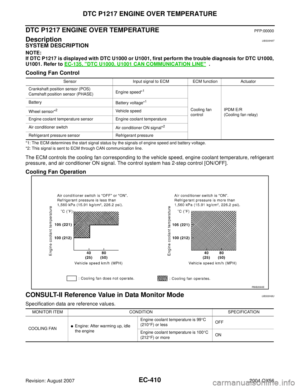
Cooling Fan Control
*1: The ECM determines the start signal status by the signals of engine speed and battery voltage.
*2: This signal is sent to ECM through CAN communication line.
The ECM controls the cooling fan corresponding to the vehicle speed, engine coolant temperature, refrigerant
pressure, and air conditioner ON signal. The control system has 2-step control [ON/OFF].
Cooling Fan Operation
CONSULT-II Reference Value in Data Monitor ModeUBS00H8U
Specification data are reference values.
Sensor Input signal to ECM ECM function Actuator
Crankshaft position sensor (POS)
Camshaft position sensor (PHASE)Engine speed*
1
Cooling fan
controlIPDM E/R
(Cooling fan relay) Battery
Battery voltage*
1
Wheel sensor*2Vehicle speed
Engine coolant temperature sensor Engine coolant temperature
Air conditioner switch
Air conditioner ON signal*
2
Refrigerant pressure sensor Refrigerant pressure
PBIB2060E
MONITOR ITEM CONDITION SPECIFICATION
COOLING FAN
�Engine: After warming up, idle
the engineEngine coolant temperature is 99°C
(210°F) or lessOFF
Engine coolant temperature is 100°C
(212°F) or moreON
Page 1621 of 3371
EC-430Revision: August 2007
DTC P1271, P1281 A/F SENSOR 1
2004 QX56
3. Check “A/F SEN1 (B1)” or “A/F SEN1 (B2)” indication.
If the indication is constantly approx. 0V, go to EC-434, "
Diag-
nostic Procedure" .
If the indication is not constantly approx. 0V, go to next step.
4. Turn ignition switch OFF, wait at least 10 seconds and then
restart engine.
5. Drive and accelerate vehicle to more than 40 km/h (25 MPH)
within 20 seconds after restarting engine.
6. Maintain the following conditions for about 20 consecutive sec-
onds.
NOTE:
�Keep the accelerator pedal as steady as possible during the cruising.
�If this procedure is not completed within 1 minute after restarting engine at step 4, return to step
4.
7. If 1st trip DTC is displayed, go to EC-434, "
Diagnostic Procedure" .
WITH GST
Follow the procedure “WITH CONSULT-II” above.
ENG SPEED 1,000 - 3,200 rpm
VHCL SPEED SE More than 40 km/h (25 MPH)
B/FUEL SCHDL 1.5 - 9.0 msec
Gear position Suitable position
SEF 5 81 Z
Page 1629 of 3371
EC-438Revision: August 2007
DTC P1272, P1282 A/F SENSOR 1
2004 QX56
3. Check “A/F SEN1 (B1)” or “A/F SEN1 (B2)” indication.
If the indication is constantly approx. 5V, go to EC-442, "
Diag-
nostic Procedure" .
If the indication is not constantly approx. 5V, go to next step.
4. Turn ignition switch OFF, wait at least 10 seconds and then
restart engine.
5. Drive and accelerate vehicle to more than 40 km/h (25 MPH)
within 20 seconds after restarting engine.
6. Maintain the following conditions for about 20 consecutive sec-
onds.
NOTE:
�Keep the accelerator pedal as steady as possible during the cruising.
�If this procedure is not completed within 1 minute after restarting engine at step 4, return to step
4.
7. If 1st trip DTC is displayed, go to EC-442, "
Diagnostic Procedure" .
WITH GST
Follow the procedure “WITH CONSULT-II” above.
ENG SPEED 1,000 - 3,200 rpm
VHCL SPEED SE More than 40 km/h (25 MPH)
B/FUEL SCHDL 1.5 - 9.0 msec
Gear position Suitable position
SEF 5 81 Z
Page 1642 of 3371
DTC P1273, P1283 A/F SENSOR 1
EC-451
C
D
E
F
G
H
I
J
K
L
MA
EC
Revision: August 20072004 QX56
3. CLEAR THE SELF-LEARNING DATA
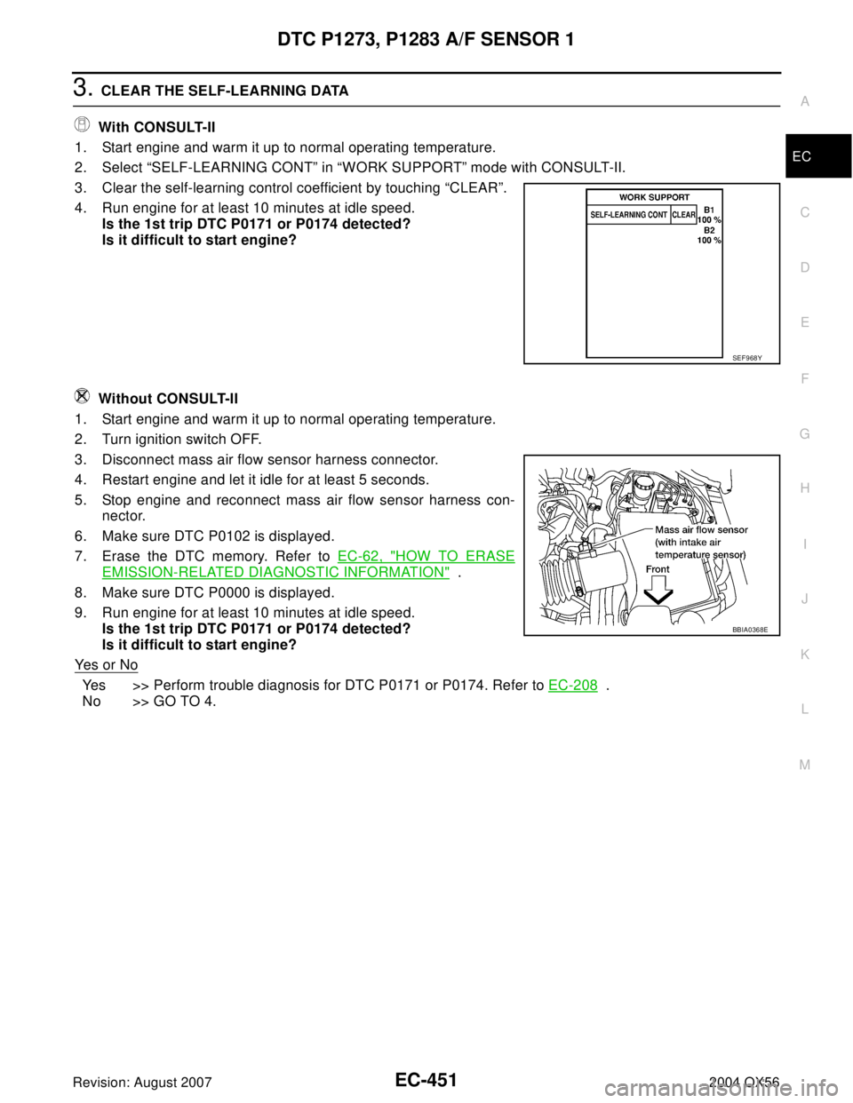
With CONSULT-II
1. Start engine and warm it up to normal operating temperature.
2. Select “SELF-LEARNING CONT” in “WORK SUPPORT” mode with CONSULT-II.
3. Clear the self-learning control coefficient by touching “CLEAR”.
4. Run engine for at least 10 minutes at idle speed.
Is the 1st trip DTC P0171 or P0174 detected?
Is it difficult to start engine?
Without CONSULT-II
1. Start engine and warm it up to normal operating temperature.
2. Turn ignition switch OFF.
3. Disconnect mass air flow sensor harness connector.
4. Restart engine and let it idle for at least 5 seconds.
5. Stop engine and reconnect mass air flow sensor harness con-
nector.
6. Make sure DTC P0102 is displayed.
7. Erase the DTC memory. Refer to EC-62, "
HOW TO ERASE
EMISSION-RELATED DIAGNOSTIC INFORMATION" .
8. Make sure DTC P0000 is displayed.
9. Run engine for at least 10 minutes at idle speed.
Is the 1st trip DTC P0171 or P0174 detected?
Is it difficult to start engine?
Ye s o r N o
Yes >> Perform trouble diagnosis for DTC P0171 or P0174. Refer to EC-208 .
No >> GO TO 4.
SEF 9 68 Y
BBIA0368E
Page 1651 of 3371
EC-460Revision: August 2007
DTC P1274, P1284 A/F SENSOR 1
2004 QX56
3. CLEAR THE SELF-LEARNING DATA.
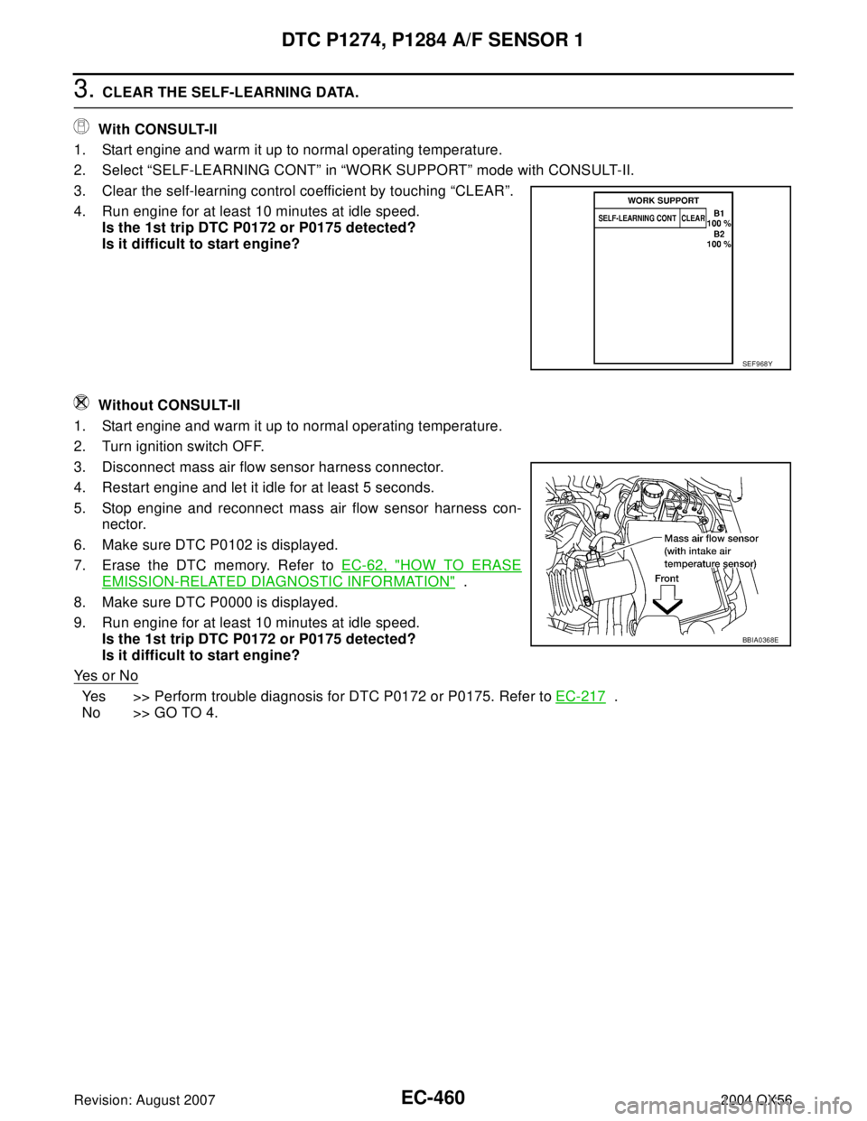
With CONSULT-II
1. Start engine and warm it up to normal operating temperature.
2. Select “SELF-LEARNING CONT” in “WORK SUPPORT” mode with CONSULT-II.
3. Clear the self-learning control coefficient by touching “CLEAR”.
4. Run engine for at least 10 minutes at idle speed.
Is the 1st trip DTC P0172 or P0175 detected?
Is it difficult to start engine?
Without CONSULT-II
1. Start engine and warm it up to normal operating temperature.
2. Turn ignition switch OFF.
3. Disconnect mass air flow sensor harness connector.
4. Restart engine and let it idle for at least 5 seconds.
5. Stop engine and reconnect mass air flow sensor harness con-
nector.
6. Make sure DTC P0102 is displayed.
7. Erase the DTC memory. Refer to EC-62, "
HOW TO ERASE
EMISSION-RELATED DIAGNOSTIC INFORMATION" .
8. Make sure DTC P0000 is displayed.
9. Run engine for at least 10 minutes at idle speed.
Is the 1st trip DTC P0172 or P0175 detected?
Is it difficult to start engine?
Ye s o r N o
Yes >> Perform trouble diagnosis for DTC P0172 or P0175. Refer to EC-217 .
No >> GO TO 4.
SEF 9 68 Y
BBIA0368E
Page 1655 of 3371
EC-464Revision: August 2007
DTC P1276, P1286 A/F SENSOR 1
2004 QX56
If the indication is constantly approx. 1.5V and does not fluctuates, go to EC-469, "Diagnostic Procedure"
.
If the indication fluctuates around 1.5V, go to next step.
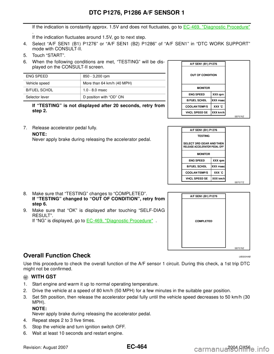
4. Select “A/F SEN1 (B1) P1276” or “A/F SEN1 (B2) P1286” of “A/F SEN1” in “DTC WORK SUPPORT”
mode with CONSULT-II.
5. Touch “START”.
6. When the following conditions are met, “TESTING” will be dis-
played on the CONSULT-II screen.
If “TESTING” is not displayed after 20 seconds, retry from
step 2.
7. Release accelerator pedal fully.
NOTE:
Never apply brake during releasing the accelerator pedal.
8. Make sure that “TESTING” changes to “COMPLETED”.
If “TESTING” changed to “OUT OF CONDITION”, retry from
step 6.
9. Make sure that “OK” is displayed after touching “SELF-DIAG
RESULT”.
If “NG” is displayed, go to EC-469, "
Diagnostic Procedure" .
Overall Function CheckUBS00HAB
Use this procedure to check the overall function of the A/F sensor 1 circuit. During this check, a 1st trip DTC
might not be confirmed.
WITH GST
1. Start engine and warm it up to normal operating temperature.
2. Drive the vehicle at a speed of 80 km/h (50 MPH) for a few minutes in the suitable gear position.
3. Set 5th position, then release the accelerator pedal fully until the vehicle speed decreases to 50 km/h (30
MPH).
NOTE:
Never apply brake during releasing the accelerator pedal.
4. Repeat steps 2 to 3 five times.
5. Stop the vehicle and turn ignition switch OFF.
6. Wait at least 10 seconds and restart engine.
ENG SPEED 850 - 3,200 rpm
Vehicle speed More than 64 km/h (40 MPH)
B/FUEL SCHDL 1.0 - 8.0 msec
Selector lever D position with “OD” ON
SEF 5 76 Z
SEF 5 77 Z
SEF 5 78 Z