Page 2119 of 3371
GI-38
CONSULT-II CHECKING SYSTEM
Revision: August 20072004 QX56
Nickel Metal Hydride Battery Replacement EAS0014S
CONSULT-II contains a nickel metal hydride battery. When replacing the battery obey the following:
WAR NIN G:
Replace the nickel metal hydride battery with Genuine CONSULT-II battery only. Use of another bat-
tery may present a risk of fire or explosion. The battery may present a fire or chemical burn hazard if
mistreated. Do not recharge, disassemble or dispose of in fire.
Keep the battery out of reach of children and discard used battery conforming to the local regulations.
Checking EquipmentEAS0014T
When ordering the below equipment, contact your NISSAN distributor.
CAUTION:
�Previous CONSULT-II “I” and “Y” DLC-I and DLC-II cables should NOT be used anymore because
their DDL connector pins can be damaged during cable swapping.
�If CONSULT-II is used with no connection of CONSULT-II CONVERTER, malfunctions might be
detected in self- diagnosis depending on control unit which carries out CAN communication.
�If CONSULT-II CONVERTER is not connected with CONSULT-II, the vehicle enters “FAIL SAFE
MODE” which will “LIGHT UP the HEAD LIGHT” and /or “COOLING FAN ROTATING” when CON-
SULT-II is started.
NOTE:
�The CONSULT-II must be used in conjunction with a program card.
CONSULT-II does not require loading (Initialization) procedure.
�Be sure the CONSULT-II is turned OFF before installing or removing a program card.
CONSULT-II Start ProcedureEAS0014U
NOTE:
Turning ignition switch off when performing CAN diagnosis could cause CAN memory to be erased.
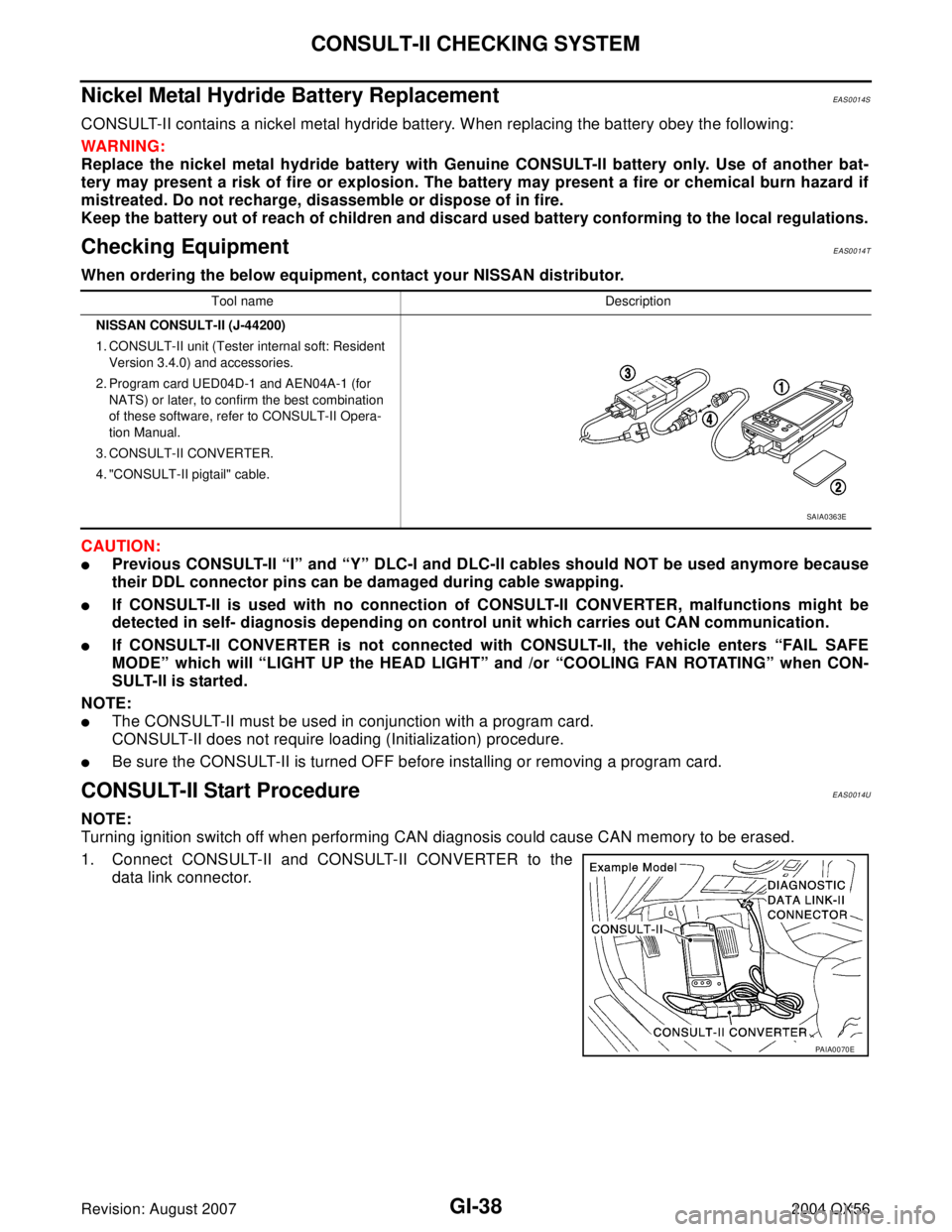
1. Connect CONSULT-II and CONSULT-II CONVERTER to the
data link connector.
Tool name Description
NISSAN CONSULT-II (J-44200)
1. CONSULT-II unit (Tester internal soft: Resident
Version 3.4.0) and accessories.
2. Program card UED04D-1 and AEN04A-1 (for
NATS) or later, to confirm the best combination
of these software, refer to CONSULT-II Opera-
tion Manual.
3. CONSULT-II CONVERTER.
4. "CONSULT-II pigtail" cable.
SAIA0363E
PAIA0070E
Page 2165 of 3371
GW-30
POWER WINDOW SYSTEM
Revision: August 20072004 QX56
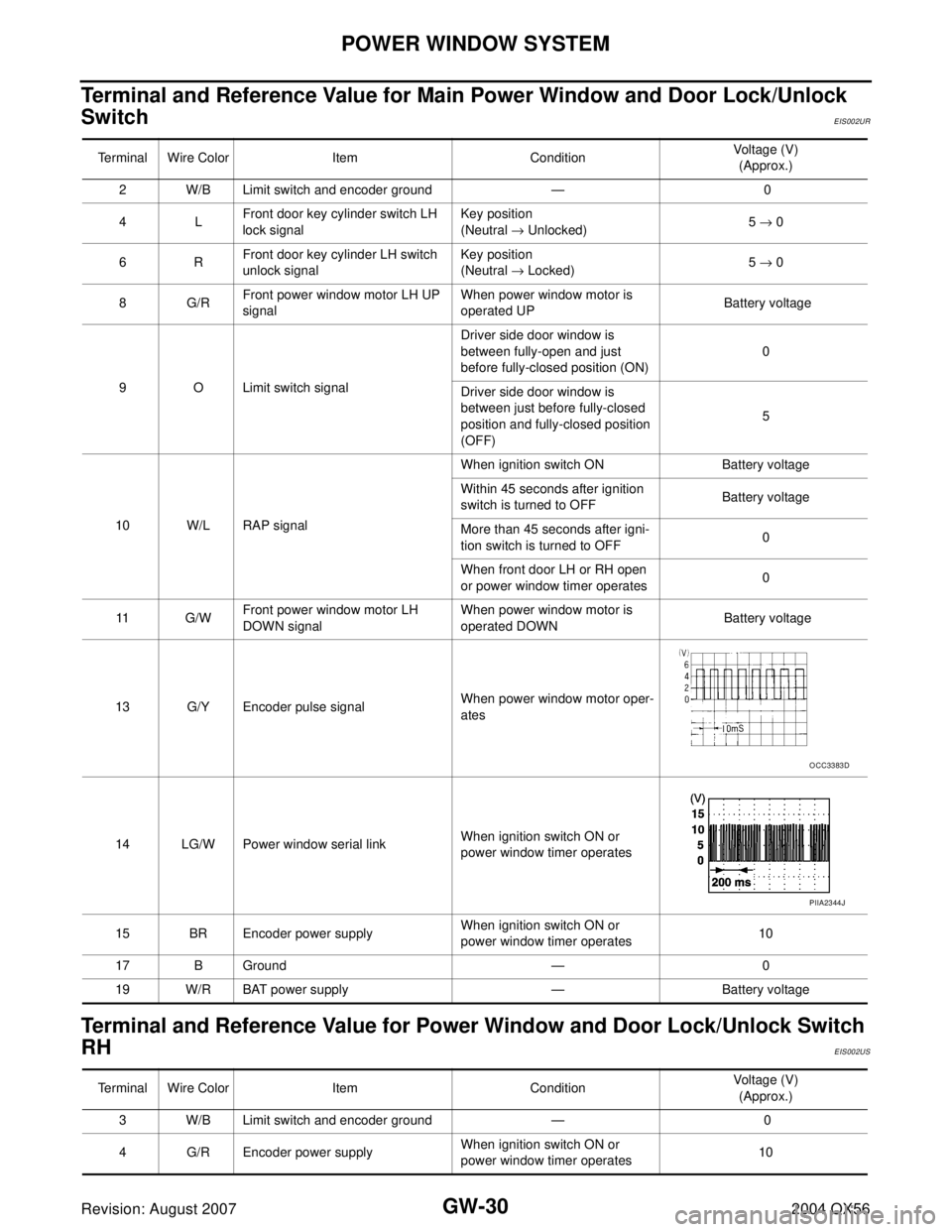
Terminal and Reference Value for Main Power Window and Door Lock/Unlock
Switch
EIS002UR
Terminal and Reference Value for Power Window and Door Lock/Unlock Switch
RH
EIS002US
Terminal Wire Color Item ConditionVoltage (V)
(Approx.)
2 W/B Limit switch and encoder ground — 0
4LFront door key cylinder switch LH
lock signalKey position
(Neutral → Unlocked)5 → 0
6RFront door key cylinder LH switch
unlock signalKey position
(Neutral → Locked)5 → 0
8G/RFront power window motor LH UP
signalWhen power window motor is
operated UP Battery voltage
9 O Limit switch signalDriver side door window is
between fully-open and just
before fully-closed position (ON)0
Driver side door window is
between just before fully-closed
position and fully-closed position
(OFF)5
10 W/L RAP signalWhen ignition switch ON Battery voltage
Within 45 seconds after ignition
switch is turned to OFFBattery voltage
More than 45 seconds after igni-
tion switch is turned to OFF0
When front door LH or RH open
or power window timer operates0
11 G / WFront power window motor LH
DOWN signalWhen power window motor is
operated DOWN Battery voltage
13 G/Y Encoder pulse signalWhen power window motor oper-
ates
14 LG/W Power window serial linkWhen ignition switch ON or
power window timer operates
15 BR Encoder power supplyWhen ignition switch ON or
power window timer operates10
17 B Ground — 0
19 W/R BAT power supply — Battery voltage
OCC3383D
PIIA2344J
Terminal Wire Color Item ConditionVoltage (V)
(Approx.)
3 W/B Limit switch and encoder ground — 0
4 G/R Encoder power supplyWhen ignition switch ON or
power window timer operates10
Page 2166 of 3371
POWER WINDOW SYSTEM
GW-31
C
D
E
F
G
H
J
K
L
MA
B
GW
Revision: August 20072004 QX56
8LFront power window motor RH UP
signalWhen power window motor is
operated UP Battery voltage
9GFront power window motor RH
DOWN signalWhen power window motor is
operated DOWN Battery voltage
10 W/R BAT power supply — Battery voltage
11 B G r o u n d — 0
12 G/Y Encoder pulse signalWhen power window motor oper-
ates
15 G/W Limit switch signalPassenger side door window is
between fully-open and just
before fully-closed position (ON)0
Passenger side door window is
between just before fully-closed
position and fully-closed position
(OFF)5
16 LG/W Power window serial linkWhen ignition switch is ON or
power window timer operating Terminal Wire Color Item ConditionVoltage (V)
(Approx.)
OCC3383D
PIIA2344J
Page 2167 of 3371
GW-32
POWER WINDOW SYSTEM
Revision: August 20072004 QX56
Terminal and Reference Value for BCMEIS002UT
Terminal Wire Color Item ConditionVoltage (V)
(Approx.)
11 O Ignition switch (ACC or ON) Ignition switch
(ACC or ON position)Battery voltage
12 R/L Front door switch RH signalON (Open) Battery voltage
OFF (Close) 0
22 W/V Power window serial linkWhen ignition switch ON or
power window timer operates
38 W/L Ignition switch (ON or START) Ignition switch
(ON or START position)Battery voltage
47 SB Front door switch LH signalON (Open) Battery voltage
OFF (Close) 0
67 B Ground — 0
68 W/L RAP signalWhen ignition switch ON Battery voltage
Within 45 seconds after ignition
switch is turned to OFFBattery voltage
More than 45 seconds after igni-
tion switch is turned to OFF0
When front door LH or RH is
open or power window timer
operates0
69 W/R Power window power supply — Battery voltage
70 W/B BAT power supply — Battery voltage
PIIA2344J
Page 2173 of 3371

GW-38
POWER WINDOW SYSTEM
Revision: August 20072004 QX56
BCM Power Supply and Ground Circuit CheckEIS002UX
1. CHECK FUSE AND FUSIBLE LINK
Check 50A fusible link (letter f located in the fuse and fusible link box).
Check 10A fuse (No. 59, located in the fuse and relay box).
NOTE:
Refer to GW-15, "
Component Parts and Harness Connector Location" .
OK or NG
OK >> GO TO 2.
NG >> If fuse is blown, be sure to eliminate cause of malfunction before installing new fuse. Refer to PG-
3, "PRECAUTIONS" .
2. CHECK POWER SUPPLY CIRCUIT
1. Turn ignition switch ON.
2. Check voltage between BCM connector M18, M20 terminals 11, 38, 70 and ground.
OK or NG
OK >> GO TO 3.
NG >> Repair or replace harness.
3. CHECK GROUND CIRCUIT
1. Turn ignition switch OFF.
2. Disconnect BCM.
3. Check continuity between BCM connector M20 terminal 67 and ground.
OK or NG
OK >> Power supply and ground circuit is OK.
NG >> Repair or replace harness.11 (O) - Ground : Battery voltage
38 (W/L) - Ground : Battery voltage
70 (W/B) - Ground : Battery voltage
WIIA0504E
67 (B) - Ground : Continuity should exist.
LIIA0915E
Page 2174 of 3371
POWER WINDOW SYSTEM
GW-39
C
D
E
F
G
H
J
K
L
MA
B
GW
Revision: August 20072004 QX56
Main Power Window and Door Lock/Unlock Switch Power Supply and Ground
Circuit Check
EIS002UY
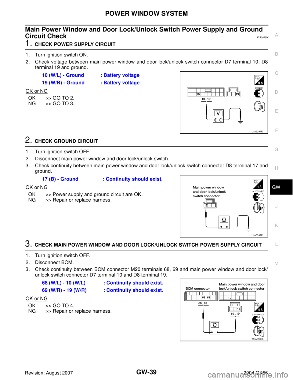
1. CHECK POWER SUPPLY CIRCUIT
1. Turn ignition switch ON.
2. Check voltage between main power window and door lock/unlock switch connector D7 terminal 10, D8
terminal 19 and ground.
OK or NG
OK >> GO TO 2.
NG >> GO TO 3.
2. CHECK GROUND CIRCUIT
1. Turn ignition switch OFF.
2. Disconnect main power window and door lock/unlock switch.
3. Check continuity between main power window and door lock/unlock switch connector D8 terminal 17 and
ground.
OK or NG
OK >> Power supply and ground circuit are OK.
NG >> Repair or replace harness.
3. CHECK MAIN POWER WINDOW AND DOOR LOCK/UNLOCK SWITCH POWER SUPPLY CIRCUIT
1. Turn ignition switch OFF.
2. Disconnect BCM.
3. Check continuity between BCM connector M20 terminals 68, 69 and main power window and door lock/
unlock switch connector D7 terminal 10 and D8 terminal 19.
OK or NG
OK >> GO TO 4.
NG >> Repair or replace harness.10 (W/L) - Ground : Battery voltage
19 (W/R) - Ground : Battery voltage
LIIA2297E
17 (B) - Ground : Continuity should exist.
LIIA0392E
68 (W/L) - 10 (W/L) : Continuity should exist.
69 (W/R) - 19 (W/R) : Continuity should exist.
WIIA0506E
Page 2175 of 3371
GW-40
POWER WINDOW SYSTEM
Revision: August 20072004 QX56
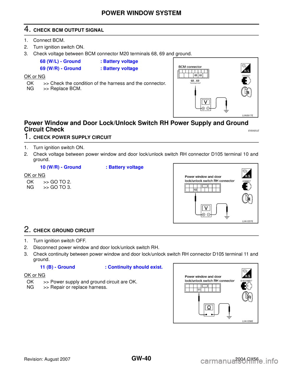
4. CHECK BCM OUTPUT SIGNAL
1. Connect BCM.
2. Turn ignition switch ON.
3. Check voltage between BCM connector M20 terminals 68, 69 and ground.
OK or NG
OK >> Check the condition of the harness and the connector.
NG >> Replace BCM.
Power Window and Door Lock/Unlock Switch RH Power Supply and Ground
Circuit Check
EIS002UZ
1. CHECK POWER SUPPLY CIRCUIT
1. Turn ignition switch ON.
2. Check voltage between power window and door lock/unlock switch RH connector D105 terminal 10 and
ground.
OK or NG
OK >> GO TO 2.
NG >> GO TO 3.
2. CHECK GROUND CIRCUIT
1. Turn ignition switch OFF.
2. Disconnect power window and door lock/unlock switch RH.
3. Check continuity between power window and door lock/unlock switch RH connector D105 terminal 11 and
ground.
OK or NG
OK >> Power supply and ground circuit are OK.
NG >> Repair or replace harness.68 (W/L) - Ground : Battery voltage
69 (W/R) - Ground : Battery voltage
LIIA0917E
10 (W/R) - Ground : Battery voltage
LIIA1257E
11 (B) - Ground : Continuity should exist.
LIIA1258E
Page 2176 of 3371
POWER WINDOW SYSTEM
GW-41
C
D
E
F
G
H
J
K
L
MA
B
GW
Revision: August 20072004 QX56
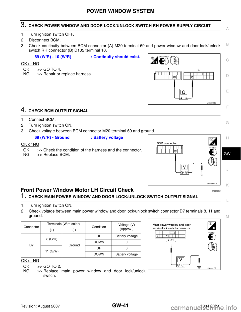
3. CHECK POWER WINDOW AND DOOR LOCK/UNLOCK SWITCH RH POWER SUPPLY CIRCUIT
1. Turn ignition switch OFF.
2. Disconnect BCM.
3. Check continuity between BCM connector (A) M20 terminal 69 and power window and door lock/unlock
switch RH connector (B) D105 terminal 10.
OK or NG
OK >> GO TO 4.
NG >> Repair or replace harness.
4. CHECK BCM OUTPUT SIGNAL
1. Connect BCM.
2. Turn ignition switch ON.
3. Check voltage between BCM connector M20 terminal 69 and ground.
OK or NG
OK >> Check the condition of the harness and the connector.
NG >> Replace BCM.
Front Power Window Motor LH Circuit CheckEIS002V0
1. CHECK MAIN POWER WINDOW AND DOOR LOCK/UNLOCK SWITCH OUTPUT SIGNAL
1. Turn ignition switch ON.
2. Check voltage between main power window and door lock/unlock switch connector D7 terminals 8, 11 and
ground.
OK or NG
OK >> GO TO 2.
NG >> Replace main power window and door lock/unlock
switch. 69 (W/R) - 10 (W/R) : Continuity should exist.
LIIA2298E
69 (W/R) - Ground : Battery voltage
WIIA0508E
ConnectorTerminals (Wire color)
ConditionVoltage (V)
(Approx.)
(+) (-)
D78 (G/R)
GroundUP Battery voltage
DOWN 0
11 (G/W)UP 0
DOWN Battery voltage
LIIA0317E