Page 1816 of 3371
ASCD BRAKE SWITCH
EC-625
C
D
E
F
G
H
I
J
K
L
MA
EC
Revision: August 20072004 QX56
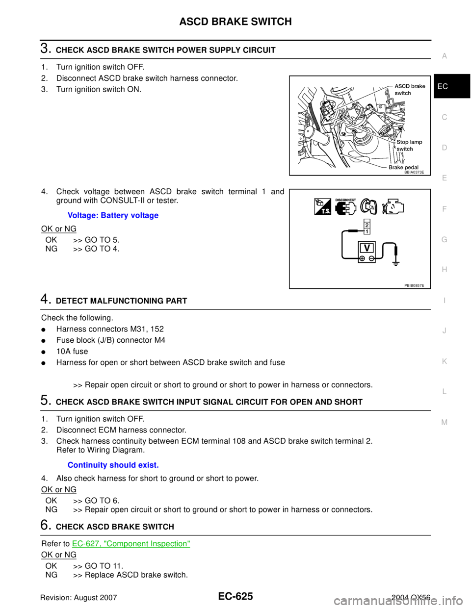
3. CHECK ASCD BRAKE SWITCH POWER SUPPLY CIRCUIT
1. Turn ignition switch OFF.
2. Disconnect ASCD brake switch harness connector.
3. Turn ignition switch ON.
4. Check voltage between ASCD brake switch terminal 1 and
ground with CONSULT-II or tester.
OK or NG
OK >> GO TO 5.
NG >> GO TO 4.
4. DETECT MALFUNCTIONING PART
Check the following.
�Harness connectors M31, 152
�Fuse block (J/B) connector M4
�10A fuse
�Harness for open or short between ASCD brake switch and fuse
>> Repair open circuit or short to ground or short to power in harness or connectors.
5. CHECK ASCD BRAKE SWITCH INPUT SIGNAL CIRCUIT FOR OPEN AND SHORT
1. Turn ignition switch OFF.
2. Disconnect ECM harness connector.
3. Check harness continuity between ECM terminal 108 and ASCD brake switch terminal 2.
Refer to Wiring Diagram.
4. Also check harness for short to ground or short to power.
OK or NG
OK >> GO TO 6.
NG >> Repair open circuit or short to ground or short to power in harness or connectors.
6. CHECK ASCD BRAKE SWITCH
Refer to EC-627, "
Component Inspection"
OK or NG
OK >> GO TO 11.
NG >> Replace ASCD brake switch.
BBIA0373E
Voltage: Battery voltage
PBIB0857E
Continuity should exist.
Page 1817 of 3371
EC-626Revision: August 2007
ASCD BRAKE SWITCH
2004 QX56
7. CHECK STOP LAMP SWITCH POWER SUPPLY CIRCUIT
1. Turn ignition switch OFF.
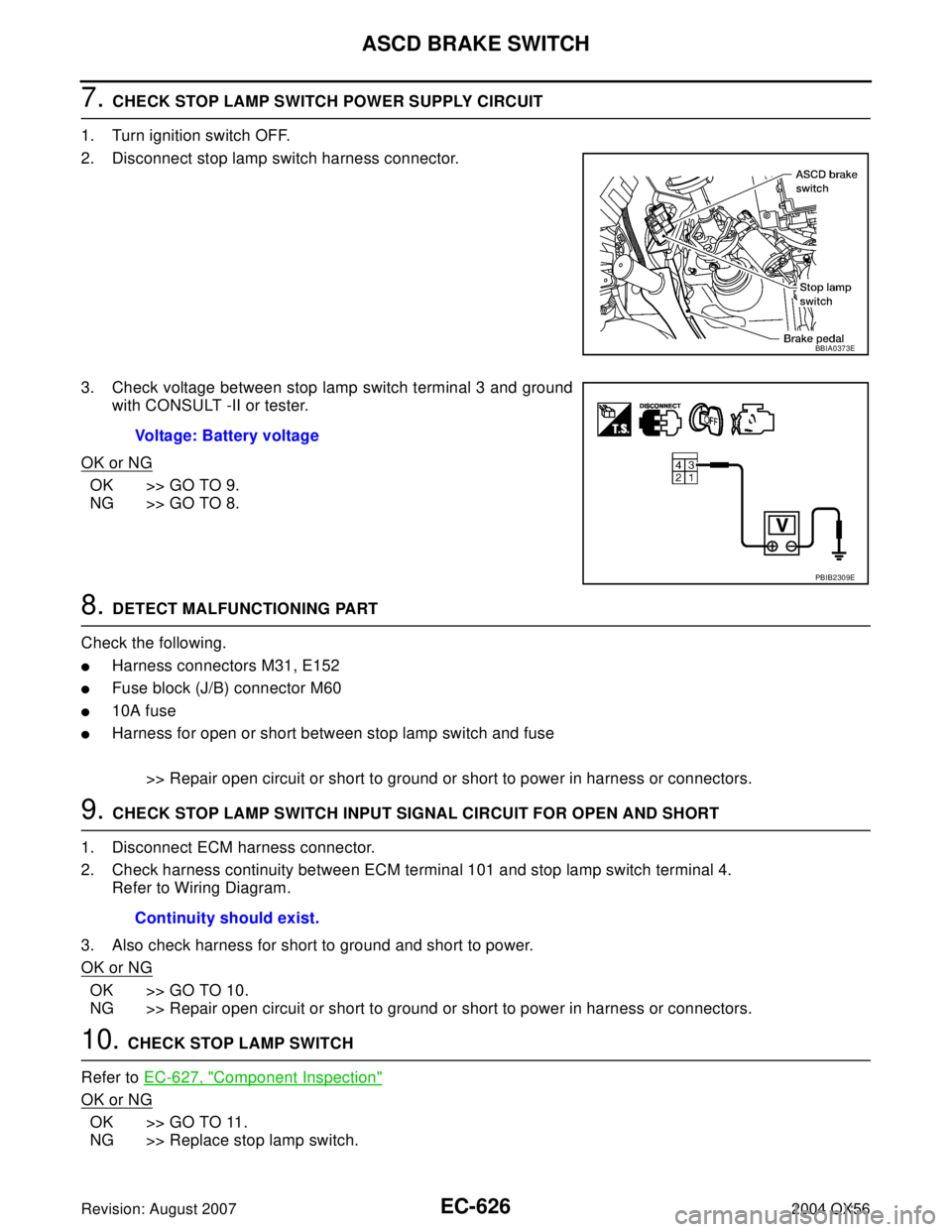
2. Disconnect stop lamp switch harness connector.
3. Check voltage between stop lamp switch terminal 3 and ground
with CONSULT -II or tester.
OK or NG
OK >> GO TO 9.
NG >> GO TO 8.
8. DETECT MALFUNCTIONING PART
Check the following.
�Harness connectors M31, E152
�Fuse block (J/B) connector M60
�10A fuse
�Harness for open or short between stop lamp switch and fuse
>> Repair open circuit or short to ground or short to power in harness or connectors.
9. CHECK STOP LAMP SWITCH INPUT SIGNAL CIRCUIT FOR OPEN AND SHORT
1. Disconnect ECM harness connector.
2. Check harness continuity between ECM terminal 101 and stop lamp switch terminal 4.
Refer to Wiring Diagram.
3. Also check harness for short to ground and short to power.
OK or NG
OK >> GO TO 10.
NG >> Repair open circuit or short to ground or short to power in harness or connectors.
10. CHECK STOP LAMP SWITCH
Refer to EC-627, "
Component Inspection"
OK or NG
OK >> GO TO 11.
NG >> Replace stop lamp switch.
BBIA0373E
Voltage: Battery voltage
PBIB2309E
Continuity should exist.
Page 1830 of 3371
EVAPORATIVE EMISSION SYSTEM
EC-639
C
D
E
F
G
H
I
J
K
L
MA
EC
Revision: August 20072004 QX56
3. Apply battery voltage to between the terminals of EVAP canister vent control valve to make a closed
EVAP system.
4. To locate the leak, deliver positive pressure to the EVAP system until pressure gauge points reach 1.38 to
2.76 kPa (0.014 to 0.028 kg/cm
2 , 0.2 to 0.4 psi).
5. Remove EVAP service port adapter and hose with pressure pump.
6. Locate the leak using a leak detector. Refer to EC-634, "
EVAPORATIVE EMISSION LINE DRAWING" .
BBIA0443E
Page 1831 of 3371
EC-640Revision: August 2007
ON BOARD REFUELING VAPOR RECOVERY (ORVR)
2004 QX56
ON BOARD REFUELING VAPOR RECOVERY (ORVR)PFP:00032
System DescriptionUBS00HE2
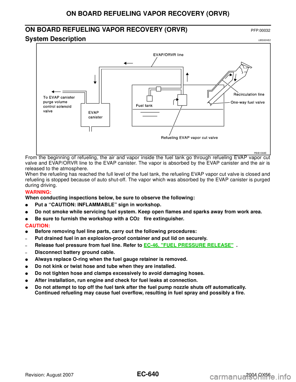
From the beginning of refueling, the air and vapor inside the fuel tank go through refueling EVAP vapor cut
valve and EVAP/ORVR line to the EVAP canister. The vapor is absorbed by the EVAP canister and the air is
released to the atmosphere.
When the refueling has reached the full level of the fuel tank, the refueling EVAP vapor cut valve is closed and
refueling is stopped because of auto shut-off. The vapor which was absorbed by the EVAP canister is purged
during driving.
WAR NIN G:
When conducting inspections below, be sure to observe the following:
�Put a “CAUTION: INFLAMMABLE” sign in workshop.
�Do not smoke while servicing fuel system. Keep open flames and sparks away from work area.
�Be sure to furnish the workshop with a CO2 fire extinguisher.
CAUTION:
�Before removing fuel line parts, carry out the following procedures:
–Put drained fuel in an explosion-proof container and put lid on securely.
–Release fuel pressure from fuel line. Refer to EC-46, "FUEL PRESSURE RELEASE" .
–Disconnect battery ground cable.
�Always replace O-ring when the fuel gauge retainer is removed.
�Do not kink or twist hose and tube when they are installed.
�Do not tighten hose and clamps excessively to avoid damaging hoses.
�After installation, run engine and check for fuel leaks at connection.
�Do not attempt to top off the fuel tank after the fuel pump nozzle shuts off automatically.
Continued refueling may cause fuel overflow, resulting in fuel spray and possibly a fire.
PBIB1068E
Page 1840 of 3371
SERVICE DATA AND SPECIFICATIONS (SDS)
EC-649
C
D
E
F
G
H
I
J
K
L
MA
EC
Revision: August 20072004 QX56
SERVICE DATA AND SPECIFICATIONS (SDS)PFP:00030
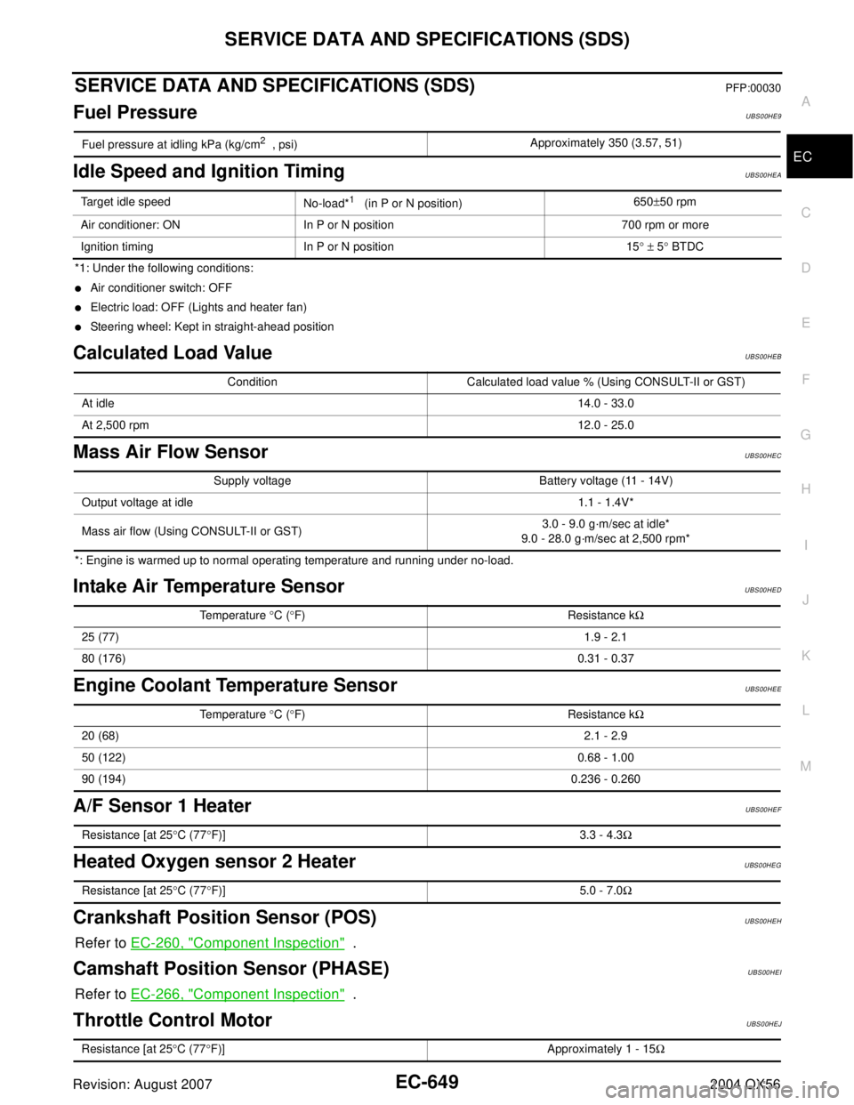
Fuel PressureUBS00HE9
Idle Speed and Ignition TimingUBS00HEA
*1: Under the following conditions:
�Air conditioner switch: OFF
�Electric load: OFF (Lights and heater fan)
�Steering wheel: Kept in straight-ahead position
Calculated Load ValueUBS00HEB
Mass Air Flow SensorUBS00HEC
*: Engine is warmed up to normal operating temperature and running under no-load.
Intake Air Temperature SensorUBS00HED
Engine Coolant Temperature SensorUBS00HEE
A/F Sensor 1 HeaterUBS00HEF
Heated Oxygen sensor 2 HeaterUBS00HEG
Crankshaft Position Sensor (POS)UBS00HEH
Refer to EC-260, "Component Inspection" .
Camshaft Position Sensor (PHASE)UBS00HEI
Refer to EC-266, "Component Inspection" .
Throttle Control MotorUBS00HEJ
Fuel pressure at idling kPa (kg/cm2 , psi)Approximately 350 (3.57, 51)
Target idle speed
No-load*1 (in P or N position)650±50 rpm
Air conditioner: ON In P or N position 700 rpm or more
Ignition timing In P or N position 15° ± 5° BTDC
Condition Calculated load value % (Using CONSULT-II or GST)
At idle14.0 - 33.0
At 2,500 rpm12.0 - 25.0
Supply voltage Battery voltage (11 - 14V)
Output voltage at idle1.1 - 1.4V*
Mass air flow (Using CONSULT-II or GST)3.0 - 9.0 g·m/sec at idle*
9.0 - 28.0 g·m/sec at 2,500 rpm*
Temperature °C (°F) Resistance kΩ
25 (77)1.9 - 2.1
80 (176)0.31 - 0.37
Temperature °C (°F) Resistance kΩ
20 (68)2.1 - 2.9
50 (122)0.68 - 1.00
90 (194)0.236 - 0.260
Resistance [at 25°C (77°F)] 3.3 - 4.3Ω
Resistance [at 25°C (77°F)] 5.0 - 7.0Ω
Resistance [at 25°C (77°F)] Approximately 1 - 15Ω
Page 1879 of 3371
EI-38
HEADLINING
Revision: August 20072004 QX56
CAUTION:
Disconnect both terminals from battery in advance.
1. Remove body side trim. Refer to EI-34, "
BODY SIDE TRIM" .
2. Remove luggage floor trim. Refer to EI-39, "
LUGGAGE FLOOR TRIM" .
3. Remove sunvisor assemblies.
4. Remove sunvisor clips.
5. Remove sunroof welt (if equipped).
6. Remove front roof console.
�Disconnect harnesses.
7. Remove rear roof console.
�Disconnect harnesses.
8. Remove assist grips.
9. Remove lamp assembly from rear roof finisher.
�Disconnect harness.
10. Remove rear roof finisher.
11. Remove headlining.
�Remove clips from rear of headlining.
�Disconnect harnesses.
12. Remove rear air control.
�Disconnect harness.
13. Remove rear audio control assembly.
�Disconnect harness.
14. Remove lamp assemblies.
�Disconnect harnesses.
15. Remove air vents.
16. Remove the front roof console bracket.
17. Remove rear roof console front bracket.
18. Remove assist grip brackets from roof.
Installation is in the reverse order of removal.
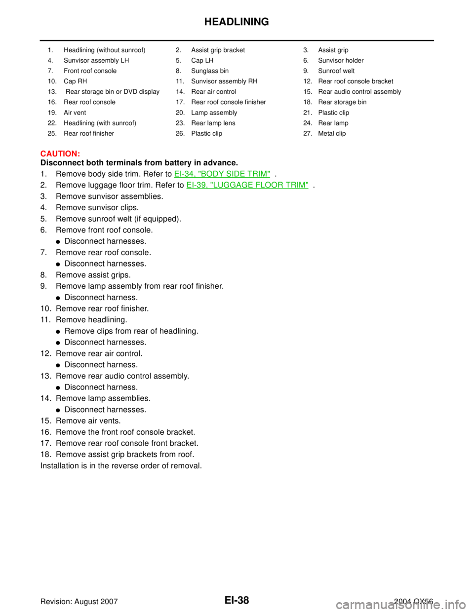
1. Headlining (without sunroof) 2. Assist grip bracket 3. Assist grip
4. Sunvisor assembly LH 5. Cap LH 6. Sunvisor holder
7. Front roof console 8. Sunglass bin 9. Sunroof welt
10. Cap RH 11. Sunvisor assembly RH 12. Rear roof console bracket
13. Rear storage bin or DVD display 14. Rear air control 15. Rear audio control assembly
16. Rear roof console 17. Rear roof console finisher 18. Rear storage bin
19. Air vent 20. Lamp assembly 21. Plastic clip
22. Headlining (with sunroof) 23. Rear lamp lens 24. Rear lamp
25. Rear roof finisher 26. Plastic clip 27. Metal clip
Page 1912 of 3371
FUEL INJECTOR AND FUEL TUBE
EM-29
C
D
E
F
G
H
I
J
K
L
MA
EM
Revision: August 20072004 QX56
FUEL INJECTOR AND FUEL TUBEPFP:16600
Removal and InstallationEBS00ILK
CAUTION:
Do not remove or disassemble parts unless instructed as shown.
REMOVAL
1. Remove the engine room cover using power tool. Refer to EM-11, "REMOVAL" .
2. Release the fuel pressure. Refer to EC-46, "
FUEL PRESSURE RELEASE" .
3. Disconnect the negative battery terminal.
4. Disconnect the fuel injector harness connectors.
5. Disconnect the fuel hose assembly from the fuel tubes (right bank and left bank).
CAUTION:
�Plug the fuel hoses to prevent fuel from draining.
�Do not separate the fuel connector and fuel hose.
6. Remove the fuel injectors with the fuel tube assembly.
1. Fuel tube (right bank) 2. Cap 3. Fuel damper
4. O-ring 5. O-ring (Blue) 6. Fuel injector
7. Clip 8. O-ring (Brown) 9. O-ring
10. Fuel hose assembly 11. Fuel tube (left bank)
KBIA2472E
Page 1935 of 3371
EM-52Revision: August 2007
CAMSHAFT
2004 QX56
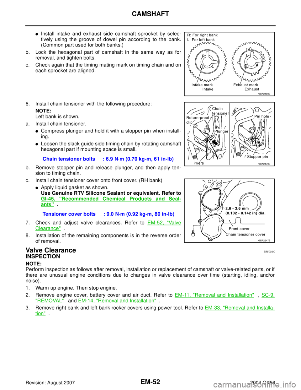
�Install intake and exhaust side camshaft sprocket by selec-
tively using the groove of dowel pin according to the bank.
(Common part used for both banks.)
b. Lock the hexagonal part of camshaft in the same way as for
removal, and tighten bolts.
c. Check again that the timing mating mark on timing chain and on
each sprocket are aligned.
6. Install chain tensioner with the following procedure:
NOTE:
Left bank is shown.
a. Install chain tensioner.
�Compress plunger and hold it with a stopper pin when install-
ing.
�Loosen the slack guide side timing chain by rotating camshaft
hexagonal part if mounting space is small.
b. Remove stopper pin and release plunger, and then apply ten-
sion to timing chain.
c. Install chain tensioner cover onto front cover. (RH bank)
�Apply liquid gasket as shown.
Use Genuine RTV Silicone Sealant or equivalent. Refer to
GI-45, "
Recommended Chemical Products and Seal-
ants" .
7. Check and adjust valve clearances. Refer to EM-52, "
Va l v e
Clearance" .
8. Installation of the remaining components is in the reverse order
of removal.
Va lv e C le a ra n c eEBS00ILO
INSPECTION
NOTE:
Perform inspection as follows after removal, installation or replacement of camshaft or valve-related parts, or if
there are unusual engine conditions due to changes in valve clearance over time (starting, idling, and/or
noise).
1. Warm up engine. Then stop engine.
2. Remove engine cover, battery cover and air duct. Refer to EM-11, "
Removal and Installation" , SC-9,
"REMOVAL" and EM-14, "Removal and Installation" .
3. Remove right bank and left bank rocker covers using power tool. Refer to EM-33, "
Removal and Installa-
tion" .
KBIA2480E
Chain tensioner bolts : 6.9 N·m (0.70 kg-m, 61 in-lb)
Tensioner cover bolts : 9.0 N·m (0.92 kg-m, 80 in-lb)KBIA2479E
KBIA2547E