2004 INFINITI QX56 ECO mode
[x] Cancel search: ECO modePage 3138 of 3371

ALL-MODE 4WD SYSTEM
TF-13
C
E
F
G
H
I
J
K
L
MA
B
TF
Revision: August 20072004 QX56
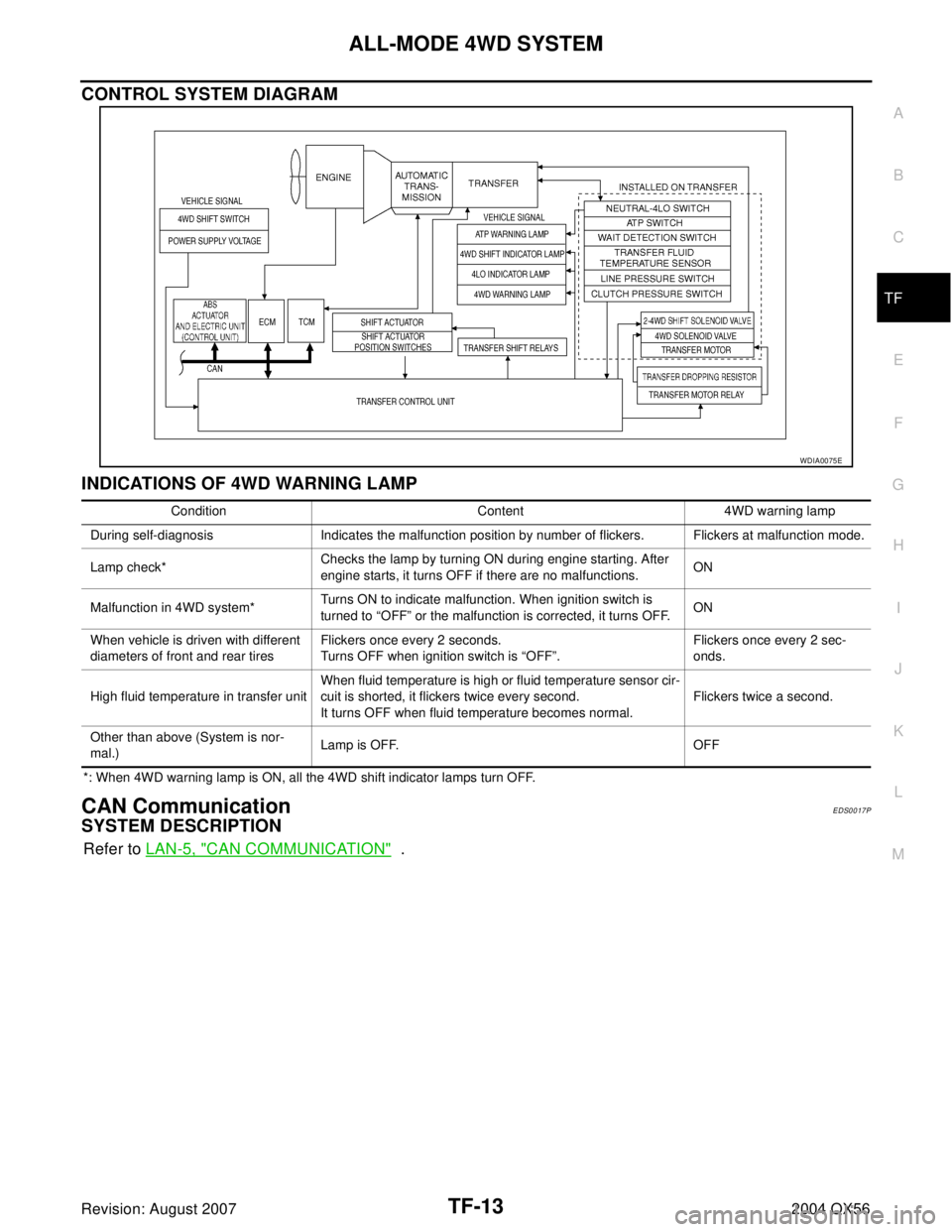
CONTROL SYSTEM DIAGRAM
INDICATIONS OF 4WD WARNING LAMP
*: When 4WD warning lamp is ON, all the 4WD shift indicator lamps turn OFF.
CAN CommunicationEDS0017P
SYSTEM DESCRIPTION
Refer to LAN-5, "CAN COMMUNICATION" .
WDIA0075E
Condition Content 4WD warning lamp
During self-diagnosis Indicates the malfunction position by number of flickers. Flickers at malfunction mode.
Lamp check*Checks the lamp by turning ON during engine starting. After
engine starts, it turns OFF if there are no malfunctions.ON
Malfunction in 4WD system*Turns ON to indicate malfunction. When ignition switch is
turned to “OFF” or the malfunction is corrected, it turns OFF.ON
When vehicle is driven with different
diameters of front and rear tiresFlickers once every 2 seconds.
Turns OFF when ignition switch is “OFF”.Flickers once every 2 sec-
onds.
High fluid temperature in transfer unitWhen fluid temperature is high or fluid temperature sensor cir-
cuit is shorted, it flickers twice every second.
It turns OFF when fluid temperature becomes normal.Flickers twice a second.
Other than above (System is nor-
mal.)Lamp is OFF. OFF
Page 3140 of 3371

ALL-MODE 4WD SYSTEM
TF-15
C
E
F
G
H
I
J
K
L
MA
B
TF
Revision: August 20072004 QX56
Description of Electrical PartsEDS0017R
TRANSFER MOTOR
1. The transfer motor drives the sub-oil pump to provide proper lubrication and oil pressure control when the
vehicle is at standstill, during low-speed operations or is being driven in reverse.
2. The main oil pump is operated by the driving force of the mainshaft. In other words, sufficient oil pressure
buildup does not occur when the vehicle is at standstill or during low-speed operations. While the vehicle
is being driven in reverse, the main oil pump rotates in the reverse direction. Therefore the main oil pump
does not discharge oil pressure. During any of the above vehicle operations, the transfer motor drives the
sub-oil pump to compensate for insufficient oil pressure.
3. The transfer motor operates as follows:
1. The motor relay turns OFF in the 2WD mode.
2. The motor relay operates as described in the table below in modes other than the 2WD mode.
Ta b l e 1
Ta b l e 2
NOTE:
OFF (after 2.5 seconds have elapsed.)
4. 4WD shift switch, PNP switch, Neutral-4LO switch, vehicle speed sensor and throttle position sensor are
used in conjunction with the transfer motor.
WAIT DETECTION SWITCH
1. The wait detection switch releases the “booming” torque produced in the propeller shaft. After the release
of the “booming” torque, the wait detection switch helps provide the 4WD lock gear (clutch drum) shifts. A
difference may occur between the operation (“4LO” to “4H” shift only) of the 4WD shift switch and actual
drive mode. At this point, the wait detection switch senses an actual drive mode.
2. The wait detection switch operates as follows:
4WD lock gear (clutch drum) locked: ON
4WD lock gear (clutch drum) released: OFF
3. The wait detection switch senses an actual drive mode and the 4WD shift indicator lamp indicates the
vehicle drive mode.
2-4WD SHIFT SOLENOID VALVE
The 2-4WD shift solenoid valve operates to apply oil pressure to the wet, multiplate clutch, depending on the
drive mode. The driving force is transmitted to the front wheels through the clutch when the vehicle is set in the
4WD mode. Setting the vehicle in the 2WD mode requires no pressure buildup. In other words, pressure force
applied to the wet, multiplate clutch becomes zero.
PNP switch “R” position VFF (Vehicle speed) A/T position Motor relay drive command
ON — R ON
OFF0Positions other than the “P” or
“N” positionsON
—“P” or “N” position (See Table
2.)—
0 < VFF ≤ 50 km/h (31 MPH) — ON
50 km/h (31 MPH) < VFF < 55
km/h (34 MPH)—HOLD
55 km/h (34 MPH) ≤ VFF — OFF
A/T position N-4L SW 4WD modeThrottle position
0 - 0.07/8 0.07/8 - 1/8 1/8 - MAX
NOFFLOCK (4H) ON ON ON
Positions other than
the LOCK position
(2WD or AUTO)See NOTE. HOLD ON
ON — See NOTE. HOLD ON
P——See NOTE.HOLDON
Page 3161 of 3371
![INFINITI QX56 2004 Factory Service Manual TF-36
ON BOARD DIAGNOSTIC SYSTEM DESCRIPTION
Revision: August 20072004 QX56
N position switch TF [ON-OFF] N position switch of transfer
Line pressure switch [ON-OFF] Line pressure switch
Clutch pressu INFINITI QX56 2004 Factory Service Manual TF-36
ON BOARD DIAGNOSTIC SYSTEM DESCRIPTION
Revision: August 20072004 QX56
N position switch TF [ON-OFF] N position switch of transfer
Line pressure switch [ON-OFF] Line pressure switch
Clutch pressu](/manual-img/42/57034/w960_57034-3160.png)
TF-36
ON BOARD DIAGNOSTIC SYSTEM DESCRIPTION
Revision: August 20072004 QX56
N position switch TF [ON-OFF] N position switch of transfer
Line pressure switch [ON-OFF] Line pressure switch
Clutch pressure switch [ON-OFF] Clutch pressure switch
ATP switch [ON-OFF]—
N position switch AT [ON-OFF] “N” position on A/T PNP switch
R position switch AT [ON-OFF] “R” position on A/T PNP switch
P position switch AT [ON-OFF] “P” position on A/T PNP switch
ABS operation switch [ON-OFF] ABS operation switch
Wait detection switch [ON-OFF] —
Throttle positionThrottle opening recognized by transfer
control unit
4WD-mode4WD-mode recognized by transfer control
unit (2WD, AUTO, 4H & 4LO)
Vehicle speed comp [km/h (MPH)]Vehicle speed recognized by transfer con-
trol unit
*Control torque [N·m (kg-m, ft.-lb.)]Calculated torque recognized by transfer
control unit
Duty solenoid valve [%]
(Transfer 4WD solenoid valve)—
2-4WD shift solenoid valve [ON-
OFF]
Control signal outputs of transfer control
unit Transfer motor relay [ON-OFF]
Shift activating 1 [ON-OFF]
Shift activating 2 [ON-OFF]
2-4WD shift solenoid valve monitor
[ON-OFF]
Check signal (re-input signal) of transfer
control unit control signal output is dis-
played. If circuit is shorted or open, ON/OFF
state does not change. Transfer motor relay monitor [ON-
OFF]
Shift activating monitor 1 [ON-OFF]
Shift activating monitor 2 [ON-OFF]
4WD fail lamp [ON-OFF]Transfer control unit control signal output for
4WD warning lamp (left)
Shift position switch 1 [ON-OFF] —
Shift position switch 2 [ON-OFF] —
2WD indicator lamp [ON-OFF]Transfer control unit control signal output for
4WD shift indicator lamp (rear)
AUTO indicator lamp [ON-OFF]Transfer control unit control signal output for
4WD shift indicator lamp (front & rear)
LOCK indicator lamp [ON-OFF]Transfer control unit control signal output for
4WD shift indicator lamp (center)
4LO indicator lamp [ON-OFF]Transfer control unit control signal output for
4WD shift indicator lamp (right) Item [Unit]Monitor item
Remarks ECU
INPUT
SIGNALSMAIN
SIGNALSSELEC-
TION
FROM
MENU
Page 3165 of 3371

TF-40
ON BOARD DIAGNOSTIC SYSTEM DESCRIPTION
Revision: August 20072004 QX56
4WD-mode2WD
4WD shift
switchIn “2WD” position
AUTO In “AUTO” position
LOCK In “4H” position
4L In “4LO” position
Front wheel speed
(VHCL/S SEN-FR)0 - 255 km/h (0 - 158 MPH) 0 km/h (vehicle at standstill)
Rear wheel speed
(VHCL/S SEN-RR)0 - 255 km/h (0 - 158 MPH) 0 km/h (vehicle at standstill)
Shift ACTR operating 1
(SHIFT ACT 1)
Shift activating monitor 1
(SHIFT AC MON 1)OFF During normal operation
ON During shifts from “4H” to “4LO” position
Shift ACTR operating 2
(SHIFT ACT 2)
Shift activating monitor 2
(SHIFT AC MON 2)OFF During normal operation
ON During shifts from “4LO” to “4H” position
4WD fail lampOFF During normal operation
ONDuring 2-second period (after key switch turned to “ON”)
or when system is out of order
Shift ACTR position sensing switch 1
(SHIFT POS SW 1)OFF 4WD shift switch is in a position other than “4LO”.
ON 4WD shift switch in “4LO” position
Shift ACTR position sensing switch 2
(SHIFT POS SW 2)OFF 4WD shift switch in “4LO” position
ON 4WD shift switch is in a position other than “4LO”.
2WD indicator lamp
(2WD IND)OFF Engine at rest or system out of order
ON Except the above condition Indicated items
(Screen terms for CONSULT-II, “DATA
MONITOR” mode)Display Conditions
Page 3292 of 3371

TROUBLE DIAGNOSES
WT-13
C
D
F
G
H
I
J
K
L
MA
B
WT
Revision: August 20072004 QX56
ID Registration ProcedureEES0012B
ID REGISTRATION WITH TRANSMITTER ACTIVATION TOOL
NOTE:
This procedure must be done after replacement of a low tire pressure warning transmitter or BCM.
New replacement transmitters are provided "asleep" and must first be "woken up" using Transmitter
Activation Tool J-45295 before ID registration can be performed.
CAUTION:
If CONSULT-II is used with no connection of CONSULT-II CONVERTER, malfunction might be detected
during self-diagnosis depending on control unit which carries out CAN communication.
1. With the ignition switch OFF, connect CONSULT-II and CONSULT-II CONVERTER to the data link con-
nector, then turn the ignition switch ON.
2. Select "START (NISSAN BASED VHCL)".
3. Touch “BCM” on "SELECT SYSTEM" screen.
NOTE:
If "BCM" is not indicated, go to LAN-5, "
CAN COMMUNICATION" .
4. Select “AIR PRESSURE MONITOR” on "SELECT TEST ITEM" screen.
5. Select “WORK SUPPORT” on "SELECT DIAG MODE" screen, and select "ID REGIST".
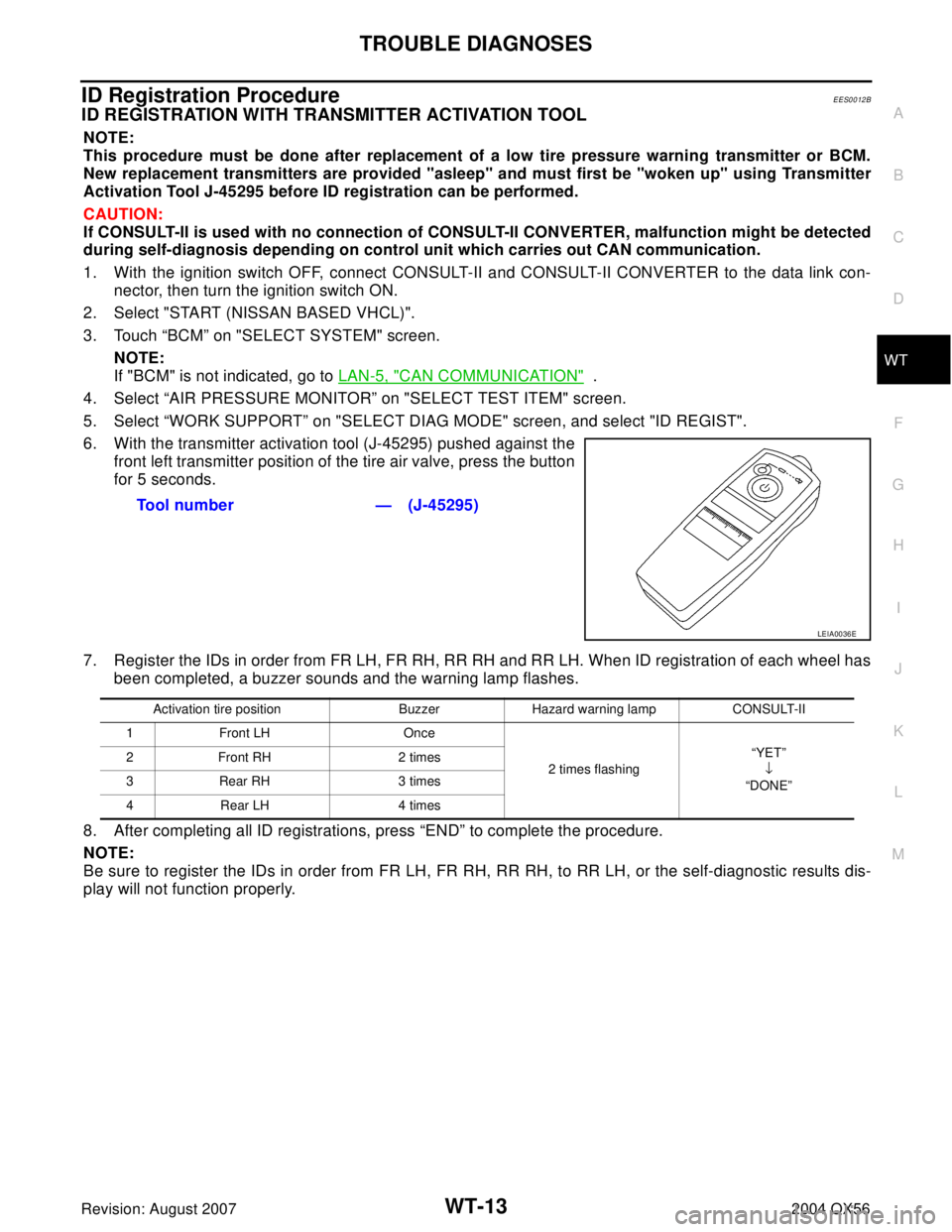
6. With the transmitter activation tool (J-45295) pushed against the
front left transmitter position of the tire air valve, press the button
for 5 seconds.
7. Register the IDs in order from FR LH, FR RH, RR RH and RR LH. When ID registration of each wheel has
been completed, a buzzer sounds and the warning lamp flashes.
8. After completing all ID registrations, press “END” to complete the procedure.
NOTE:
Be sure to register the IDs in order from FR LH, FR RH, RR RH, to RR LH, or the self-diagnostic results dis-
play will not function properly.Tool number — (J-45295)
LEIA0036E
Activation tire position Buzzer Hazard warning lamp CONSULT-II
1Front LH Once
2 times flashing“YET”
↓
“DONE” 2 Front RH 2 times
3 Rear RH 3 times
4 Rear LH 4 times
Page 3296 of 3371

TROUBLE DIAGNOSES
WT-17
C
D
F
G
H
I
J
K
L
MA
B
WT
Revision: August 20072004 QX56
Self-DiagnosisEES0012D
DESCRIPTION
During driving, the low tire pressure warning system receives the signal transmitted from the transmitter
installed in each wheel, and gives alarms when the tire pressure becomes low. The control unit (BCM) for this
system has pressure judgement and trouble diagnosis functions.
FUNCTION
When the low tire pressure warning system detects low inflation pressure or another unusual symptom, the
warning lamp in the combination meter comes on. To start the self-diagnostic results mode, ground the tire
pressure warning check terminal. The malfunction location is indicated by the low tire pressure warning lamp
flashing and the buzzer sounding.
CONSULT-II
CONSULT-II Application to Low Tire Pressure Warning System
× : Applicable
– : Not applicable
Self-Diagnostic Results Mode
NOTE:
Before performing the self-diagnosis, be sure to register the ID or the actual malfunction location may be different from that displayed on
CONSULT-II.ITEM SELF-DIAGNOSTIC RESULTS DATA MONITOR
Front - Left transmitter××
Front - Right transmitter××
Rear - Left transmitter××
Rear - Right transmitter××
Low tire pressure warning lamp —×
Vehicle speed××
Buzzer (in combination meter) —×
CAN Communication××
Diagnostic item Diagnostic item is detected when ···
FLAT - TIRE - FL
FLAT - TIRE - FR
FLAT - TIRE - RR
FLAT - TIRE - RLFront-left tire pressure drops to 193 kPa (2.0 kg/cm
2 , 28 psi) or less
Front-right tire pressure drops to 193 kPa (2.0 kg/cm2 , 28 psi) or less
Rear-right tire pressure drops to 193 kPa (2.0 kg/cm2 , 28 psi) or less
Rear-left tire pressure drops to 193 kPa (2.0 kg/cm2 , 28 psi) or less
[NO-DATA] - FL
[NO-DATA] - FR
[NO-DATA] - RR
[NO-DATA] - RLData from front-left transmitter cannot be received.
Data from front-right transmitter cannot be received.
Data from rear-right transmitter cannot be received.
Data from rear-left transmitter cannot be received.
[CHECKSUM- ERR] - FL
[CHECKSUM- ERR] - FR
[CHECKSUM- ERR] - RR
[CHECKSUM- ERR] - RLChecksum data from front-left transmitter is malfunctioning.
Checksum data from front-right transmitter is malfunctioning.
Checksum data from rear-right transmitter is malfunctioning.
Checksum data from rear-left transmitter is malfunctioning.
[PRESSDATA- ERR] - FL
[PRESSDATA- ERR] - FR
[PRESSDATA- ERR] - RR
[PRESSDATA- ERR] - RLAir pressure data from front-left transmitter is malfunctioning.
Air pressure data from front-right transmitter is malfunctioning.
Air pressure data from rear-right transmitter is malfunctioning.
Air pressure data from rear-left transmitter is malfunctioning.
[CODE- ERR] - FL
[CODE- ERR] - FR
[CODE- ERR] - RR
[CODE- ERR] - RLFunction code data from front-left transmitter is malfunctioning.
Function code data from front-right transmitter is malfunctioning.
Function code data from rear-right transmitter is malfunctioning.
Function code data from rear-left transmitter is malfunctioning.
[BATT - VOLT - LOW] - FL
[BATT - VOLT - LOW] - FR
[BATT - VOLT - LOW] - RR
[BATT - VOLT - LOW] - RLBattery voltage of front-left transmitter drops.
Battery voltage of front-right transmitter drops.
Battery voltage of rear-right transmitter drops.
Battery voltage of rear-left transmitter drops.
VHCL_SPEED_SIG_ERR Vehicle speed signal is in error.
Page 3329 of 3371

WW-16
FRONT WIPER AND WASHER SYSTEM
Revision: August 20072004 QX56
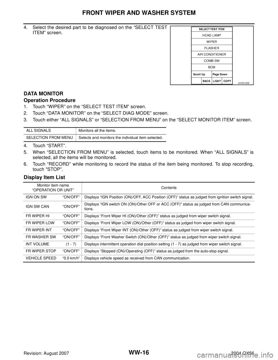
4. Select the desired part to be diagnosed on the “SELECT TEST
ITEM” screen.
DATA MONITOR
Operation Procedure
1. Touch “WIPER” on the “SELECT TEST ITEM” screen.
2. Touch “DATA MONITOR” on the “SELECT DIAG MODE” screen.
3. Touch either “ALL SIGNALS” or “SELECTION FROM MENU” on the “SELECT MONITOR ITEM” screen.
4. Touch “START”.
5. When “SELECTION FROM MENU” is selected, touch items to be monitored. When “ALL SIGNALS” is
selected, all the items will be monitored.
6. Touch “RECORD” while monitoring to record the status of the item being monitored. To stop recording,
touch "STOP”.
Display Item List
LKIA0183E
ALL SIGNALS Monitors all the items.
SELECTION FROM MENU Selects and monitors the individual item selected.
Monitor item name
“OPERATION OR UNIT”Contents
IGN ON SW “ON/OFF” Displays “IGN Position (ON)/OFF, ACC Position (OFF)” status as judged from ignition switch signal.
IGN SW CAN “ON/OFF”Displays “IGN switch ON (ON)/Other OFF or ACC (OFF)" status as judged from CAN communica-
tions.
FR WIPER HI “ON/OFF” Displays “Front Wiper HI (ON)/Other (OFF)” status as judged from wiper switch signal.
FR WIPER LOW “ON/OFF” Displays “Front Wiper LOW (ON)/Other (OFF)” status as judged from wiper switch signal.
FR WIPER INT “ON/OFF” Displays “Front Wiper INT (ON)/Other (OFF)” status as judged from wiper switch signal.
FR WASHER SW “ON/OFF” Displays “Front Washer Switch (ON)/Other (OFF)” status as judged from wiper switch signal.
INT VOLUME (1 - 7) Displays intermittent operation dial position setting (1 - 7) as judged from wiper switch signal.
FR WIPER STOP “ON/OFF” Displays “Stopped (ON)/Operating (OFF)” status as judged from the auto-stop signal.
VEHICLE SPEED “0.0 km/h” Displays vehicle speed as received from CAN communication.
Page 3331 of 3371

WW-18
FRONT WIPER AND WASHER SYSTEM
Revision: August 20072004 QX56
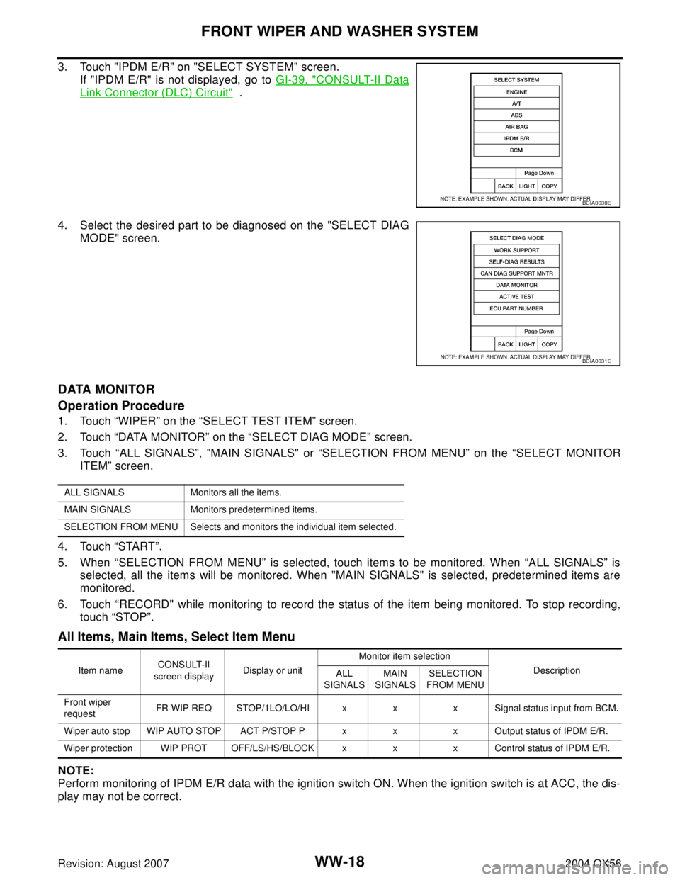
3. Touch "IPDM E/R" on "SELECT SYSTEM" screen.
If "IPDM E/R" is not displayed, go to GI-39, "
CONSULT-II Data
Link Connector (DLC) Circuit" .
4. Select the desired part to be diagnosed on the "SELECT DIAG
MODE" screen.
DATA MONITOR
Operation Procedure
1. Touch “WIPER” on the “SELECT TEST ITEM” screen.
2. Touch “DATA MONITOR” on the “SELECT DIAG MODE” screen.
3. Touch “ALL SIGNALS”, "MAIN SIGNALS" or “SELECTION FROM MENU” on the “SELECT MONITOR
ITEM” screen.
4. Touch “START”.
5. When “SELECTION FROM MENU” is selected, touch items to be monitored. When “ALL SIGNALS” is
selected, all the items will be monitored. When "MAIN SIGNALS" is selected, predetermined items are
monitored.
6. Touch “RECORD" while monitoring to record the status of the item being monitored. To stop recording,
touch “STOP”.
All Items, Main Items, Select Item Menu
NOTE:
Perform monitoring of IPDM E/R data with the ignition switch ON. When the ignition switch is at ACC, the dis-
play may not be correct.
BCIA0030E
BCIA0031E
ALL SIGNALS Monitors all the items.
MAIN SIGNALS Monitors predetermined items.
SELECTION FROM MENU Selects and monitors the individual item selected.
Item nameCONSULT-II
screen displayDisplay or unitMonitor item selection
Description
ALL
SIGNALSMAIN
SIGNALSSELECTION
FROM MENU
Front wiper
requestFR WIP REQ STOP/1LO/LO/HI x x x Signal status input from BCM.
Wiper auto stop WIP AUTO STOP ACT P/STOP P x x x Output status of IPDM E/R.
Wiper protection WIP PROT OFF/LS/HS/BLOCK x x x Control status of IPDM E/R.