Page 1092 of 3371
ENGINE COOLANT
CO-9
C
D
E
F
G
H
I
J
K
L
MA
CO
Revision: August 20072004 QX56
REFILLING ENGINE COOLANT
Refer to MA-13, "REFILLING ENGINE COOLANT" .
FLUSHING COOLING SYSTEM
Refer to MA-14, "FLUSHING COOLING SYSTEM" .
Page 1095 of 3371

CO-12Revision: August 2007
RADIATOR
2004 QX56
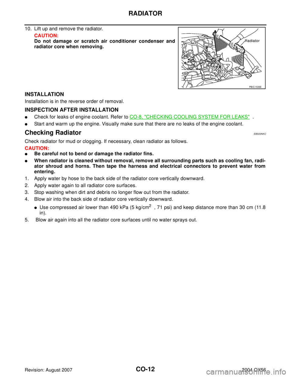
10. Lift up and remove the radiator.
CAUTION:
Do not damage or scratch air conditioner condenser and
radiator core when removing.
INSTALLATION
Installation is in the reverse order of removal.
INSPECTION AFTER INSTALLATION
�Check for leaks of engine coolant. Refer to CO-8, "CHECKING COOLING SYSTEM FOR LEAKS" .
�Start and warm up the engine. Visually make sure that there are no leaks of the engine coolant.
Checking RadiatorEBS00NKC
Check radiator for mud or clogging. If necessary, clean radiator as follows.
CAUTION:
�Be careful not to bend or damage the radiator fins.
�When radiator is cleaned without removal, remove all surrounding parts such as cooling fan, radi-
ator shroud and horns. Then tape the harness and electrical connectors to prevent water from
entering.
1. Apply water by hose to the back side of the radiator core vertically downward.
2. Apply water again to all radiator core surfaces.
3. Stop washing when dirt and debris no longer flow out from the radiator.
4. Blow air into the back side of radiator core vertically downward.
�Use compressed air lower than 490 kPa (5 kg/cm2 , 71 psi) and keep distance more than 30 cm (11.8
in).
5. Blow air again into all the radiator core surfaces until no water sprays out.
PBIC1536E
Page 1096 of 3371

ENGINE COOLING FAN
CO-13
C
D
E
F
G
H
I
J
K
L
MA
CO
Revision: August 20072004 QX56
ENGINE COOLING FANPFP:21140
Removal and Installation (Crankshaft Driven Type)EBS00I51
REMOVAL
1. Remove air duct. Refer to EM-14, "REMOVAL" .
2. Remove the engine front undercover using power tool.
3. Remove the lower radiator shroud. Refer to CO-10, "
RADIATOR" .
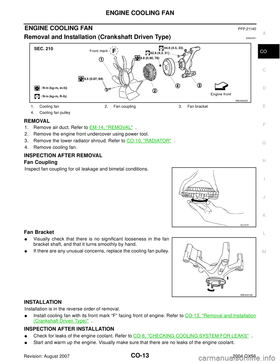
4. Remove cooling fan.
INSPECTION AFTER REMOVAL
Fan Coupling
Inspect fan coupling for oil leakage and bimetal conditions.
Fan Bracket
�Visually check that there is no significant looseness in the fan
bracket shaft, and that it turns smoothly by hand.
�If there are any unusual concerns, replace the cooling fan pulley.
INSTALLATION
Installation is in the reverse order of removal.
�Install cooling fan with its front mark “F” facing front of engine. Refer to CO-13, "Removal and Installation
(Crankshaft Driven Type)" .
INSPECTION AFTER INSTALLATION
�Check for leaks of the engine coolant. Refer to CO-8, "CHECKING COOLING SYSTEM FOR LEAKS" .
�Start and warm up the engine. Visually make sure that there are no leaks of the engine coolant.
1. Cooling fan 2. Fan coupling 3. Fan bracket
4. Cooling fan pulley
WBIA0632E
SL C0 72
WBIA0418E
Page 1099 of 3371
CO-16Revision: August 2007
WATER PUMP
2004 QX56
�For bleeding the air from the cooling system, refer to MA-13, "REFILLING ENGINE COOLANT" .
INSPECTION AFTER INSTALLATION
�Check for leaks of engine coolant. Refer to CO-8, "CHECKING COOLING SYSTEM FOR LEAKS" .
�Start and warm up engine. Visually make sure that there are no leaks of engine coolant.
Page 1101 of 3371

CO-18Revision: August 2007
THERMOSTAT AND WATER PIPING
2004 QX56
CAUTION:
Perform when the engine is cold.
2. Remove air duct and resonator assembly. Refer to EM-14, "
REMOVAL" .
3. Remove engine room cover using power tools.
4. Disconnect heater hose (heater core side).
5. Remove heater hose bracket.
6. Disconnect the water cut valve connector.
7. Remove the water cut valve
INSPECTION AFTER REMOVAL
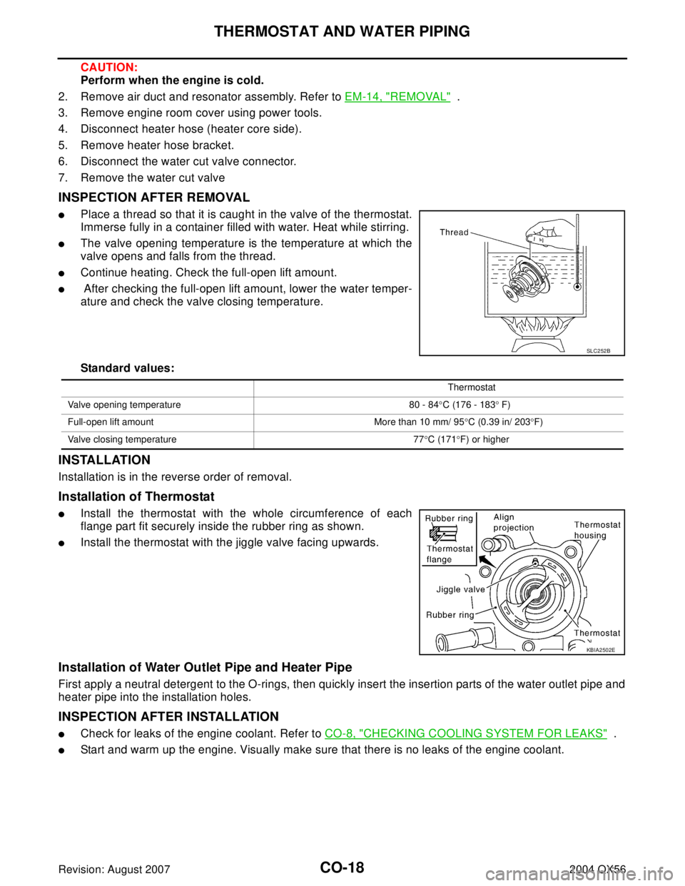
�Place a thread so that it is caught in the valve of the thermostat.
Immerse fully in a container filled with water. Heat while stirring.
�The valve opening temperature is the temperature at which the
valve opens and falls from the thread.
�Continue heating. Check the full-open lift amount.
� After checking the full-open lift amount, lower the water temper-
ature and check the valve closing temperature.
Standard values:
INSTALLATION
Installation is in the reverse order of removal.
Installation of Thermostat
�Install the thermostat with the whole circumference of each
flange part fit securely inside the rubber ring as shown.
�Install the thermostat with the jiggle valve facing upwards.
Installation of Water Outlet Pipe and Heater Pipe
First apply a neutral detergent to the O-rings, then quickly insert the insertion parts of the water outlet pipe and
heater pipe into the installation holes.
INSPECTION AFTER INSTALLATION
�Check for leaks of the engine coolant. Refer to CO-8, "CHECKING COOLING SYSTEM FOR LEAKS" .
�Start and warm up the engine. Visually make sure that there is no leaks of the engine coolant.
SL C2 52 B
Thermostat
Valve opening temperature 80 - 84°C (176 - 183° F)
Full-open lift amount More than 10 mm/ 95°C (0.39 in/ 203°F)
Valve closing temperature 77°C (171°F) or higher
KBIA2502E
Page 1216 of 3371

ENGINE CONTROL SYSTEM
EC-25
C
D
E
F
G
H
I
J
K
L
MA
EC
Revision: August 20072004 QX56
System ChartUBS00GZD
*1: This sensor is not used to control the engine system. This is used only for the on board diagnosis.
*2: This sensor is not used to control the engine system under normal conditions.
*3: This input signal is sent to the ECM through CAN communication line.
*4: This output signal is sent from the ECM through CAN communication line.Input (Sensor) ECM Function Output (Actuator)
�Camshaft position sensor (PHASE)
�Crankshaft position sensor (POS)
�Mass air flow sensor
�Engine coolant temperature sensor
�A/F sensor 1
�Throttle position sensor
�Accelerator pedal position sensor
�Park/neutral position (PNP) switch
�Intake air temperature sensor
�Power steering pressure sensor
�Ignition switch
�Battery voltage
�Knock sensor
�Refrigerant pressure sensor
�Stop lamp switch
�ASCD steering switch
�ASCD brake switch
�Fuel level sensor*1 *3
�EVAP control system pressure sensor
�Fuel tank temperature sensor*1
�Heated oxygen sensor 2*2
�TCM (Transmission control module)*3
�ABS actuator and electric unit (control unit)*3
�Air conditioner switch*3
�Wheel sensor*3
�Electrical load signal*3
Fuel injection & mixture ratio control Fuel injector
Electronic ignition system Power transistor
Nissan torque demand control system
�Electric throttle control actuator
�Fuel injector
Fuel pump control Fuel pump relay
ASCD vehicle speed control Electric throttle control actuator
On board diagnostic system
MIL (On the instrument panel)*
4
A/F sensor 1 heater control A/F sensor 1 heater
Heated oxygen sensor 2 heater control Heated oxygen sensor 2 heater
EVAP canister purge flow controlEVAP canister purge volume control
solenoid valve
Air conditioning cut control
Air conditioner relay*
4
Cooling fan control
Cooling fan relay*4
ON BOARD DIAGNOSIS for EVAP system EVAP canister vent control valve
Page 1268 of 3371

TROUBLE DIAGNOSIS
EC-77
C
D
E
F
G
H
I
J
K
L
MA
EC
Revision: August 20072004 QX56
Fail-safe ChartUBS00GZY
When the DTC listed below is detected, the ECM enters fail-safe mode and the MIL lights up.
2�P0037 P0038 P0057 P0058 Heated oxygen sensor 2 heater
�P0138 P0139 P0158 P0159 P1146 P1147 P1166 P1167 Heated oxygen sensor 2
�P0441 EVAP control system purge flow monitoring
�P0444 P0445 P1444 EVAP canister purge volume control solenoid valve
�P0447 P1446 EVAP canister vent control valve
�P0451 P0452 P0453 EVAP control system pressure sensor
�P0550 Power steering pressure sensor
�P0700 P0710 P0720 P0740 P0744 P0745 P1706 P1716 P1730 P1752 P1754 P1757 P1759 P1762 P1764 P1767
P1769 P1772 P1774 A/T related sensors and solenoid valves
�P1031 P1032 P1051 P1052 A/F sensor 1 heater
�P1065 ECM power supply
�P1122 Electric throttle control function
�P1124 P1126 P1128 Electric throttle control actuator
�P1217 Engine over temperature (OVERHEAT)
�P1271 P1272 P1273 P1274 P1276 P1278 P1279 P1281 P1282 P1283 P1284 P1286 P1288 P1289 A/F sensor 1
�P1805 Brake switch
3
�P0171 P0172 P0174 P0175 Fuel injection system function
�P0300 - P0308 Misfire
�P0420 P0430 Three way catalyst function
�P0442 P0456 EVAP control system (SMALL LEAK, VERY SMALL LEAK)
�P0455 EVAP control system (GROSS LEAK)
�P0506 P0507 Idle speed control system
�P1121 Electric throttle control actuator
�P1148 P1168 Closed loop control
�P1211 TCS control unit
�P1212 TCS communication line
�P1564 ICC steering switch/ASCD steering switch
�P1568 ICC command value
�P1572 ICC brake switch/ASCD brake switch
�P1574 ICC vehicle speed sensor/ASCD vehicle speed sensor Priority Detected items (DTC)
DTC No. Detected items Engine operating condition in fail-safe mode
P0101
P0102
P0103Mass air flow sensor circuit Engine speed will not rise more than 2,400 rpm due to the fuel cut.
P0117
P0118Engine coolant tempera-
ture sensor circuitEngine coolant temperature will be determined by ECM based on the time after turning
ignition switch ON or START.
CONSULT-II displays the engine coolant temperature decided by ECM.
ConditionEngine coolant temperature decided
(CONSULT-II display)
Just as ignition switch is turned
ON or START40°C (104°F)
More than approx. 4 minutes after
ignition ON or START80°C (176°F)
Except as shown above40 - 80°C (104 - 176°F)
(Depends on the time)
When the fail-safe system for engine coolant temperature sensor is activated, the cooling
fan operates while engine is running.
Page 1278 of 3371
TROUBLE DIAGNOSIS
EC-87
C
D
E
F
G
H
I
J
K
L
MA
EC
Revision: August 20072004 QX56
1 - 6: The numbers refer to the order of inspection.Cooling Radiator/Hose/Radiator filler cap
55555 55 45CO-10
Thermostat 5CO-17
Water pum pCO-15
Water galleryCO-6
Cooling fan
5EC-410
Coolant level (Low)/Contami-
nated coolantCO-8
IVIS (Infinti Vehicle Immobilizer System —
NATS)11EC-63 or
BL-138
SYMPTOM
Reference
page
HARD/NO START/RESTART (EXCP. HA)
ENGINE STALL
HESITATION/SURGING/FLAT SPOT
SPARK KNOCK/DETONATION
LACK OF POWER/POOR ACCELERATION
HIGH IDLE/LOW IDLE
ROUGH IDLE/HUNTING
IDLING VIBRATION
SLOW/NO RETURN TO IDLE
OVERHEATS/WATER TEMPERATURE HIGH
EXCESSIVE FUEL CONSUMPTION
EXCESSIVE OIL CONSUMPTION
BATTERY DEAD (UNDER CHARGE)
Warranty symptom code AA AB AC AD AE AF AG AH AJ AK AL AM HA