Page 1273 of 3371

EC-82Revision: August 2007
TROUBLE DIAGNOSIS
2004 QX56
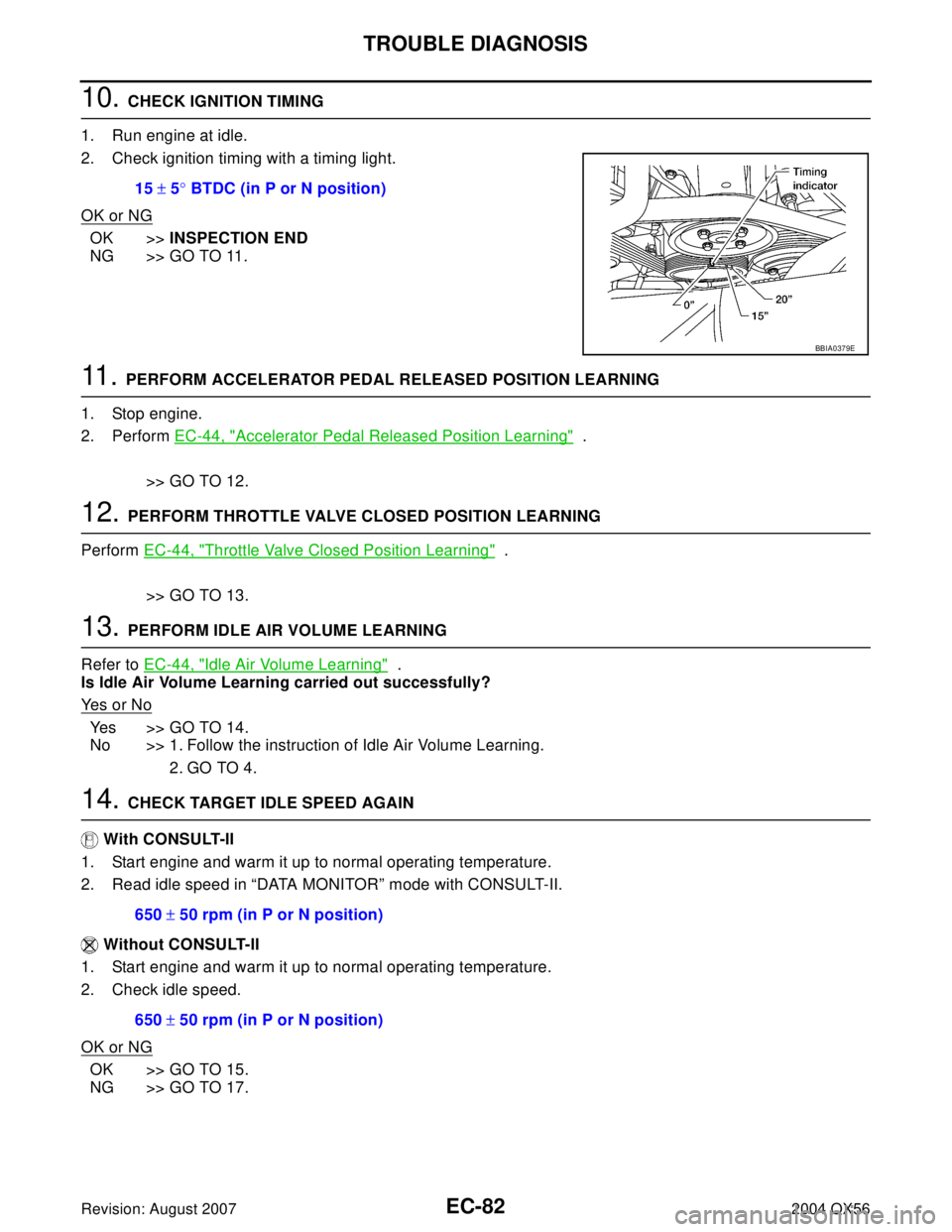
10. CHECK IGNITION TIMING
1. Run engine at idle.
2. Check ignition timing with a timing light.
OK or NG
OK >>INSPECTION END
NG >> GO TO 11.
11 . PERFORM ACCELERATOR PEDAL RELEASED POSITION LEARNING
1. Stop engine.
2. Perform EC-44, "
Accelerator Pedal Released Position Learning" .
>> GO TO 12.
12. PERFORM THROTTLE VALVE CLOSED POSITION LEARNING
Perform EC-44, "
Throttle Valve Closed Position Learning" .
>> GO TO 13.
13. PERFORM IDLE AIR VOLUME LEARNING
Refer to EC-44, "
Idle Air Volume Learning" .
Is Idle Air Volume Learning carried out successfully?
Ye s o r N o
Yes >> GO TO 14.
No >> 1. Follow the instruction of Idle Air Volume Learning.
2. GO TO 4.
14. CHECK TARGET IDLE SPEED AGAIN
With CONSULT-II
1. Start engine and warm it up to normal operating temperature.
2. Read idle speed in “DATA MONITOR” mode with CONSULT-II.
Without CONSULT-II
1. Start engine and warm it up to normal operating temperature.
2. Check idle speed.
OK or NG
OK >> GO TO 15.
NG >> GO TO 17.15 ± 5° BTDC (in P or N position)
BBIA0379E
650 ± 50 rpm (in P or N position)
650 ± 50 rpm (in P or N position)
Page 1274 of 3371

TROUBLE DIAGNOSIS
EC-83
C
D
E
F
G
H
I
J
K
L
MA
EC
Revision: August 20072004 QX56
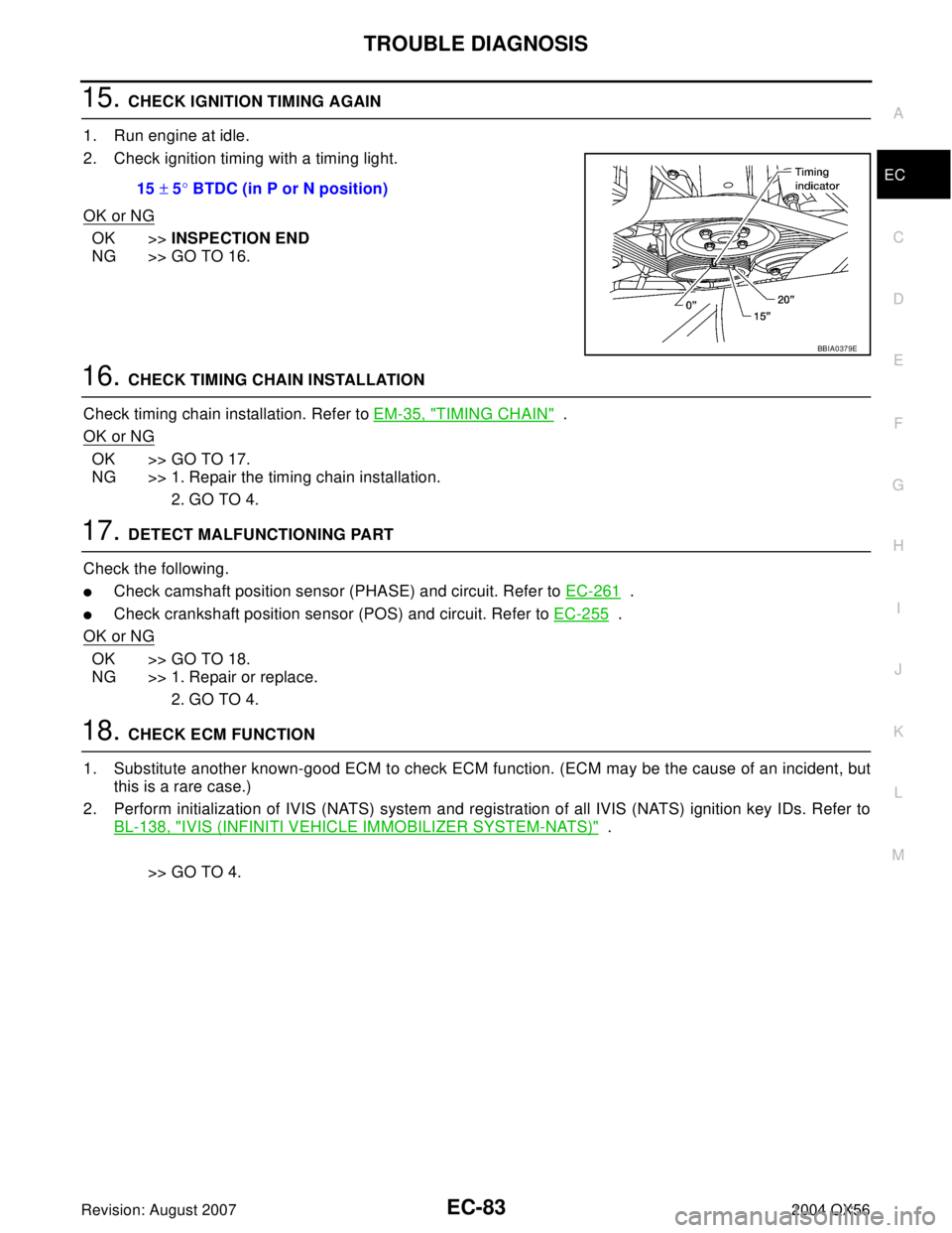
15. CHECK IGNITION TIMING AGAIN
1. Run engine at idle.
2. Check ignition timing with a timing light.
OK or NG
OK >>INSPECTION END
NG >> GO TO 16.
16. CHECK TIMING CHAIN INSTALLATION
Check timing chain installation. Refer to EM-35, "
TIMING CHAIN" .
OK or NG
OK >> GO TO 17.
NG >> 1. Repair the timing chain installation.
2. GO TO 4.
17. DETECT MALFUNCTIONING PART
Check the following.
�Check camshaft position sensor (PHASE) and circuit. Refer to EC-261 .
�Check crankshaft position sensor (POS) and circuit. Refer to EC-255 .
OK or NG
OK >> GO TO 18.
NG >> 1. Repair or replace.
2. GO TO 4.
18. CHECK ECM FUNCTION
1. Substitute another known-good ECM to check ECM function. (ECM may be the cause of an incident, but
this is a rare case.)
2. Perform initialization of IVIS (NATS) system and registration of all IVIS (NATS) ignition key IDs. Refer to
BL-138, "
IVIS (INFINITI VEHICLE IMMOBILIZER SYSTEM-NATS)" .
>> GO TO 4. 15 ± 5° BTDC (in P or N position)
BBIA0379E
Page 1303 of 3371

EC-112Revision: August 2007
TROUBLE DIAGNOSIS
2004 QX56
ACTIVE TEST MODE
Test Item
*: Leaving cooling fan OFF with CONSULT-II while engine is running may cause the engine to overheat.
DTC & SRT CONFIRMATION MODE
SRT STATUS Mode
For details, refer to EC-55, "SYSTEM READINESS TEST (SRT) CODE" .
SRT Work Support Mode
This mode enables a technician to drive a vehicle to set the SRT while monitoring the SRT status.
TEST ITEM CONDITION JUDGEMENT CHECK ITEM (REMEDY)
FUEL INJEC-
TION
�Engine: Return to the original
trouble condition
�Change the amount of fuel injec-
tion using CONSULT-II.If trouble symptom disappears, see
CHECK ITEM.
�Harness and connectors
�Fuel injector
�Air fuel ratio (A/F) sensor 1
IGNITION TIM-
ING
�Engine: Return to the original
trouble condition
�Timing light: Set
�Retard the ignition timing using
CONSULT-II.If trouble symptom disappears, see
CHECK ITEM.
�Perform Idle Air Volume Learning.
POWER BAL-
ANCE
�Engine: After warming up, idle
the engine.
�A/C switch OFF
�Shift lever N
�Cut off each injector signal one at
a time using CONSULT-II.Engine runs rough or dies.
�Harness and connectors
�Compression
�Fuel injector
�Power transistor
�Spark plug
�Ignition coil
COOLING FAN*
�Ignition switch: ON
�Turn the cooling fan ON and OFF
using CONSULT-II.Cooling fan moves and stops.
�Harness and connectors
�Cooling fan motor
�IPDM E/R
ENG COOLANT
TEMP
�Engine: Return to the original
trouble condition
�Change the engine coolant tem-
perature using CONSULT-II.If trouble symptom disappears, see
CHECK ITEM.
�Harness and connectors
�Engine coolant temperature sen-
sor
�Fuel injector
FUEL PUMP
RELAY
�Ignition switch: ON (Engine
stopped)
�Turn the fuel pump relay ON and
OFF using CONSULT-II and lis-
ten to operating sound.Fuel pump relay makes the operat-
ing sound.�Harness and connectors
�Fuel pump relay
PURG VOL
CONT/V
�Engine: After warming up, run
engine at 1,500 rpm.
�Change the EVAP canister purge
volume control solenoid valve
opening percent using CON-
SULT-II.Engine speed changes according to
the opening percent.�Harness and connectors
�Solenoid valve
FUEL/T TEMP
SEN
�Change the fuel tank temperature using CONSULT-II.
VENT CON-
TROL/V
�Ignition switch: ON (Engine
stopped)
�Turn solenoid valve ON and OFF
with the CONSULT-II and listen
to operating sound.Solenoid valve makes an operating
sound.�Harness and connectors
�Solenoid valve
Page 1320 of 3371

POWER SUPPLY AND GROUND CIRCUIT
EC-129
C
D
E
F
G
H
I
J
K
L
MA
EC
Revision: August 20072004 QX56
Specification data are reference values and are measured between each terminal and ground.
CAUTION:
Do not use ECM ground terminals when measuring input/output voltage. Doing so may result in dam-
age to the ECM's transistor. Use a ground other than ECM terminals, such as the ground.
Diagnostic ProcedureUBS00H0G
1. INSPECTION START
Start engine.
Is engine running?
Ye s o r N o
Yes >> GO TO 9.
No >> GO TO 2.
2. CHECK 10A FUSE
1. Turn ignition switch OFF.
2. Check 10A fuse (No. 59, located in the fuse and relay box).
OK or NG
OK >> Reinstall fuse. GO TO 3.
NG >>
�Repair harness or connectors
�Replace fuse
3. CHECK ECM POWER SUPPLY CIRCUIT-I
1. Turn ignition switch ON.
2. Check voltage between ECM terminal 109 and ground with
CONSULT-II or tester.
OK or NG
OK >> GO TO 5.
NG >> GO TO 4.
TER-
MINAL
NO.WIRE
COLORITEM CONDITION DATA (DC Voltage)
1 B ECM ground[Engine is running]
�Idle speedBody ground
109 B/R Ignition switch[Ignition switch: OFF]0V
[Ignition switch: ON]BATTERY VOLTAGE
(11 - 14V)
111 W / BECM relay
(Self shut-off)[Engine is running]
[Ignition switch: OFF]
�For a few seconds after turning ignition
switch OFF0 - 1.5V
[Ignition switch: OFF]
�More than a few seconds after turning igni-
tion switch OFFBATTERY VOLTAGE
(11 - 14V)
11 5
11 6B
B/WECM ground[Engine is running]
�Idle speedBody ground
11 9
120BR
BRPower supply for ECM[Ignition switch: ON]BATTERY VOLTAGE
(11 - 14V)
Voltage: Battery voltage
MBIB0015E
Page 1334 of 3371

DTC P0037, P0038, P0057, P0058 HO2S2 HEATER
EC-143
C
D
E
F
G
H
I
J
K
L
MA
EC
Revision: August 20072004 QX56
Specification data are reference values and are measured between each terminal and ground.
CAUTION:
Do not use ECM ground terminals when measuring input/output voltage. Doing so may result in dam-
age to the ECM's transistor. Use a ground other than ECM terminals, such as the ground.
Diagnostic ProcedureUBS00H0S
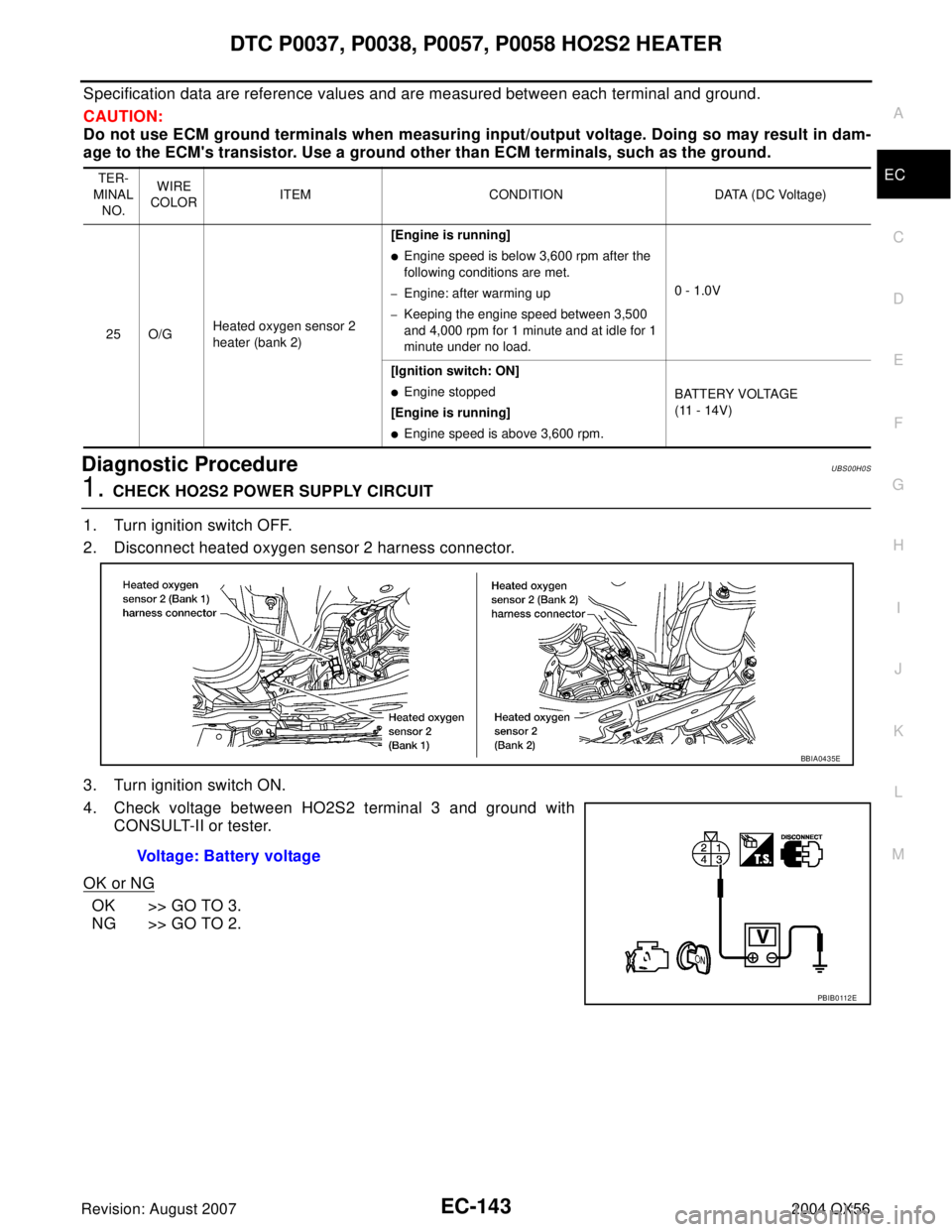
1. CHECK HO2S2 POWER SUPPLY CIRCUIT
1. Turn ignition switch OFF.
2. Disconnect heated oxygen sensor 2 harness connector.
3. Turn ignition switch ON.
4. Check voltage between HO2S2 terminal 3 and ground with
CONSULT-II or tester.
OK or NG
OK >> GO TO 3.
NG >> GO TO 2.
TER-
MINAL
NO.WIRE
COLORITEM CONDITION DATA (DC Voltage)
25 O/GHeated oxygen sensor 2
heater (bank 2)[Engine is running]
�Engine speed is below 3,600 rpm after the
following conditions are met.
–Engine: after warming up
–Keeping the engine speed between 3,500
and 4,000 rpm for 1 minute and at idle for 1
minute under no load.0 - 1.0V
[Ignition switch: ON]
�Engine stopped
[Engine is running]
�Engine speed is above 3,600 rpm.BATTERY VOLTAGE
(11 - 14V)
BBIA0435E
Voltage: Battery voltage
PBIB0 112 E
Page 1338 of 3371

DTC P0101 MAF SENSOR
EC-147
C
D
E
F
G
H
I
J
K
L
MA
EC
Revision: August 20072004 QX56
DTC Confirmation ProcedureUBS00H0Y
Perform PROCEDURE FOR MALFUNCTION A first.
If the DTC cannot be confirmed, perform PROCEDURE FOR MALFUNCTION B.
NOTE:
If DTC Confirmation Procedure has been previously conducted, always turn ignition switch OFF and wait at
least 10 seconds before conducting the next test.
PROCEDURE FOR MALFUNCTION A
NOTE:
If engine will not start or stops soon, wait at least 10 seconds with engine stopped (Ignition switch ON) instead
of running engine at idle speed.
With CONSULT-II
1. Turn ignition switch ON.
2. Select “DATA MONITOR” mode with CONSULT-II.
3. Start engine and warm it up to normal operating temperature.
4. Run engine for at least 10 seconds at idle speed.
5. If DTC is detected, go to EC-150, "
Diagnostic Procedure" .
With GST
Follow the procedure “With CONSULT-II” above.
PROCEDURE FOR MALFUNCTION B
CAUTION:
Always drive vehicle at a safe speed.
With CONSULT-II
1. Turn ignition switch ON.
2. Start engine and warm it up to normal operating temperature.
If engine cannot be started, go to EC-150, "
Diagnostic Procedure" .
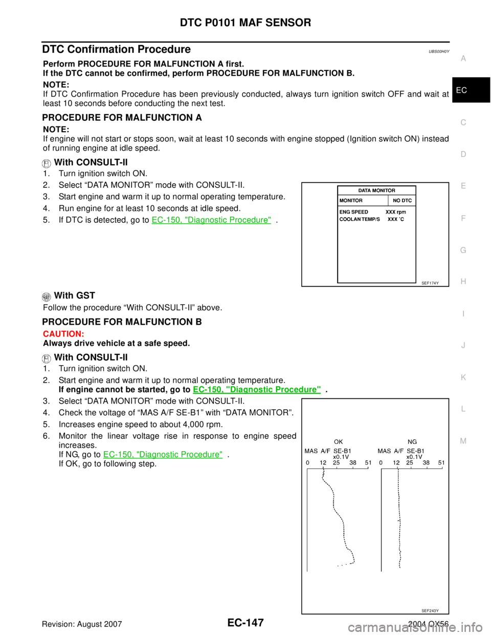
3. Select “DATA MONITOR” mode with CONSULT-II.
4. Check the voltage of “MAS A/F SE-B1” with “DATA MONITOR”.
5. Increases engine speed to about 4,000 rpm.
6. Monitor the linear voltage rise in response to engine speed
increases.
If NG, go to EC-150, "
Diagnostic Procedure" .
If OK, go to following step.
SEF 1 74 Y
SEF 2 43 Y
Page 1339 of 3371
EC-148Revision: August 2007
DTC P0101 MAF SENSOR
2004 QX56
7. Maintain the following conditions for at least 10 consecutive sec-
onds.
8. If DTC is detected, go to EC-150, "
Diagnostic Procedure" .
Overall Function CheckUBS00H0Z
PROCEDURE FOR MALFUNCTION B
Use this procedure to check the overall function of the mass air flow sensor circuit. During this check, a DTC
might not be confirmed.
With GST
1. Start engine and warm it up to normal operating temperature.
2. Select MODE 1 with GST.
3. Check the mass air flow sensor signal with MODE 1.
4. Check for linear mass air flow sensor signal value rise in
response to increases to about 4,000 rpm in engine speed.
5. If NG, go to EC-150, "
Diagnostic Procedure" .
ENG SPEED More than 2,000 rpm
THRTL SEN 1 More than 3V
THRTL SEN 2 More than 3V
Selector lever Suitable position
Driving locationDriving vehicle uphill (Increased engine load) will help
maintain the driving conditions required for this test.
PBIB0199E
SEF 5 34 P
Page 1341 of 3371

EC-150Revision: August 2007
DTC P0101 MAF SENSOR
2004 QX56
Specification data are reference values and are measured between each terminal and ground.
CAUTION:
Do not use ECM ground terminals when measuring input/output voltage. Doing so may result in dam-
age to the ECM's transistor. Use a ground other than ECM terminals, such as the ground.
Diagnostic ProcedureUBS00H11
1. INSPECTION START
Which malfunction (A or B) is duplicated?
A or B
A >> GO TO 3.
B >> GO TO 2.
2. CHECK INTAKE SYSTEM
Check the following for connection.
�Air duct
�Vacuum hoses
�Intake air passage between air duct to intake manifold
OK or NG
OK >> GO TO 3.
NG >> Reconnect the parts.
TER-
MINAL
NO.WIRE
COLORITEM CONDITION DATA (DC Voltage)
51 W Mass air flow sensor[Engine is running]
�Warm-up condition
�Idle speed1.1 - 1.4V
[Engine is running]
�Warm-up condition
�Engine speed is 2,500 rpm.1.7 - 2.0V
67 B Sensor ground[Engine is running]
�Warm-up condition
�Idle speedApproximately 0V
111 W /BECM relay
(Self shut-off)[Engine is running]
[Ignition switch: OFF]
�For a few seconds after turning ignition
switch OFF0 - 1.5V
[Ignition switch: OFF]
�More than a few seconds after turning igni-
tion switch OFFBATTERY VOLTAGE
(11 - 14V)
11 9
120BR
BRPower supply for ECM[Ignition switch: ON]BATTERY VOLTAGE
(11 - 14V)