Page 3241 of 3371
TF-116
CENTER CASE
Revision: August 20072004 QX56
MAINSHAFT AND CLUTCH DRUM
1. Set center case on press stand. Remove mainshaft from center
case.
2. Remove thrust needle bearing from press flange.
3. Remove snap ring from mainshaft, using suitable tool.
4. Press flange as shown, using Tool. Press drift until snap ring is
out of place.
SDIA2108E
SDIA2109E
SDIA2 110 E
Tool number
A : ST22452000 (J-34335)
B : ST30911000 ( — )
C : KV31103300 ( — )
SD I A 2 111E
Page 3242 of 3371
CENTER CASE
TF-117
C
E
F
G
H
I
J
K
L
MA
B
TF
Revision: August 20072004 QX56
5. Remove snap ring from mainshaft, using suitable tool.
6. Remove press flange from mainshaft.
7. Remove return spring assembly from clutch hub.
8. Remove each plate from clutch drum.
9. Remove snap ring from mainshaft.
SDIA2 112 E
SMT910C
SM T9 11 C
SMT912C
SDIA2 113 E
Page 3243 of 3371
TF-118
CENTER CASE
Revision: August 20072004 QX56
10. Tap mainshaft, using suitable tool to remove it from clutch drum
and clutch hub.
11. Remove needle bearing and spacer from the mainshaft.
12. Remove the snap ring from the clutch hub.
CLUTCH PISTON
1. Remove oil pressure check plug from oil pressure check port.
2. Apply air gradually from oil pressure check port, and remove
clutch piston from center case.
SMT914C
WDIA0101E
SDIA2 115 E
SDIA2 116 E
Page 3244 of 3371
CENTER CASE
TF-119
C
E
F
G
H
I
J
K
L
MA
B
TF
Revision: August 20072004 QX56
3. Remove the two D-rings from clutch piston.
4. Remove thrust needle bearing race from clutch piston, using
suitable tool by hooking a edge into 3 notches of thrust needle
bearing race.
CAUTION:
Be careful not to damage the clutch piston.
CONTROL VALVE
CAUTION:
�Do not reuse any part that has been dropped or damaged.
�Make sure valve is assembled in the proper direction.
�Do not use a magnet because residual magnetism stays during disassembly.
1. Remove two bolts, and remove oil strainer.
2. Remove two O-rings from oil strainer.
SDIA2 117 E
SDIA2 118 E
SDIA2 119 E
SDIA2120E
Page 3245 of 3371
TF-120
CENTER CASE
Revision: August 20072004 QX56
3. Remove control valve assembly bolts.
4. Remove snap ring. Then push connector assembly into center
case to remove control valve assembly.
5. Remove lip seals from center case.
CAUTION:
There are two kinds of lip seals (lip seal of large inner diam-
eter: 5 pieces, lip seal of small inner diameter: 2 pieces).
Confirm the position before disassembly.
6. Remove all bolts except for the two as shown.
7. Remove 4WD solenoid valve, clutch pressure switch, 2-4WD
shift solenoid valve, line pressure switch, and transfer fluid tem-
perature sensor from control valve assembly.
SDIA2121E
SDIA2122E
SDIA2123E
SDIA2124E
PDIA0183E
Page 3258 of 3371

CENTER CASE
TF-133
C
E
F
G
H
I
J
K
L
MA
B
TF
Revision: August 20072004 QX56
CENTER CASEPFP:33105
InspectionEDS00192
BEARINGS
1. Make sure bearings roll freely and are free from noise, pitting
and cracks.
SUB-OIL PUMP
1. Check inner and outer circumference, tooth face, and side-face
of inner and outer gears for damage or abnormal wear.
2. Measure side clearance between sub oil pump housing edge
and inner gear/outer gear.
3. Make sure side clearance is within specification. If the measure-
ment is out of specification, replace inner and outer gears
together with new ones as a set.
MAIN OIL PUMP
1. Check inner and outer circumference, tooth face, and side-face
of inner and outer gears for damage or abnormal wear.
2. Measure side clearance between main oil pump housing edge
and inner gear/outer gear.
3. Make sure side clearance is within specification. If the measure-
ment is out of specification, replace inner and outer gears with
new ones as a set.
MAINSHAFT
�Check surfaces which contact sun gear, clutch drum, clutch hub,
press flange, clutch piston, each bearing, etc. for damage, peel,
partial wear, dents, bending, or other abnormal damage. If any is
found, replace with new one.
SDIA2175E
Specification : 0.015 - 0.035 mm (0.0006 - 0.0014 in)
SDIA2173E
Specification : 0.015 - 0.035 mm (0.0006 - 0.0014 in)
SDIA2174E
SMT944C
Page 3259 of 3371

TF-134
CENTER CASE
Revision: August 20072004 QX56
CONTROL VALVE
�Check resistance between terminals of 4WD solenoid valve, 2-
4WD shift solenoid valve and transfer fluid temperature sensor.
Refer to TF-95, "
Component Inspection" .
�Check sliding faces of control valves and plugs for abnormality.
If any is found, replace the control valve assembly with new one.
Refer to TF-154, "
Control Valve" .
CAUTION:
Replace control valve body together with clutch return
spring as a set.
�Check each control valve spring for damage or distortion, and
also check its free length, outer diameter and wire diameter. If
any damage or fatigue is found, replace control valve body with
new one. Refer to TF-154, "
Control Valve" .
CAUTION:
Replace control valve body together with clutch return spring
as a set.
CLUTCH
�Check drive plate facings and driven plate for damage, cracks or
other abnormality. If any abnormalities are found, replace with
new one.
�Check the thickness of drive plate facings and driven plate.
Refer to TF-153, "
CLUTCH" .
CAUTION:
�Measure facing thickness at 3 points to take an average.
�Check all the drive and driven plates.
�Check return spring for damage or deformation.
�Do not remove spring from the plate
PDIA0183E
SMT947C
SMT948C
SMT949C
Page 3260 of 3371
CENTER CASE
TF-135
C
E
F
G
H
I
J
K
L
MA
B
TF
Revision: August 20072004 QX56
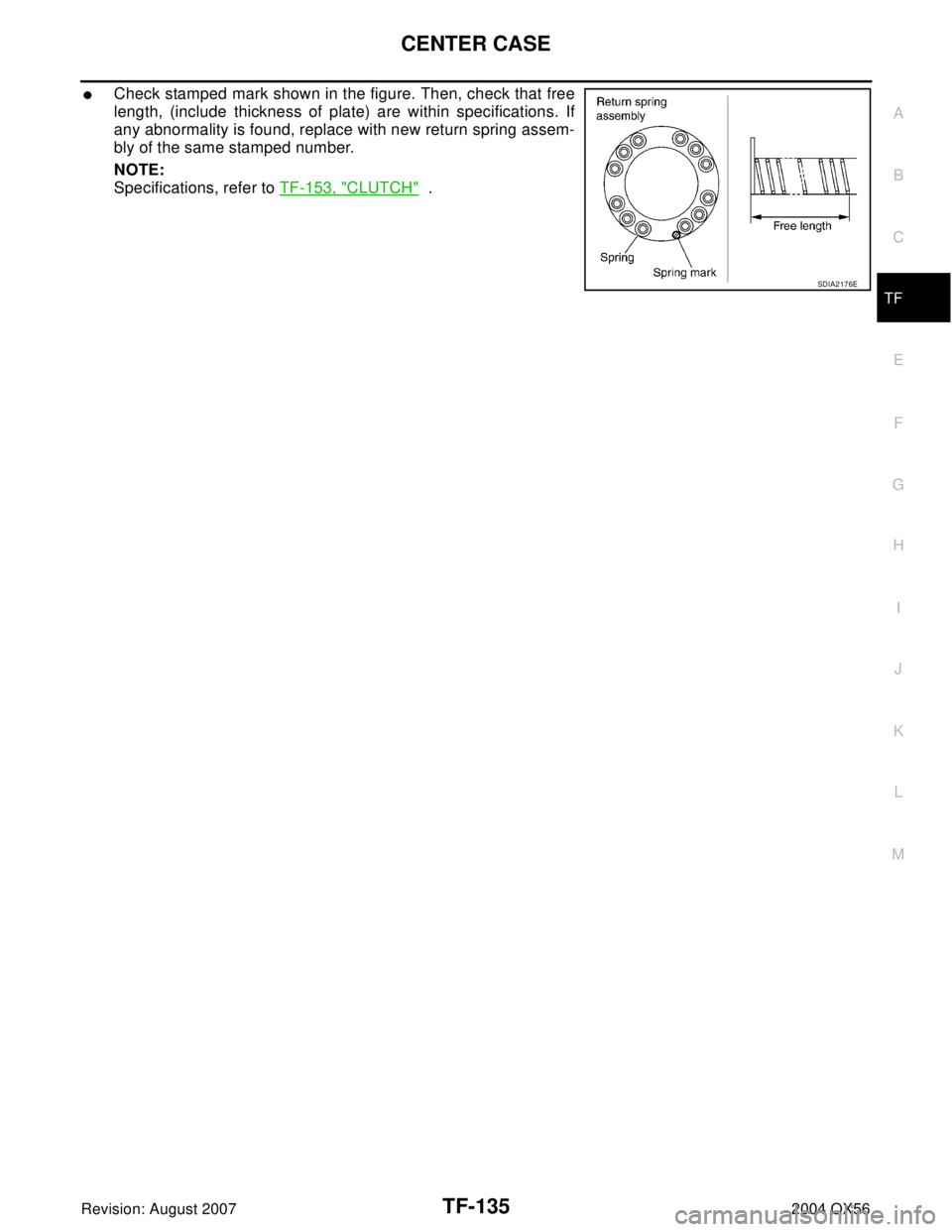
�Check stamped mark shown in the figure. Then, check that free
length, (include thickness of plate) are within specifications. If
any abnormality is found, replace with new return spring assem-
bly of the same stamped number.
NOTE:
Specifications, refer to TF-153, "
CLUTCH" .
SDIA2176E