Page 2779 of 3371

PS-28
POWER STEERING OIL PUMP
Revision: August 20072004 QX56
6. Remove snap ring from drive shaft assembly, then press out
drive shaft assembly.
CAUTION:
When removing snap ring, be careful not to damage drive
shaft assembly.
7. Using a screwdriver, remove oil seal from body assembly.
8. Remove O-ring from body assembly.
9. Remove connector bolt, then flow control valve and spring from
body assembly.
CAUTION:
Be careful not to drop and deform the flow control valve.
10. Remove suction pipe from body assembly.
11. Remove O-ring for suction pipe.
INSPECTION AFTER DISASSEMBLY
Body Assembly and Rear Cover Inspection
�Check body assembly and the inside of rear cover for damage. If any damage is found, replace with new
part for rear cover and replace with new power steering pump assembly for body assembly.
Cartridge Assembly Inspection
�Check cam ring, side plate, rotor and vane for damage. If any damage is found, replace cartridge assem-
bly with new one.
ASSEMBLY
CAUTION:
When retaining drive shaft assembly in a vise, always use copper or aluminum plates between vise
and shaft.
NOTE:
Mount the oil pump in a vise as needed.
1. Apply a coat of Genuine NISSAN PSF or equivalent to oil seal lip and to the circumference of oil seal.
Refer to MA-10, "
RECOMMENDED FLUIDS AND LUBRICANTS" .
SST 0 10 B
SST 0 34 A
SGIA0524E
Page 2781 of 3371
PS-30
POWER STEERING OIL PUMP
Revision: August 20072004 QX56
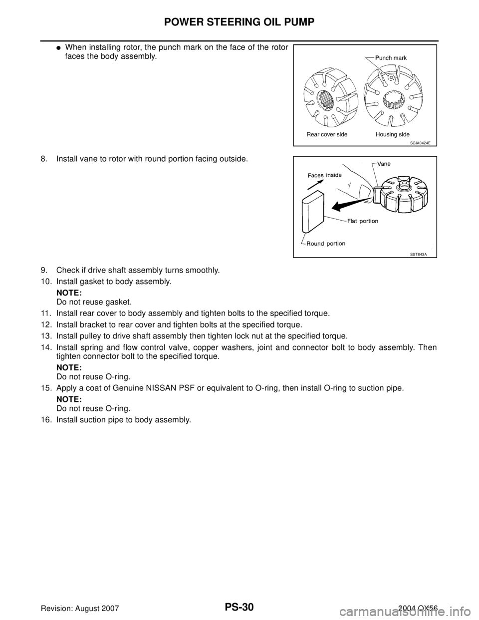
�When installing rotor, the punch mark on the face of the rotor
faces the body assembly.
8. Install vane to rotor with round portion facing outside.
9. Check if drive shaft assembly turns smoothly.
10. Install gasket to body assembly.
NOTE:
Do not reuse gasket.
11. Install rear cover to body assembly and tighten bolts to the specified torque.
12. Install bracket to rear cover and tighten bolts at the specified torque.
13. Install pulley to drive shaft assembly then tighten lock nut at the specified torque.
14. Install spring and flow control valve, copper washers, joint and connector bolt to body assembly. Then
tighten connector bolt to the specified torque.
NOTE:
Do not reuse O-ring.
15. Apply a coat of Genuine NISSAN PSF or equivalent to O-ring, then install O-ring to suction pipe.
NOTE:
Do not reuse O-ring.
16. Install suction pipe to body assembly.
SGIA0424E
SST 8 43 A
Page 2837 of 3371

RFD-6
FRONT OIL SEAL
Revision: August 20072004 QX56
FRONT OIL SEALPFP:38189
Removal and InstallationEDS002JK
REMOVAL
1. Remove the drive shaft inside flange bolts to disconnect the rear drive shafts from the rear final drive.
Support the rear drive shafts using suitable wire.
NOTE:
Disconnecting the rear drive shafts is necessary to measure the total preload accurately.
2. Remove the rear propeller shaft. Refer to PR-8, "
Removal and Installation" .
CAUTION:
Do not damage the propeller shaft tube.
3. Check the total preload. Refer to RFD-12, "
TOTAL PRELOAD" .
4. Put a mark on the end of the drive pinion corresponding to the
position mark “B” on the companion flange as shown.
CAUTION:
�Use paint to make the matching mark “B” on the drive
pinion. Never damage the drive pinion.
�The mark “B” on the companion flange indicates the
maximum vertical runout position.
5. Remove drive pinion nut using Tool as shown.
�Discard the drive pinion nut and use a new drive pinion nut for
installation.
6. Use a suitable puller to remove the companion flange as shown.
SDIA0270E
Tool number : KV40104000 ( — )
LDIA0105E
LDIA0106E
Page 2838 of 3371

FRONT OIL SEAL
RFD-7
C
E
F
G
H
I
J
K
L
MA
B
RFD
Revision: August 20072004 QX56
7. Remove the front oil seal using Tool as shown.
INSTALLATION
1. Apply multi-purpose grease to the sealing lips of the new oil
seal, then press the front oil seal into the carrier using Tool as
shown.
CAUTION:
�Keep the oil seal even when installing, do not tilt the oil
seal when pressing it in.
�Discard the old oil seal, always install a new oil seal.
2. Align the matching mark of the drive pinion with the matching
mark “B” of the companion flange as shown, then install the
companion flange.
3. Apply oil or multi-purpose grease on the drive pinion threads
and the seating surface of drive pinion nut.
4. Install drive pinion nut using Tool.
�Tighten the drive pinion nut to the minimum specified torque.
Final drive pinion nut torque will be determined when adjust-
ing the total preload. Refer to RFD-12, "
TOTAL PRELOAD" .
CAUTION:
The drive pinion nut is not reusable. Use a new drive pinion
nut for installation.
5. Install the rear propeller shaft. Refer to PR-8, "
Removal and Installation" .
6. Connect the rear drive shafts to the rear final drive. Tighten the drive shaft inside flange bolts to specifica-
tion.
7. Check the rear final drive fluid and add fluid as necessary. Refer to MA-24, "
Checking Final Drive Oil" . Tool number : ST33290001 (J-34286)
LDIA0107E
Tool number : ST15310000 ( — )
LDIA0108E
SDIA0270E
Tool number : KV40104000 ( — )
Drive pinion nut : 167 - 372 N·m (17 - 38 kg-m,
124 - 274 ft-lb)
LDIA0105E
Drive shaft inside flange bolt : 118 N·m (12 kg-m, 87 ft-lb)
Page 2840 of 3371
SIDE OIL SEAL
RFD-9
C
E
F
G
H
I
J
K
L
MA
B
RFD
Revision: August 20072004 QX56
4. Check measurement “A” after the side flange installation is com-
plete as shown.
5. Connect the rear drive shafts to the rear final drive. Tighten the drive shaft inside flange bolts to specifica-
tion.Measurement “A” : approx. 339.5 mm (13.37 in)
SDIA1039E
Drive shaft inside flange bolts : 118 N·m (12 kg-m, 87 lb-ft)
Page 2842 of 3371
REAR FINAL DRIVE ASSEMBLY
RFD-11
C
E
F
G
H
I
J
K
L
MA
B
RFD
Revision: August 20072004 QX56
INSTALLATION
Installation is in the reverse order of removal.
CAUTION:
After installation, check the final drive oil level. Refer to MA-24, "
Checking Final Drive Oil" .
ComponentsEDS002JN
R230 2–PINION
WDIA0294E
1. Drive pinion nut 2. Companion flange 3. Front oil seal
4. Pinion front bearing 5. Pinion bearing adjusting spacer (col-
lapsible spacer)6. Pinion rear bearing
7. Pinion height adjusting washer 8. Drive pinion 9. Gear carrier
10. Drive gear 11. Pinion mate shaft 12. Lock pin
13. Pinion mate gear 14. Pinion mate thrust washer 15. Side gear
16. Side gear thrust washer 17. Differential case 18. Side bearing
Page 2843 of 3371

RFD-12
REAR FINAL DRIVE ASSEMBLY
Revision: August 20072004 QX56
CAUTION:
Final drive pinion nut torque will be determined when adjusting the total preload. Refer to RFD-12,
"TOTAL PRELOAD" .
Pre-InspectionEDS002JO
Before disassembling the rear final drive, perform the following inspections.
TOTAL PRELOAD
1. Turn the drive pinion in both directions several times to set the
bearing rollers.
2. Check the total preload using Tool.
DRIVE GEAR TO DRIVE PINION BACKLASH
Check the drive gear to drive pinion backlash using a dial gauge at
several points as shown.
DRIVE GEAR RUNOUT
Check the runout of the drive gear using a dial gauge as shown.
19. Side bearing adjusting washer 20. Bearing cap 21. Rear cover
22. Filler plug 23. Drain plug 24. Side oil seal
Tool number : ST3127S000 (J-25765-A)
Total preload : 2.05 - 4.11 N·m (0.21 - 0.42 kg-m,
19 - 36 in-lb)
SPD8 84
Drive gear to drive pinion backlash : 0.13 - 0.18 mm
(0.0051 - 0.0070 in)
SPD5 13
Runout limit : 0.05 mm (0.0020 in) or less
SPD8 86
Page 2848 of 3371
REAR FINAL DRIVE ASSEMBLY
RFD-17
C
E
F
G
H
I
J
K
L
MA
B
RFD
Revision: August 20072004 QX56
4. Drive the pinion mate shaft lock pin out using a suitable punch,
from the drive gear side.
INSPECTION
Contact Surfaces
1. Clean the disassembled parts in a suitable solvent and blow dry using compressed air.
2. If the following surfaces are burred or scratched, smooth them using an oil stone.
�Differential case
�Side gear
�Pinion mate gear
�Pinion mate shaft
Bearing
1. Thoroughly clean the bearing.
2. Check the bearing for wear, scratches, pitting, or flaking.
3. Check the tapered roller bearing for smooth rotation. If dam-
aged, replace the outer race and inner race as a set.
ADJUSTMENT OF DIFFERENTIAL CASE
Thrust Washer Selection
1. Install the side gears, pinion mate gears, and thrust washers into
the differential case.
SPD0 25
SPD7 15
SPD5 52