Page 2851 of 3371
RFD-20
REAR FINAL DRIVE ASSEMBLY
Revision: August 20072004 QX56
1. Thoroughly clean the drive gear and drive pinion teeth.
2. Lightly apply a mixture of powdered ferric oxide and oil or the
equivalent. Apply it to 3 or 4 teeth of the drive gear drive side.
3. Use your hand to hold the companion flange steady and rotate
the drive gear in both directions.
4. Check the tooth contact as shown.
ASSEMBLY OF DIFFERENTIAL CASE ASSEMBLY
1. Install the pinion mate shaft lock pin using a suitable punch as
shown.
The lock pin must be flush with the case.
2. Place the differential case on the drive gear.
SPD3 57
SDIA0813E
SDIA1910E
SPD0 30
Page 2853 of 3371

RFD-22
REAR FINAL DRIVE ASSEMBLY
Revision: August 20072004 QX56
3. Install the selected pinion height adjusting washer in the drive
pinion. Using a suitable press and Tool, press-fit pinion rear
bearing inner race into the drive pinion.
4. Apply multi-purpose grease to the pinion rear bearing inner race
and pinion front bearing inner race.
5. Set the drive pinion assembly in the differential carrier as shown,
and install drive pinion using a suitable press and suitable tool.
Stop when drive pinion touches the bearing.
6. Install the front oil seal using Tool. Refer to RFD-6, "
Removal and Installation" .
7. Install the companion flange, and tighten the pinion nut to a min-
imum using Tool. Check that the threaded portion of the drive
pinion and drive pinion nut are free of oil or grease.
CAUTION:
The drive pinion nut is not reusable. Use a new drive pinion
nut for installation. Tool number : ST30022000 ( — )
SPD3 77
SDIA0826E
SPD8 96
Tool number : KV40104000 ( — )
SDIA11 45 E
Page 2854 of 3371

REAR FINAL DRIVE ASSEMBLY
RFD-23
C
E
F
G
H
I
J
K
L
MA
B
RFD
Revision: August 20072004 QX56
8. Tighten the drive pinion nut by very small increments until the
specified preload is achieved, when checking the preload, turn
drive pinion in both directions several times.
�If the pinion bearing preload is less than specification, tighten
the drive pinion nut.
�If pinion bearing preload is greater than specification, replace
the pinion bearing adjusting spacer.
INSTALLATION OF DIFFERENTIAL CASE ASSEMBLY
1. Select the side bearing adjusting washer. Refer to RFD-18, "SIDE BEARING PRELOAD" .
2. Install the differential case assembly with side bearing outer
races into the gear carrier.
3. Insert the left and right side bearing adjusting washers into place
between the side bearings and the gear carrier.
4. Install the side bearing caps. Align the matching mark on the
bearing cap with the matching mark on the gear carrier, and
tighten the bearing cap bolts to specification.
5. Install the side oil seals. Refer to RFD-8, "
Removal and Installa-
tion" . Tool number : ST3127S000 (J-25765-A)
Pinion bearing
preload: 1.77 - 2.64 N·m (0.18 - 0.26 kg-m,
16 - 23 in-lb)
SPD8 84
SPD9 19
SPD9 24
Bearing cap bolts : 93 N·m (9.5 kg-m, 69 ft-lb)
SPD8 89
Page 2862 of 3371
 “AIR BAG” and “SEAT
BELT PRE-TENSIONER”
EE")
PRECAUTIONS
RSU-3
C
D
F
G
H
I
J
K
L
MA
B
RSU
Revision: August 20072004 QX56
PRECAUTIONSPFP:00001
Precautions for Supplemental Restraint System (SRS) “AIR BAG” and “SEAT
BELT PRE-TENSIONER”
EES0010X
The Supplemental Restraint System such as “AIR BAG” and “SEAT BELT PRE-TENSIONER”, used along
with a front seat belt, helps to reduce the risk or severity of injury to the driver and front passenger for certain
types of collision. This system includes seat belt switch inputs and dual stage front air bag modules. The SRS
system uses the seat belt switches to determine the front air bag deployment, and may only deploy one front
air bag, depending on the severity of a collision and whether the front occupants are belted or unbelted.
Information necessary to service the system safely is included in the SRS and SB section of this Service Man-
ual.
WA RN ING:
�To avoid rendering the SRS inoperative, which could increase the risk of personal injury or death
in the event of a collision which would result in air bag inflation, all maintenance must be per-
formed by an authorized NISSAN/INFINITI dealer.
�Improper maintenance, including incorrect removal and installation of the SRS, can lead to per-
sonal injury caused by unintentional activation of the system. For removal of Spiral Cable and Air
Bag Module, see the SRS section.
�Do not use electrical test equipment on any circuit related to the SRS unless instructed to in this
Service Manual. SRS wiring harnesses can be identified by yellow and/or orange harnesses or
harness connectors.
Precautions for Rear SuspensionEES0010Y
�When installing the rubber bushings, the final tightening must be done under unladen condition and with
the tires on level ground. Oil will shorten the life of the rubber bushings, so wipe off any spilled oil immedi-
ately.
�Unladen condition means the fuel tank, engine coolant and lubricants are at the full specification. The
spare tire, jack, hand tools, and mats are in their designated positions.
�After installing suspension components, check the wheel alignment.
�Caulking nuts are not reusable. Always use new caulking nuts for installation. New caulking nuts are pre-
oiled, do not apply any additional lubrication.
Wiring Diagrams and Trouble DiagnosisEES0010Z
When you read wiring diagrams, refer to the following:
�GI-15, "How to Read Wiring Diagrams".
�PG-4, "POWER SUPPLY ROUTING CIRCUIT" for power distribution circuit.
When you perform trouble diagnosis, refer to the following:
�GI-11, "How to Follow Trouble Diagnoses".
�GI-27, "How to Perform Efficient Diagnosis for an Electrical Incident".
Page 2885 of 3371

RSU-26
REAR SUSPENSION ASSEMBLY
Revision: August 20072004 QX56
Rear Load Leveling Air Suspension System
On-Vehicle Inspection and ServiceEES0011G
Check all of the component mountings for any excessive looseness, or back lash. Check the components for
any excessive wear, damage, or abnormal conditions. Repair or replace the components as necessary.
SHOCK ABSORBER INSPECTION
�Check the shock absorbers for any air leaks or damage, and replace as necessary.
�Check the hoses for any air leaks or damage, and replace as necessary.
1. Seat belt latch anchor 2. Stabilizer bar bushing 3. Stabilizer bar clamp
4. Stabilizer bar 5. Connecting rod 6. Front lower link
7. Knuckle 8. Bushing 9. Rear lower link
10. Shock absorber 11. Suspension arm 12. Lower rubber seat
13. Coil spring 14. Upper rubber seat 15. Rear suspension member
16. Spare tire bracket 17. Bound bumper
LEIA0072E
1. Rear load leveling air suspension
hose, RH2. Shock absorber, RH 3. Height sensor
4. Rear load leveling air suspension
hose, LH5. Shock absorber, LH 6. Rear load leveling air suspension
compressor assembly
Page 2891 of 3371

RSU-32
REAR SUSPENSION MEMBER
Revision: August 20072004 QX56
4. Disconnect the rear load leveling air suspension hoses at the
rear load leveling air suspension compressor assembly.
�To disconnect the hoses, push in on the lock ring using a suit-
able tool and pull the hose out.
5. Remove both of the rear wheel and tire assemblies using power
tool.
6. Remove the brake caliper without disconnecting the brake
hoses, using power tool. Reposition the brake caliper out of the
way using a suitable wire. Refer to BR-28, "
Removal and Instal-
lation of Brake Caliper Assembly and Disc Rotor" .
CAUTION:
�Do not crimp or stretch the brake hose when repositioning the brake caliper out of the way.
�Do not press brake pedal while the brake caliper is removed.
7. Remove the spare tire.
8. Disconnect the two rear ABS sensor electrical connectors.
9. Remove the two rear drive shafts. Refer to RAX-7, "
Removal and Installation" .
10. Remove the rear final drive. Refer to RFD-10, "
REAR FINAL DRIVE ASSEMBLY" .
11. Remove the EVAP canister bolt from the top of the rear suspension member.
12. Disconnect the parking brake cables from the brackets on the rear suspension member.
13. Set a suitable jack to support each of the rear lower links and the
coil spring tension.
14. Remove both of the rear lower link outer bolts and lower the jack to remove the rear coil springs.
15. Remove the two bolts to disconnect the seat belt latch anchor
from the rear suspension member.
16. Disconnect both of the connecting rods from the rear stabilizer
bar.
17. Set a suitable jack under the rear suspension member.
18. Remove the six rear suspension member bolts.
19. Slowly lower the jack to remove the rear suspension member,
suspension arm, front and rear lower links and stabilizer bar as
an assembly.
20. If necessary, remove the suspension arm, spare tire bracket,
height sensor, rear load leveling air suspension hoses, stabilizer
bar, knuckle, and front and rear lower links from the rear suspension member.
INSPECTION AFTER REMOVAL
Check the rear suspension member for deformation, cracks, and other damage and replace if necessary.
LEIA0074E
LEIA0077E
LEIA0075E
Page 2892 of 3371
REAR SUSPENSION MEMBER
RSU-33
C
D
F
G
H
I
J
K
L
MA
B
RSU
Revision: August 20072004 QX56
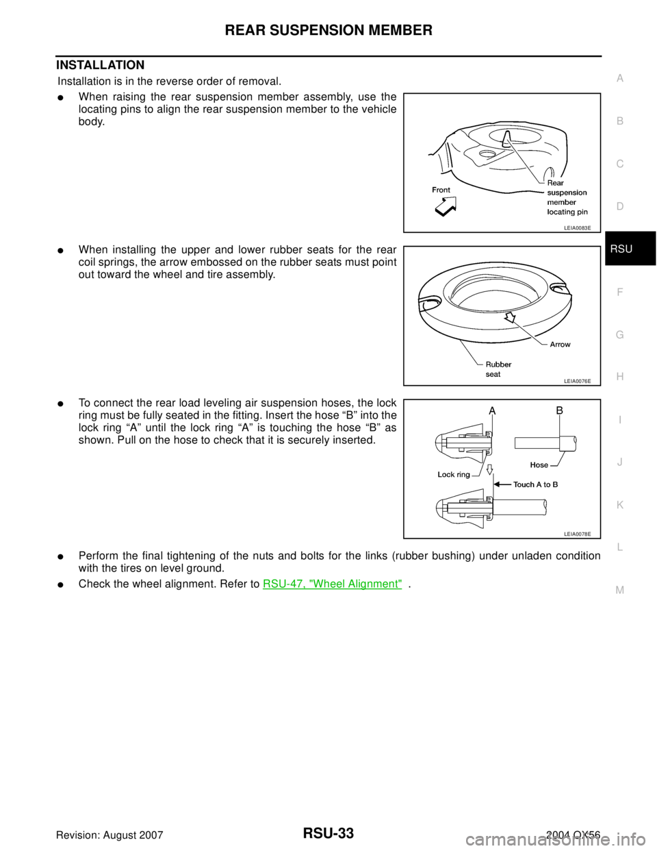
INSTALLATION
Installation is in the reverse order of removal.
�When raising the rear suspension member assembly, use the
locating pins to align the rear suspension member to the vehicle
body.
�When installing the upper and lower rubber seats for the rear
coil springs, the arrow embossed on the rubber seats must point
out toward the wheel and tire assembly.
�To connect the rear load leveling air suspension hoses, the lock
ring must be fully seated in the fitting. Insert the hose “B” into the
lock ring “A” until the lock ring “A” is touching the hose “B” as
shown. Pull on the hose to check that it is securely inserted.
�Perform the final tightening of the nuts and bolts for the links (rubber bushing) under unladen condition
with the tires on level ground.
�Check the wheel alignment. Refer to RSU-47, "Wheel Alignment" .
LEIA0083E
LEIA0076E
LEIA0078E
Page 2899 of 3371
RSU-40
REAR LOWER LINK & COIL SPRING
Revision: August 20072004 QX56
8. Remove the rear lower link adjusting bolt and nut from the rear
suspension member using power tool, then remove the rear
lower link.
INSPECTION AFTER REMOVAL
Check the coil spring and rubber seats for deformation, cracks, or other damage and replace if necessary.
INSTALLATION
Installation is in the reverse order of removal.
�Tighten the nuts and bolts to specification. Refer to RSU-25, "Components" .
�When installing the upper and lower rubber seats for the rear
coil springs, the arrow embossed on the rubber seats must point
out toward the wheel and tire assembly.
�After installing the rear lower link and coil spring, check the
wheel alignment and adjust if necessary. Refer to RSU-27,
"Wheel Alignment Inspection" .
LEIA0009E
LEIA0076E