Page 1862 of 3371
OVER FENDER
EI-21
C
D
E
F
G
H
J
K
L
MA
B
EI
Revision: August 20072004 QX56
OVER FENDERPFP:63810
Removal and InstallationEIS002ZX
REMOVAL
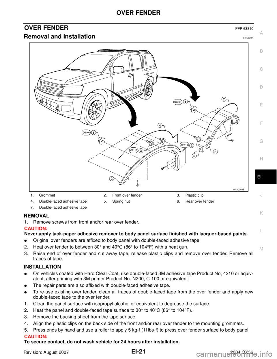
1. Remove screws from front and/or rear over fender.
CAUTION:
Never apply tack-paper adhesive remover to body panel surface finished with lacquer-based paints.
�Original over fenders are affixed to body panel with double-faced adhesive tape.
2. Heat over fender to between 30° and 40°C (86° to 104°F) with a heat gun.
3. Raise end of over fender and cut away tape, release plastic clips and remove over fender. Remove all
traces of tape.
INSTALLATION
�On vehicles coated with Hard Clear Coat, use double-faced 3M adhesive tape Product No, 4210 or equiv-
alent, after priming with 3M primer Product No. N200, C-100 or equivalent.
�The repair parts are also affixed with double-faced adhesive tape.
�To re-use existing over fender, clean all traces of double-faced tape from the over fender and apply new
double-faced tape to the over fender.
1. Clean the panel surface with isopropyl alcohol or equivalent to degrease the surface.
2. Heat the panel and double-faced tape surface to 30° to 40°C (86° to 104°F).
3. Remove the backing sheet from the tape surface.
4. Align the plastic clips on the back side of the front and/or rear over fender to the mounting grommets.
5. Press ends by hand and use a roller to apply 5 kg-f (11lbs-f) to press over fender surface to body panel.
CAUTION:
To secure contact, do not wash vehicle for 24 hours after installation.
1. Grommet 2. Front over fender 3. Plastic clip
4. Double-faced adhesive tape 5. Spring nut 6. Rear over fender
7. Double-faced adhesive tape
WIIA0268E
Page 1863 of 3371
EI-22
OVER FENDER
Revision: August 20072004 QX56
6. Secure front and/or rear over fender with screws.
Page 1871 of 3371
EI-30
SIDE GUARD MOLDING
Revision: August 20072004 QX56
2. Heat the panel and double-faced adhesive tape surface to 30° to 40°C (86° to 104°F).
3. Remove the backing sheet from the double-faced adhesive tape surface.
�Align the plastic clips into the holes in the outer door.
�Continue aligning the plastic clips into their corresponding holes in the outer door during installation.
4. Press ends by hand and use a roller to apply 5 kg-f (11 lbs-f) to press double-faced adhesive tape surface
on side guard molding to door surface.
�Apply even pressure along double-faced adhesive tape surface on side guard molding to insure proper
wet out.
CAUTION:
To secure contact of double-faced adhesive tape, do not wash vehicle for 24 hours after installation.
Page 1896 of 3371
DRIVE BELTS
EM-13
C
D
E
F
G
H
I
J
K
L
MA
EM
Revision: August 20072004 QX56
INSTALLATION
Installation is in the reverse order of removal.
CAUTION:
Make sure belt is securely installed around all pulleys.
�Rotate the crankshaft pulley several turns clockwise to equalize belt tension between pulleys.
�Make sure belt tension is within the allowable working range, using the indicator notch on the auto ten-
sioner. Refer to EM-12, "
Checking Drive Belts" .
Drive Belt Auto Tensioner and Idler PulleyEBS00ILD
REMOVAL
1. Remove the air duct and resonator assembly. Refer to EM-14, "Removal and Installation" .
2. Remove the drive belt. Refer to EM-12, "
Checking Drive Belts" .
3. Remove the auto tensioner and idler pulley using power tool.
INSTALLATION
Installation is in the reverse order of removal.
WBIA0607E
1. Auto tensioner 2. Idler pulley
Page 1914 of 3371
FUEL INJECTOR AND FUEL TUBE
EM-31
C
D
E
F
G
H
I
J
K
L
MA
EM
Revision: August 20072004 QX56
�Handle O-ring with bare hands. Never wear gloves.
�Lubricate O-ring with new engine oil.
�Do not clean O-ring with solvent.
�Make sure that O-ring and its mating part are free of foreign material.
�When installing O-ring, be careful not to scratch it with tool or fingernails. Also be careful not to
twist or stretch O-ring. If O-ring was stretched while it was being attached, do not insert it
quickly into fuel tube.
�Insert O-ring straight into fuel tube. Do not angle or twist it.
3. Install the fuel injector to the fuel tube using the following steps.
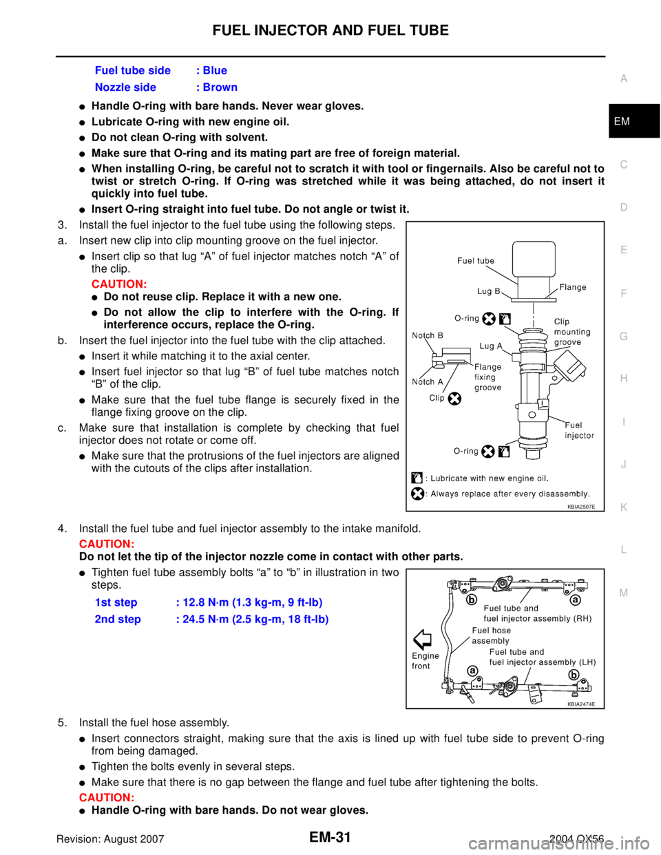
a. Insert new clip into clip mounting groove on the fuel injector.
�Insert clip so that lug “A” of fuel injector matches notch “A” of
the clip.
CAUTION:
�Do not reuse clip. Replace it with a new one.
�Do not allow the clip to interfere with the O-ring. If
interference occurs, replace the O-ring.
b. Insert the fuel injector into the fuel tube with the clip attached.
�Insert it while matching it to the axial center.
�Insert fuel injector so that lug “B” of fuel tube matches notch
“B” of the clip.
�Make sure that the fuel tube flange is securely fixed in the
flange fixing groove on the clip.
c. Make sure that installation is complete by checking that fuel
injector does not rotate or come off.
�Make sure that the protrusions of the fuel injectors are aligned
with the cutouts of the clips after installation.
4. Install the fuel tube and fuel injector assembly to the intake manifold.
CAUTION:
Do not let the tip of the injector nozzle come in contact with other parts.
�Tighten fuel tube assembly bolts “a” to “b” in illustration in two
steps.
5. Install the fuel hose assembly.
�Insert connectors straight, making sure that the axis is lined up with fuel tube side to prevent O-ring
from being damaged.
�Tighten the bolts evenly in several steps.
�Make sure that there is no gap between the flange and fuel tube after tightening the bolts.
CAUTION:
�Handle O-ring with bare hands. Do not wear gloves.Fuel tube side : Blue
Nozzle side : Brown
KBIA2507E
1st step : 12.8 N·m (1.3 kg-m, 9 ft-lb)
2nd step : 24.5 N·m (2.5 kg-m, 18 ft-lb)
KBIA2474E
Page 1921 of 3371
EM-38Revision: August 2007
TIMING CHAIN
2004 QX56
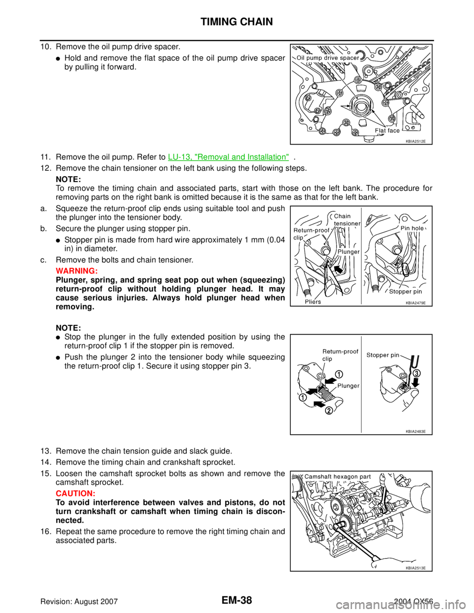
10. Remove the oil pump drive spacer.
�Hold and remove the flat space of the oil pump drive spacer
by pulling it forward.
11. Remove the oil pump. Refer to LU-13, "
Removal and Installation" .
12. Remove the chain tensioner on the left bank using the following steps.
NOTE:
To remove the timing chain and associated parts, start with those on the left bank. The procedure for
removing parts on the right bank is omitted because it is the same as that for the left bank.
a. Squeeze the return-proof clip ends using suitable tool and push
the plunger into the tensioner body.
b. Secure the plunger using stopper pin.
�Stopper pin is made from hard wire approximately 1 mm (0.04
in) in diameter.
c. Remove the bolts and chain tensioner.
WAR NIN G:
Plunger, spring, and spring seat pop out when (squeezing)
return-proof clip without holding plunger head. It may
cause serious injuries. Always hold plunger head when
removing.
NOTE:
�Stop the plunger in the fully extended position by using the
return-proof clip 1 if the stopper pin is removed.
�Push the plunger 2 into the tensioner body while squeezing
the return-proof clip 1. Secure it using stopper pin 3.
13. Remove the chain tension guide and slack guide.
14. Remove the timing chain and crankshaft sprocket.
15. Loosen the camshaft sprocket bolts as shown and remove the
camshaft sprocket.
CAUTION:
To avoid interference between valves and pistons, do not
turn crankshaft or camshaft when timing chain is discon-
nected.
16. Repeat the same procedure to remove the right timing chain and
associated parts.
KBIA2512E
KBIA2479E
KBIA2483E
KBIA2513E
Page 1927 of 3371
EM-44Revision: August 2007
CAMSHAFT
2004 QX56
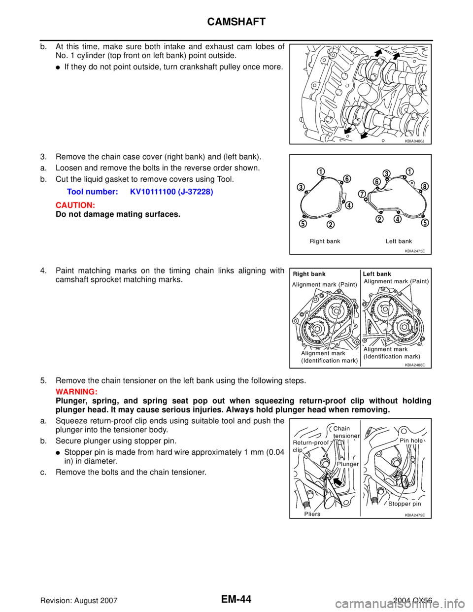
b. At this time, make sure both intake and exhaust cam lobes of
No. 1 cylinder (top front on left bank) point outside.
�If they do not point outside, turn crankshaft pulley once more.
3. Remove the chain case cover (right bank) and (left bank).
a. Loosen and remove the bolts in the reverse order shown.
b. Cut the liquid gasket to remove covers using Tool.
CAUTION:
Do not damage mating surfaces.
4. Paint matching marks on the timing chain links aligning with
camshaft sprocket matching marks.
5. Remove the chain tensioner on the left bank using the following steps.
WAR NIN G:
Plunger, spring, and spring seat pop out when squeezing return-proof clip without holding
plunger head. It may cause serious injuries. Always hold plunger head when removing.
a. Squeeze return-proof clip ends using suitable tool and push the
plunger into the tensioner body.
b. Secure plunger using stopper pin.
�Stopper pin is made from hard wire approximately 1 mm (0.04
in) in diameter.
c. Remove the bolts and the chain tensioner.
KBIA0400J
Tool number: KV10111100 (J-37228)
KBIA2475E
KBIA2488E
KBIA2479E
Page 1928 of 3371
CAMSHAFT
EM-45
C
D
E
F
G
H
I
J
K
L
MA
EM
Revision: August 20072004 QX56
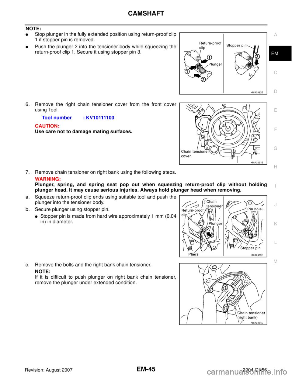
NOTE:
�Stop plunger in the fully extended position using return-proof clip
1 if stopper pin is removed.
�Push the plunger 2 into the tensioner body while squeezing the
return-proof clip 1. Secure it using stopper pin 3.
6. Remove the right chain tensioner cover from the front cover
using Tool.
CAUTION:
Use care not to damage mating surfaces.
7. Remove chain tensioner on right bank using the following steps.
WAR NIN G:
Plunger, spring, and spring seat pop out when squeezing return-proof clip without holding
plunger head. It may cause serious injuries. Always hold plunger head when removing.
a. Squeeze return-proof clip ends using suitable tool and push the
plunger into the tensioner body.
b. Secure plunger using stopper pin.
�Stopper pin is made from hard wire approximately 1 mm (0.04
in) in diameter.
c. Remove the bolts and the right bank chain tensioner.
NOTE:
If it is difficult to push plunger on right bank chain tensioner,
remove the plunger under extended condition.
KBIA2483E
Tool number : KV10111100
KBIA2521E
KBIA2479E
KBIA2484E