Page 1481 of 3371
EC-290Revision: August 2007
DTC P0444, P0445 EVAP CANISTER PURGE VOLUME CONTROL SOLENOID
VALVE
2004 QX56
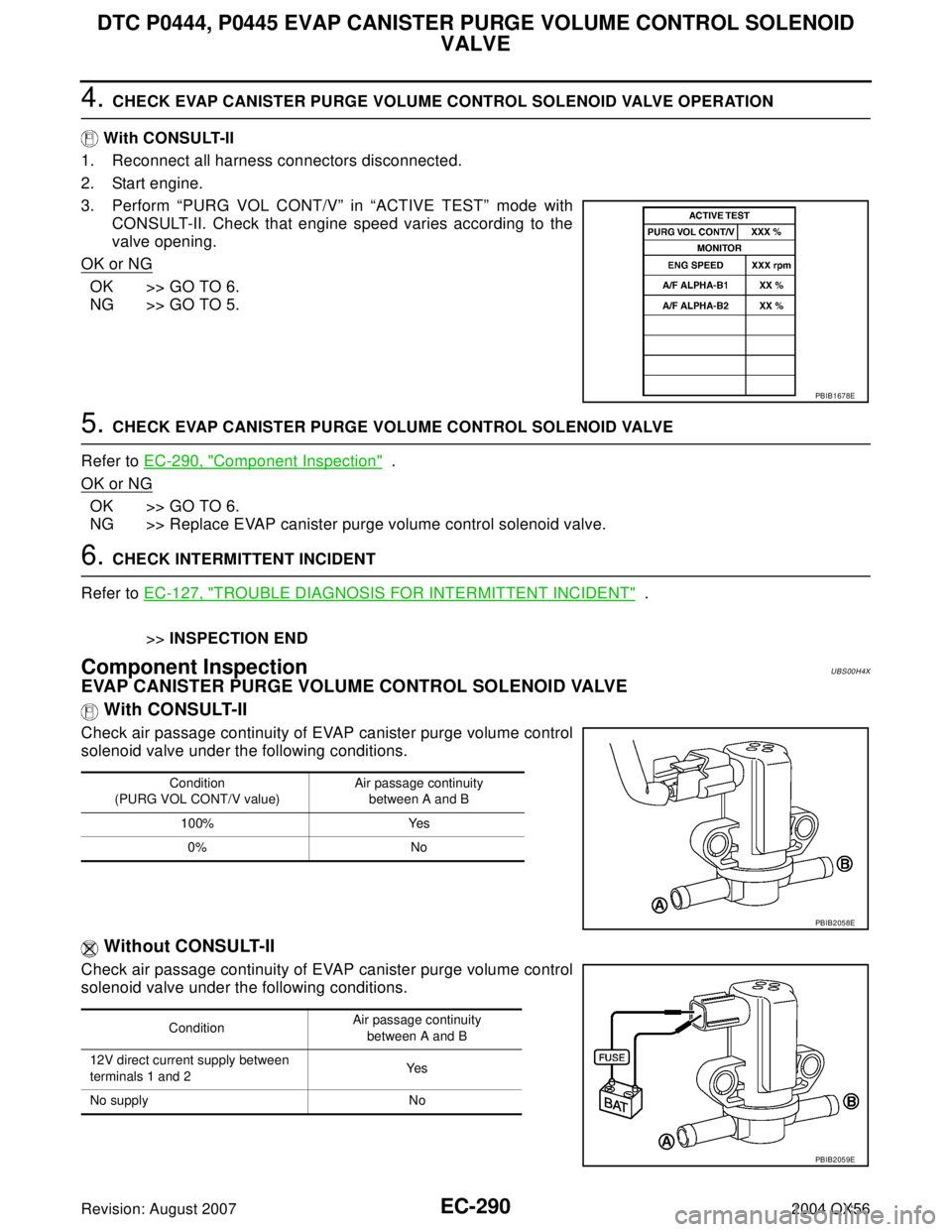
4. CHECK EVAP CANISTER PURGE VOLUME CONTROL SOLENOID VALVE OPERATION
With CONSULT-II
1. Reconnect all harness connectors disconnected.
2. Start engine.
3. Perform “PURG VOL CONT/V” in “ACTIVE TEST” mode with
CONSULT-II. Check that engine speed varies according to the
valve opening.
OK or NG
OK >> GO TO 6.
NG >> GO TO 5.
5. CHECK EVAP CANISTER PURGE VOLUME CONTROL SOLENOID VALVE
Refer to EC-290, "
Component Inspection" .
OK or NG
OK >> GO TO 6.
NG >> Replace EVAP canister purge volume control solenoid valve.
6. CHECK INTERMITTENT INCIDENT
Refer to EC-127, "
TROUBLE DIAGNOSIS FOR INTERMITTENT INCIDENT" .
>>INSPECTION END
Component InspectionUBS00H4X
EVAP CANISTER PURGE VOLUME CONTROL SOLENOID VALVE
With CONSULT-II
Check air passage continuity of EVAP canister purge volume control
solenoid valve under the following conditions.
Without CONSULT-II
Check air passage continuity of EVAP canister purge volume control
solenoid valve under the following conditions.
PBIB1678E
Condition
(PURG VOL CONT/V value)Air passage continuity
between A and B
100% Yes
0% No
PBIB2058E
ConditionAir passage continuity
between A and B
12V direct current supply between
terminals 1 and 2Ye s
No supply No
PBIB2059E
Page 1484 of 3371
DTC P0447 EVAP CANISTER VENT CONTROL VALVE
EC-293
C
D
E
F
G
H
I
J
K
L
MA
EC
Revision: August 20072004 QX56
DTC Confirmation ProcedureUBS00H52
NOTE:
If DTC Confirmation Procedure has been previously conducted, always turn ignition switch OFF and wait at
least 10 seconds before conducting the next test.
TESTING CONDITION:
Before performing the following procedure, confirm battery voltage is more than 11V at idle.
WITH CONSULT-II
1. Turn ignition switch ON.
2. Select “DATA MONITOR” mode with CONSULT-II.
3. Start engine and wait at least 8 seconds.
4. If 1st trip DTC is detected, go to EC-295, "
Diagnostic Procedure"
.
WITH GST
Follow the procedure “WITH CONSULT-II” above.
SEF 0 58 Y
Page 1488 of 3371
DTC P0447 EVAP CANISTER VENT CONTROL VALVE
EC-297
C
D
E
F
G
H
I
J
K
L
MA
EC
Revision: August 20072004 QX56
6. DETECT MALFUNCTIONING PART
Check the following.
�Harness connectors E41, C1
�Harness for open or short between EVAP canister vent control valve and ECM
>> Repair open circuit or short to ground or short to power in harness or connectors.
7. CHECK RUBBER TUBE FOR CLOGGING
1. Disconnect rubber tube connected to EVAP canister vent control valve.
2. Check the rubber tube for clogging.
OK or NG
OK >> GO TO 8.
NG >> Clean the rubber tube using an air blower.
8. CHECK EVAP CANISTER VENT CONTROL VALVE
Refer to EC-297, "
Component Inspection" .
OK or NG
OK >> GO TO 9.
NG >> Replace EVAP canister vent control valve.
9. CHECK INTERMITTENT INCIDENT
Refer to EC-127, "
TROUBLE DIAGNOSIS FOR INTERMITTENT INCIDENT" .
>>INSPECTION END
Component InspectionUBS00H55
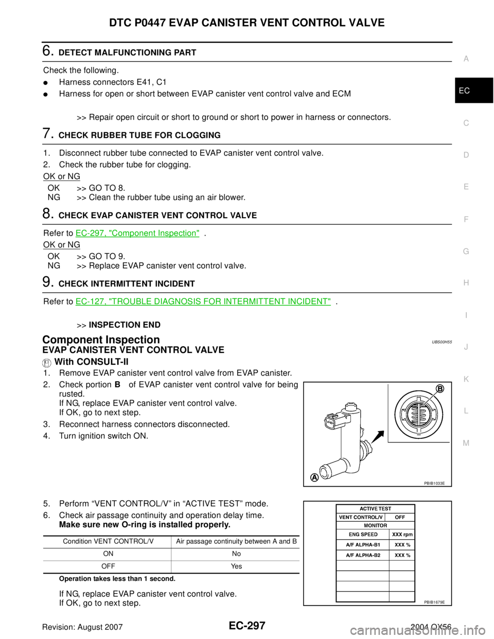
EVAP CANISTER VENT CONTROL VALVE
With CONSULT-II
1. Remove EVAP canister vent control valve from EVAP canister.
2. Check portion B of EVAP canister vent control valve for being
rusted.
If NG, replace EVAP canister vent control valve.
If OK, go to next step.
3. Reconnect harness connectors disconnected.
4. Turn ignition switch ON.
5. Perform “VENT CONTROL/V” in “ACTIVE TEST” mode.
6. Check air passage continuity and operation delay time.
Make sure new O-ring is installed properly.
Operation takes less than 1 second.
If NG, replace EVAP canister vent control valve.
If OK, go to next step.
PBIB1033E
Condition VENT CONTROL/V Air passage continuity between A and B
ON No
OFF Yes
PBIB1679E
Page 1491 of 3371
EC-300Revision: August 2007
DTC P0451 EVAP CONTROL SYSTEM PRESSURE SENSOR
2004 QX56
DTC Confirmation ProcedureUBS00H59
NOTE:
If DTC Confirmation Procedure has been previously conducted, always turn ignition switch OFF and wait at
least 10 seconds before conducting the next test.
WITH CONSULT-II
1. Turn ignition switch OFF and wait at least 10 seconds.
2. Turn ignition switch ON and select “DATA MONITOR” mode with
CONSULT-II.
3. Start engine and wait at least 40 seconds.
NOTE:
Do not depress accelerator pedal even slightly.
If 1st trip DTC is detected, go to EC-300, "
Diagnostic Procedure"
.
WITH GST
Follow the procedure “WITH CONSULT-II” above.
Diagnostic ProcedureUBS00H5A
1. CHECK GROUND CONNECTIONS
1. Turn ignition switch OFF.
2. Loosen and retighten three ground screws on the body.
Refer to EC-133, "
Ground Inspection" .
OK or NG
OK >> GO TO 2.
NG >> Repair or replace ground connections.
SEF 1 94 Y
BBIA0354E
Page 1494 of 3371

DTC P0452 EVAP CONTROL SYSTEM PRESSURE SENSOR
EC-303
C
D
E
F
G
H
I
J
K
L
MA
EC
Revision: August 20072004 QX56
DTC Confirmation ProcedureUBS00H5F
NOTE:
If DTC Confirmation Procedure has been previously conducted, always turn ignition switch OFF and wait at
least 10 seconds before conducting the next test.
TESTING CONDITION:
Always perform test at a temperature of 5°C (41°F) or more.
WITH CONSULT-II
1. Start engine and warm it up to normal operating temperature.
2. Turn ignition switch OFF and wait at least 10 seconds.
3. Turn ignition switch ON.
4. Select “DATA MONITOR” mode with CONSULT-II.
5. Make sure that “FUEL T/TMP SE” is more than 0°C (32°F).
6. Start engine and wait at least 20 seconds.
If 1st trip DTC is detected, go to EC-305, "
Diagnostic Procedure"
.
WITH GST
1. Start engine and warm it up to normal operating temperature.
2. Check that voltage between ECM terminal 107 (Fuel tank tem-
perature sensor signal) and ground is less than 4.2V.
3. Turn ignition switch OFF and wait at least 10 seconds.
4. Start engine and wait at least 20 seconds.
5. Select MODE 7 with GST.
If 1st trip DTC is detected, go to EC-305, "
Diagnostic Procedure"
.
SEF 1 94 Y
PB I B 111 0E
Page 1500 of 3371
DTC P0453 EVAP CONTROL SYSTEM PRESSURE SENSOR
EC-309
C
D
E
F
G
H
I
J
K
L
MA
EC
Revision: August 20072004 QX56
DTC Confirmation ProcedureUBS00H5M
NOTE:
If DTC Confirmation Procedure has been previously conducted, always turn ignition switch OFF and wait at
least 10 seconds before conducting the next test.
TESTING CONDITION:
Always perform test at a temperature of 5°C (41°F) or more.
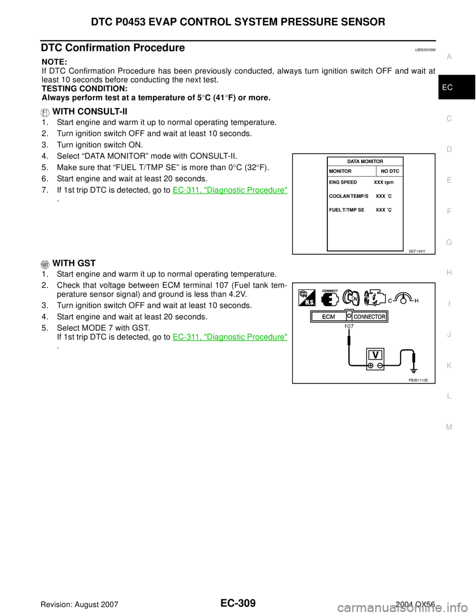
WITH CONSULT-II
1. Start engine and warm it up to normal operating temperature.
2. Turn ignition switch OFF and wait at least 10 seconds.
3. Turn ignition switch ON.
4. Select “DATA MONITOR” mode with CONSULT-II.
5. Make sure that “FUEL T/TMP SE” is more than 0°C (32°F).
6. Start engine and wait at least 20 seconds.
7. If 1st trip DTC is detected, go to EC-311, "
Diagnostic Procedure"
.
WITH GST
1. Start engine and warm it up to normal operating temperature.
2. Check that voltage between ECM terminal 107 (Fuel tank tem-
perature sensor signal) and ground is less than 4.2V.
3. Turn ignition switch OFF and wait at least 10 seconds.
4. Start engine and wait at least 20 seconds.
5. Select MODE 7 with GST.
If 1st trip DTC is detected, go to EC-311, "
Diagnostic Procedure"
.
SEF 1 94 Y
PB I B 111 0E
Page 1508 of 3371
DTC P0455 EVAP CONTROL SYSTEM
EC-317
C
D
E
F
G
H
I
J
K
L
MA
EC
Revision: August 20072004 QX56
DTC Confirmation ProcedureUBS00H5R
CAUTION:
Never remove fuel filler cap during the DTC Confirmation Procedure.
NOTE:
�Make sure that EVAP hoses are connected to EVAP canister purge volume control solenoid valve
properly.
�If DTC Confirmation Procedure has been previously conducted, always turn ignition switch OFF and wait
at least 10 seconds before conducting the next test.
TESTING CONDITION:
�Perform “DTC WORK SUPPORT” when the fuel level is between 1/4 and 3/4 full, and vehicle is
placed on flat level surface.
�Open engine hood before conducting the following procedures.
WITH CONSULT-II
1. Tighten fuel filler cap securely until ratcheting sound is heard.
2. Turn ignition switch ON.
3. Turn ignition switch OFF and wait at least 10 seconds.
4. Turn ignition switch ON and select “DATA MONITOR” mode with CONSULT-II.
5. Make sure that the following conditions are met.
COOLAN TEMP/S: 0 - 70°C (32 - 158°F)
INT/A TEMP SE: 0 - 60°C (32 - 140°F)
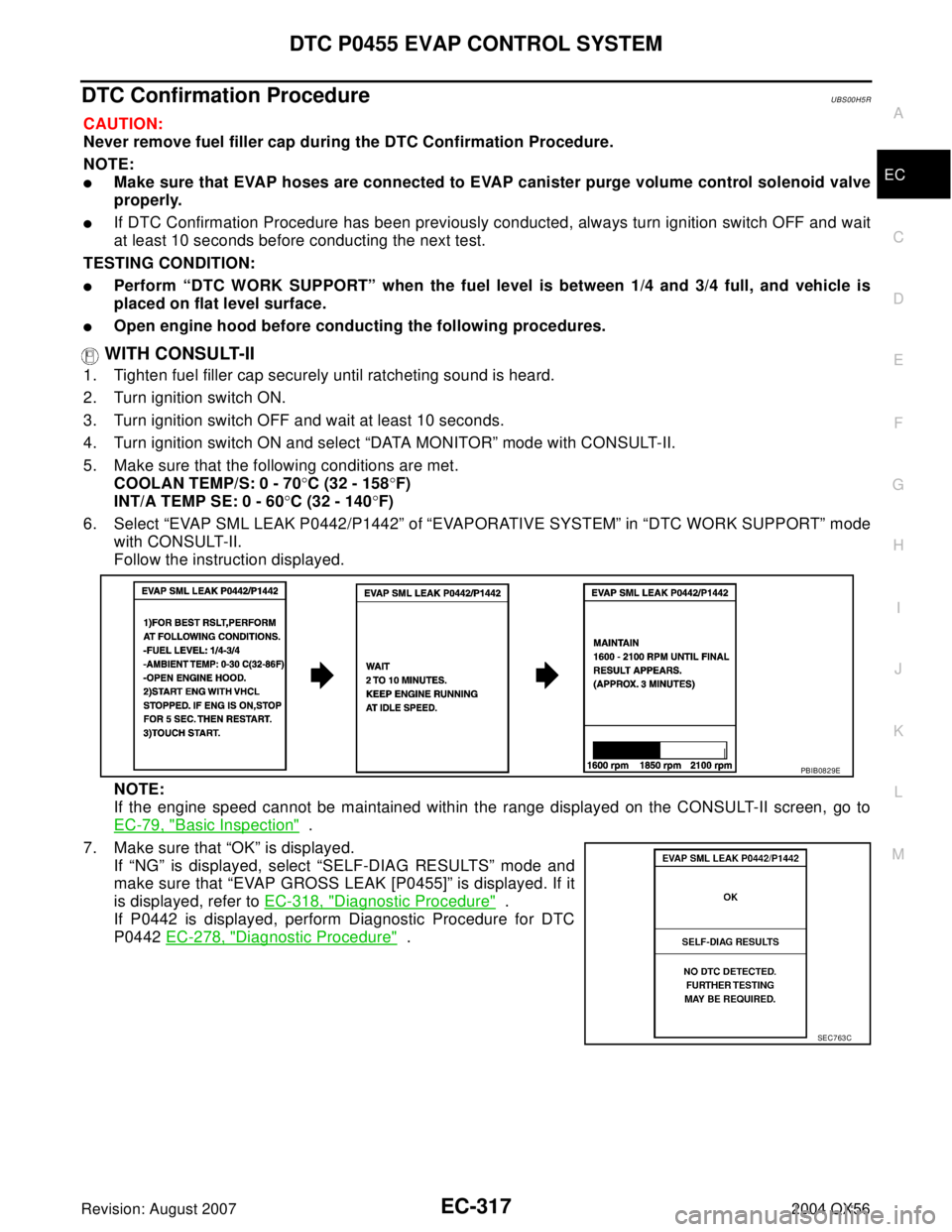
6. Select “EVAP SML LEAK P0442/P1442” of “EVAPORATIVE SYSTEM” in “DTC WORK SUPPORT” mode
with CONSULT-II.
Follow the instruction displayed.
NOTE:
If the engine speed cannot be maintained within the range displayed on the CONSULT-II screen, go to
EC-79, "
Basic Inspection" .
7. Make sure that “OK” is displayed.
If “NG” is displayed, select “SELF-DIAG RESULTS” mode and
make sure that “EVAP GROSS LEAK [P0455]” is displayed. If it
is displayed, refer to EC-318, "
Diagnostic Procedure" .
If P0442 is displayed, perform Diagnostic Procedure for DTC
P0442 EC-278, "
Diagnostic Procedure" .
PBIB0829E
SEC7 63 C
Page 1509 of 3371
EC-318Revision: August 2007
DTC P0455 EVAP CONTROL SYSTEM
2004 QX56
WITH GST
NOTE:
Be sure to read the explanation of EC-59, "
Driving Pattern" before driving vehicle.
1. Start engine.
2. Drive vehicle according to EC-59, "
Driving Pattern" .
3. Stop vehicle.
4. Turn ignition switch OFF, wait at least 10 seconds and then turn ON.
5. Select MODE 7 with GST.
�If P0455 is displayed on the screen, go to EC-318, "Diagnostic Procedure" .
�If P0442 is displayed on the screen, go to EC-278, "Diagnostic Procedure" .
�If P0441 is displayed on the screen, go to EC-273, "Diagnostic Procedure" .
Diagnostic ProcedureUBS00H5S
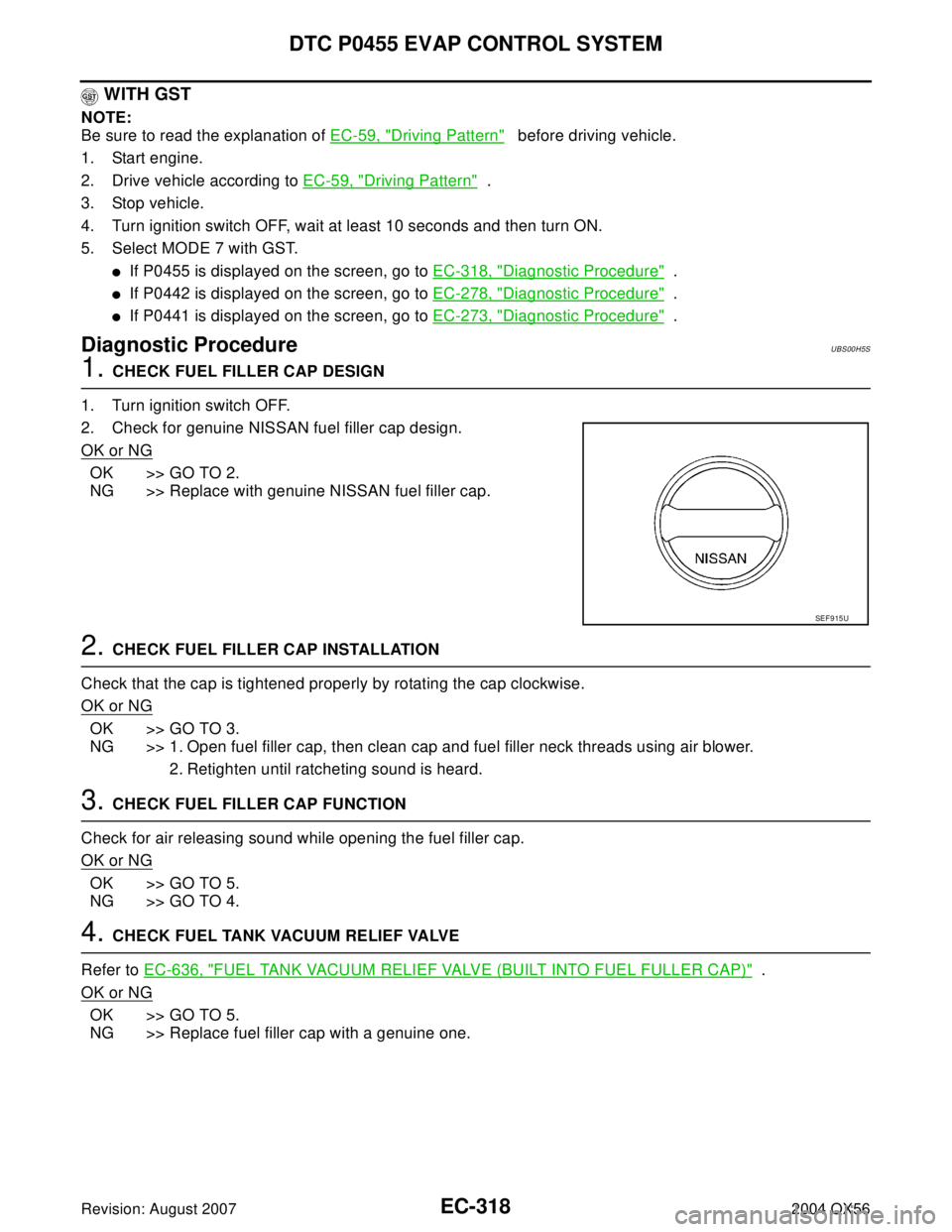
1. CHECK FUEL FILLER CAP DESIGN
1. Turn ignition switch OFF.
2. Check for genuine NISSAN fuel filler cap design.
OK or NG
OK >> GO TO 2.
NG >> Replace with genuine NISSAN fuel filler cap.
2. CHECK FUEL FILLER CAP INSTALLATION
Check that the cap is tightened properly by rotating the cap clockwise.
OK or NG
OK >> GO TO 3.
NG >> 1. Open fuel filler cap, then clean cap and fuel filler neck threads using air blower.
2. Retighten until ratcheting sound is heard.
3. CHECK FUEL FILLER CAP FUNCTION
Check for air releasing sound while opening the fuel filler cap.
OK or NG
OK >> GO TO 5.
NG >> GO TO 4.
4. CHECK FUEL TANK VACUUM RELIEF VALVE
Refer to EC-636, "
FUEL TANK VACUUM RELIEF VALVE (BUILT INTO FUEL FULLER CAP)" .
OK or NG
OK >> GO TO 5.
NG >> Replace fuel filler cap with a genuine one.
SEF 9 15 U