Page 2767 of 3371

PS-16
POWER STEERING GEAR AND LINKAGE
Revision: August 20072004 QX56
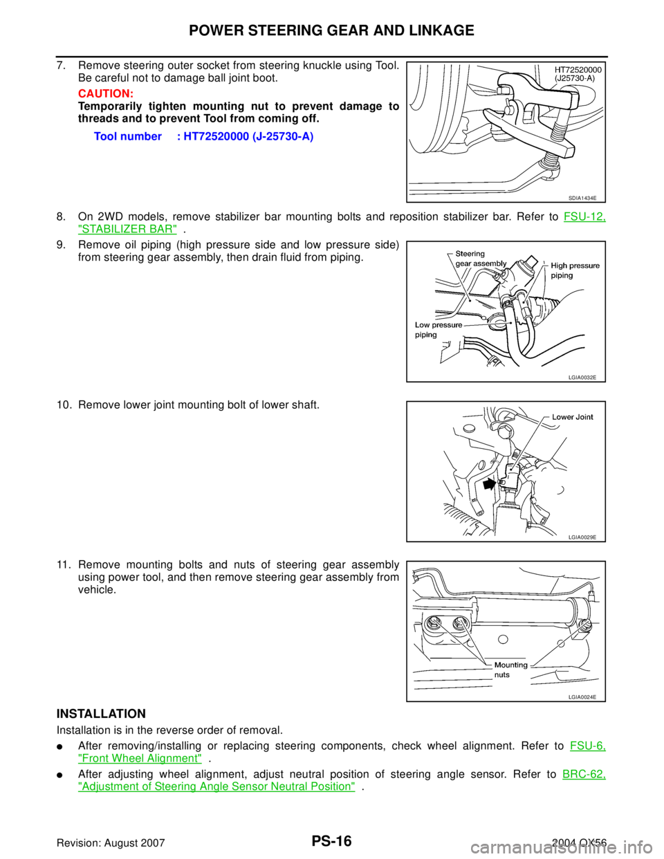
7. Remove steering outer socket from steering knuckle using Tool.
Be careful not to damage ball joint boot.
CAUTION:
Temporarily tighten mounting nut to prevent damage to
threads and to prevent Tool from coming off.
8. On 2WD models, remove stabilizer bar mounting bolts and reposition stabilizer bar. Refer to FSU-12,
"STABILIZER BAR" .
9. Remove oil piping (high pressure side and low pressure side)
from steering gear assembly, then drain fluid from piping.
10. Remove lower joint mounting bolt of lower shaft.
11. Remove mounting bolts and nuts of steering gear assembly
using power tool, and then remove steering gear assembly from
vehicle.
INSTALLATION
Installation is in the reverse order of removal.
�After removing/installing or replacing steering components, check wheel alignment. Refer to FSU-6,
"Front Wheel Alignment" .
�After adjusting wheel alignment, adjust neutral position of steering angle sensor. Refer to BRC-62,
"Adjustment of Steering Angle Sensor Neutral Position" . Tool number : HT72520000 (J-25730-A)
SDIA1434E
LGIA0032E
LGIA0029E
LGIA0024E
Page 2886 of 3371

REAR SUSPENSION ASSEMBLY
RSU-27
C
D
F
G
H
I
J
K
L
MA
B
RSU
Revision: August 20072004 QX56
Wheel Alignment InspectionEES0011H
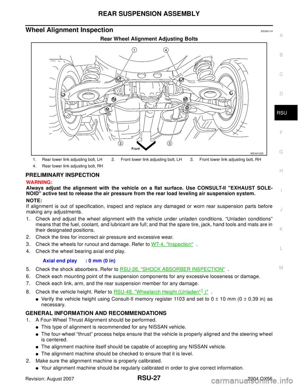
Rear Wheel Alignment Adjusting Bolts
PRELIMINARY INSPECTION
WA RN ING:
Always adjust the alignment with the vehicle on a flat surface. Use CONSULT-II "EXHAUST SOLE-
NOID" active test to release the air pressure from the rear load leveling air suspension system.
NOTE:
If alignment is out of specification, inspect and replace any damaged or worn rear suspension parts before
making any adjustments.
1. Check and adjust the wheel alignment with the vehicle under unladen conditions. “Unladen conditions”
means that the fuel, coolant, and lubricant are full; and that the spare tire, jack, hand tools and mats are in
their designated positions.
2. Check the tires for incorrect air pressure and excessive wear.
3. Check the wheels for runout and damage. Refer to WT-4, "
Inspection" .
4. Check the wheel bearing axial end play.
5. Check the shock absorbers. Refer to RSU-26, "
SHOCK ABSORBER INSPECTION" .
6. Check each mounting point of the suspension components for any excessive looseness or damage.
7. Check each link, arm, and the rear suspension member for any damage.
8. Check the vehicle height. Refer to RSU-48, "
Wheelarch Height (Unladen*1 )" .
�Verify the vehicle height using Consult-II memory register 1103 and set to 0 ± 10 mm (0 ± 0.39 in) as
necessary.
GENERAL INFORMATION AND RECOMMENDATIONS
1. A Four-Wheel Thrust Alignment should be performed.
�This type of alignment is recommended for any NISSAN vehicle.
�The four-wheel “thrust” process helps ensure that the vehicle is properly aligned and the steering wheel
is centered.
�The alignment machine itself should be capable of accepting any NISSAN vehicle.
�The alignment machine should be checked to ensure that it is level.
2. Make sure the alignment machine is properly calibrated.
�Your alignment machine should be regularly calibrated in order to give correct information.
WEIA0102E
1. Rear lower link adjusting bolt, LH 2. Front lower link adjusting bolt, LH 3. Front lower link adjusting bolt, RH
4. Rear lower link adjusting bolt, RH
Axial end play : 0 mm (0 in)
Page 2964 of 3371
AUTOMATIC DRIVE POSITIONER
SE-15
C
D
E
F
G
H
J
K
L
MA
B
SE
Revision: August 20072004 QX56
MEMORY OPERATION
Selecting the memorized position.
NOTE:
The front seat position and pedal adjustment functions (see the following table) operate simultaneously in the
order of priority.
*: In conjunction with sliding the seat, the door mirrors are positioned.
ENTRY OPERATION
When the seat is in the exiting position, the following operation moves the seat to the previous position before
the exiting operation.
EXITING OPERATION
At Entry/Exiting, the seat is automatically moved to the exiting position.
Priority Function Priority Function
1 Seat sliding, (door mirror LH/RH)* 4 Seat reclining
2 Pedal 5 Seat lifter-FR
3 Steering wheel 6 Seat lifter-RR
LIIA1477E
LIIA0855E
LIIA0856E
Page 3109 of 3371

SRS-48
SPIRAL CABLE
Revision: August 20072004 QX56
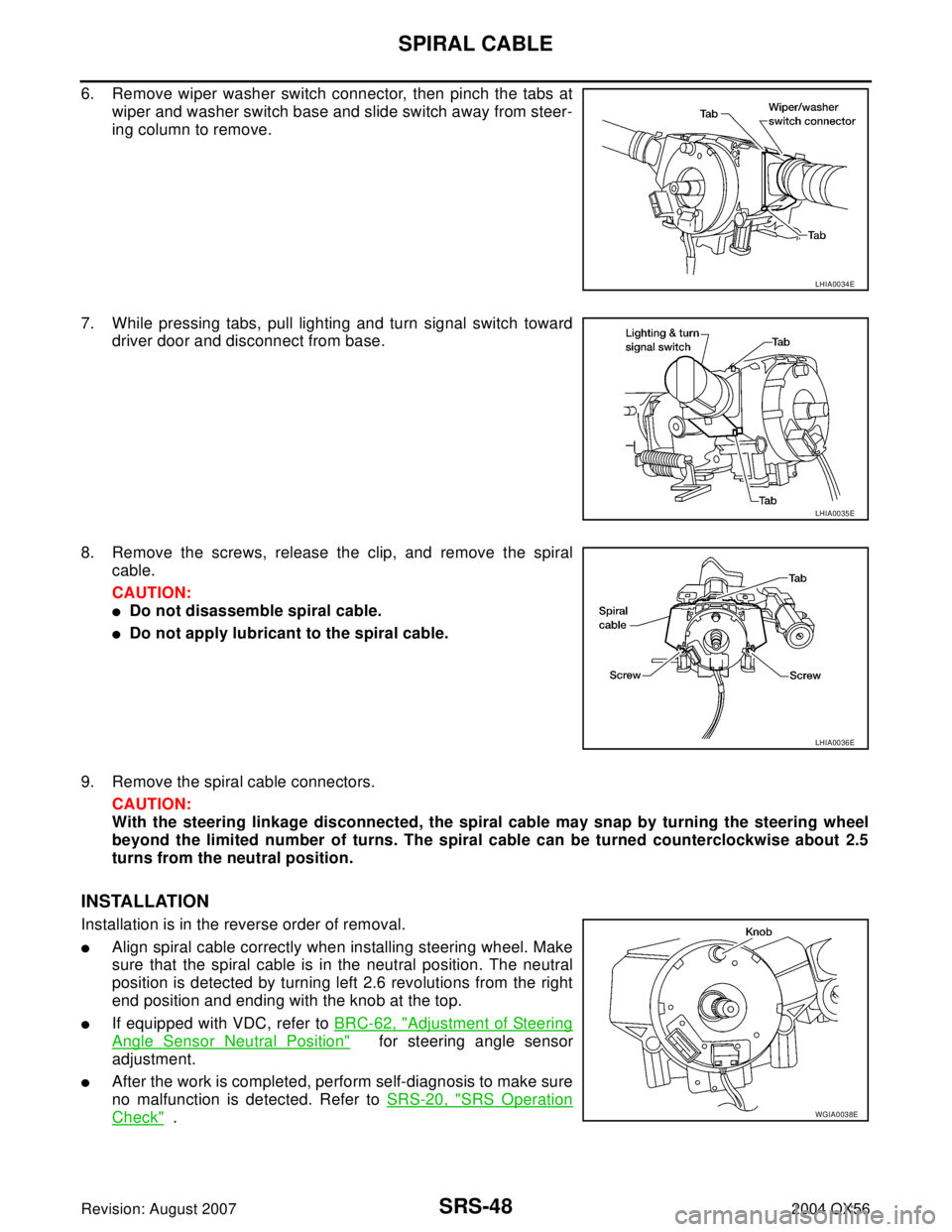
6. Remove wiper washer switch connector, then pinch the tabs at
wiper and washer switch base and slide switch away from steer-
ing column to remove.
7. While pressing tabs, pull lighting and turn signal switch toward
driver door and disconnect from base.
8. Remove the screws, release the clip, and remove the spiral
cable.
CAUTION:
�Do not disassemble spiral cable.
�Do not apply lubricant to the spiral cable.
9. Remove the spiral cable connectors.
CAUTION:
With the steering linkage disconnected, the spiral cable may snap by turning the steering wheel
beyond the limited number of turns. The spiral cable can be turned counterclockwise about 2.5
turns from the neutral position.
INSTALLATION
Installation is in the reverse order of removal.
�Align spiral cable correctly when installing steering wheel. Make
sure that the spiral cable is in the neutral position. The neutral
position is detected by turning left 2.6 revolutions from the right
end position and ending with the knob at the top.
�If equipped with VDC, refer to BRC-62, "Adjustment of Steering
Angle Sensor Neutral Position" for steering angle sensor
adjustment.
�After the work is completed, perform self-diagnosis to make sure
no malfunction is detected. Refer to SRS-20, "
SRS Operation
Check" .
LHIA0034E
LHIA0035E
LHIA0036E
WGIA0038E
Page 3311 of 3371
WT-32
REMOVAL AND INSTALLATION
Revision: August 20072004 QX56
3. Place wheel on turntable of tire machine. Ensure that transmitter
is 270 degrees from mounting/dismounting head.
NOTE:
Do not touch transmitter with mounting head.
4. Lubricate tire well, and install second side of tire as normal.
Ensure that tire does not rotate relative to rim.
5. Inflate tire and balance the wheel and tire assembly. Refer to
WT-5
.
6. Install wheel and tire assembly in appropriate wheel position on
vehicle.
NOTE:
If replacing transmitter, transmitter wake up operation must be performed. Refer to WT-15, "
Transmitter
Wake Up Operation" .
7. Adjust neutral position of steering angle sensor. Refer to BRC-62, "
Adjustment of Steering Angle Sensor
Neutral Position" .
SEIA0048E