Page 1009 of 3371
 when assembling.
1. Apply clean brake fluid to new piston seal and")
BR-30
REAR DISC BRAKE
Revision: August 20072004 QX56
ASSEMBLY
CAUTION:
Do not use NISSAN Rubber Grease (KRE00 00010, KRE00 00010 01) when assembling.
1. Apply clean brake fluid to new piston seal and insert in to
groove on cylinder body.
CAUTION:
Do not reuse piston seal.
2. Apply brake fluid to piston and to piston boot, then install piston
boot in to piston groove.
CAUTION:
Do not reuse piston boot.
3. Insert into cylinder body by hand and insert piston boot piston-side lip into piston groove.
CAUTION:
Press piston evenly and vary the pressing point to prevent cylinder body inner wall from being
rubbed.
4. Install sliding boots and sleeves to cylinder body.
DISC ROTOR INSPECTION
Visual Inspection
Check surface of disc rotor for uneven wear, cracks, and serious damage. If any non-standard condition is
detected, replace applicable part.
Runout Inspection
1. Using wheel nuts, install disc rotor to wheel hub. (2 or more positions.)
2. Inspect runout using a dial gauge. [Measured at 10 mm (0.39 in)
inside disk edge.]
NOTE:
Make sure that wheel bearing axial end play is within the specifi-
cation before measuring runout. Refer to RAX-5, "
WHEEL
BEARING INSPECTION" .
3. If runout is outside the limit, find the minimum runout point by
shifting mounting positions of disc rotor and wheel hub by one
hole.
4. If runout still out of specification, turn rotor with on-car brake
lathe.
WFIA0210E
WFIA0211E
Runout limit (on vehicle) : 0.05 mm (0.0020 in)
BRA0013D
Page 2004 of 3371

DRIVE SHAFT
FAX-7
C
E
F
G
H
I
J
K
L
MA
B
FA X
Revision: August 20072004 QX56
DRIVE SHAFTPFP:39100
Removal and InstallationEDS001B5
REMOVAL
1. Remove wheel and tire using power tool.
2. Remove engine under cover using power tool.
3. Remove wheel sensor harness from mount on knuckle.
CAUTION:
Do not pull on wheel sensor harness.
4. Without disassembling the hydraulic lines, remove brake caliper using power tool. Reposition it aside with
wire. Refer to BR-22, "
Removal and Installation of Brake Caliper and Disc Rotor" .
NOTE:
Avoid depressing brake pedal while brake caliper is removed.
5. Remove coil spring and shock absorber assembly using power tool. Refer to FSU-10, "
Removal and
Installation" .
6. Separate upper link ball joint stud from steering knuckle using
Tool.
�Support lower link with jack.
7. Remove cotter pin, then remove drive shaft nut.
8. Remove drive shaft mounting bolts from front final drive.
9. Remove drive shaft from wheel hub and bearing assembly.
CAUTION:
�When removing drive shaft, do not apply an excessive
angle to drive shaft joint. Also be careful not to exces-
sively extend slide joint.
INSPECTION AFTER REMOVAL
�Move joint up, down, left, right, and in axial direction. Check for any rough movement or significant loose-
ness.
�Check boot for cracks or other damage, and for grease leakage.
�If damaged, disassemble drive shaft to verify damage, and
repair or replace as necessary.
1. Cotter pin 2. Drive shaft nut 3. Drive shaft
LDIA0159E
Tool number : ST29020001 (J-24319-01)
LEIA0095E
RAA0030D
Page 2005 of 3371
FAX-8
DRIVE SHAFT
Revision: August 20072004 QX56
INSTALLATION
Installation is in the reverse order of removal.
�Tighten wheel nuts to specification. Refer to WT-6, "Rotation" .
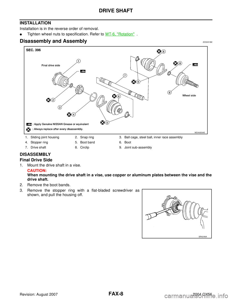
Disassembly and AssemblyEDS001B6
DISASSEMBLY
Final Drive Side
1. Mount the drive shaft in a vise.
CAUTION:
When mounting the drive shaft in a vise, use copper or aluminum plates between the vise and the
drive shaft.
2. Remove the boot bands.
3. Remove the stopper ring with a flat-bladed screwdriver as
shown, and pull the housing off.
1. Sliding joint housing 2. Snap ring 3. Ball cage, steel ball, inner race assembly
4. Stopper ring 5. Boot band 6. Boot
7. Drive shaft 8. Circlip 9. Joint sub-assembly
WDIA0054E
SRA2 49 A
Page 2006 of 3371

DRIVE SHAFT
FAX-9
C
E
F
G
H
I
J
K
L
MA
B
FA X
Revision: August 20072004 QX56
4. Remove the snap ring, then remove the ball cage, steel ball,
inner race assembly from the drive shaft.
5. Remove the boot from the drive shaft.
6. Remove any old grease on the housing using paper towels.
Wheel Side
1. Mount the drive shaft in a vise.
CAUTION:
When mounting the drive shaft in a vise, use copper or aluminum plates between the vise and the
drive shaft.
2. Remove the boot bands, then remove the boot from the joint sub-assembly.
3. Screw a suitable drive shaft puller 30 mm (1.18 in) or more into
the threaded part of the joint sub-assembly. Pull the joint sub-
assembly off of the drive shaft as shown.
NOTE:
Align the sliding hammer and drive shaft and remove the joint
sub-assembly by pulling directly.
CAUTION:
�If the joint sub-assembly cannot be removed after five or
more attempts, replace the drive shaft and joint sub-
assembly as a set.
4. Remove the boot from the drive shaft.
5. Remove the circlip from the drive shaft.
6. While rotating the ball cage, remove any old grease from the joint sub-assembly using paper towels.
INSPECTION AFTER DISASSEMBLY
Drive Shaft
�Replace the drive shaft if there is any runout, cracking, or other damage.
Joint Sub-assembly
�Check for any rough rotation or unusual axial looseness.
�Clean any foreign material from inside the joint sub-assembly.
�Check for any compression scars, cracks, or fractures.
CAUTION:
If any defective conditions are found in the joint sub-assembly components, replace the entire
joint sub-assembly.
Sliding Joint Side Housing
�Check for any compression scars, cracks, fractures, or unusual wear on the ball rolling surface.
�Check for any damage to the drive shaft screws.
�Check for any deformation of the boot installation components.
Ball Cage
�Check the sliding surface for any compression scars, cracks, or fractures.
SFA514A
SDIA0606E
Page 2007 of 3371

FAX-10
DRIVE SHAFT
Revision: August 20072004 QX56
Steel Ball
�Check for any compression scars, cracks, fractures, or unusual wear.
Inner Race
�Check the ball sliding surface for any compression scars, cracks, or fractures.
�Check for any damage to the serrated part.
CAUTION:
If any defective conditions are found, install a new housing, ball cage, steel ball, and inner race as
a set.
ASSEMBLY
Final Drive Side
1. Wrap the serrated part of the drive shaft with tape. Install the
boot band and boot to drive shaft.
NOTE:
Discard the old boot band and boot and use a new one for
assembly.
2. Remove the tape wound around the serrated part of the drive shaft.
3. Install the ball cage, steel ball, and inner race assembly on the
drive shaft, and secure them tightly using the snap ring.
NOTE:
Discard the old snap ring and use a new one for assembly.
4. Insert the specified quantity of Genuine NISSAN Grease or
equivalent, onto the housing (indicated by * marks), and install it
onto shaft. Refer to MA-10, "
RECOMMENDED FLUIDS AND
LUBRICANTS" .
5. Install the stopper ring onto the housing.
6. After installation, pull on the shaft to check engagement between the sliding joint and the stopper ring.
SFA80 0
SDIA11 25 E
Grease capacity : 130 − 150 g (4.58 − 5.29 oz)
RAC0678D
Page 2008 of 3371

as shown.
CAUTION:
If there is grease on boot mountin")
DRIVE SHAFT
FAX-11
C
E
F
G
H
I
J
K
L
MA
B
FA X
Revision: August 20072004 QX56
7. Install the boot securely into the grooves (indicated by * marks)
as shown.
CAUTION:
If there is grease on boot mounting surfaces (indicated by *
marks) of shaft and housing, boot may come off. Remove
all grease from surfaces.
8. Check that the boot installation length “L” is the length indicated
below. Insert a flat-tip screwdriver or similar tool into the big end
of the boot. Bleed air from the boot to prevent boot deformation.
CAUTION:
�The boot may break if the boot installation length is less than the specified value.
�Do not to touch the tip of the screwdriver to the inside of the boot.
9. Secure the big and small ends of the boot with the new boot
bands as shown.
NOTE:
Discard the old boot bands and use new ones for assembly.
10. After installing the sliding joint housing to the drive shaft, rotate the boot to check that the boot is posi-
tioned correctly. If the boot is not positioned correctly, reposition the boot and secure the boot using a new
boot band.
Wheel Side
1. Insert the Genuine NISSAN Grease or equivalent, into the joint
sub-assembly serration hole until the grease begins to ooze
from the ball groove and serration hole. Refer to MA-10, "
REC-
OMMENDED FLUIDS AND LUBRICANTS" . After inserting the
grease, use a shop cloth to wipe off the grease that has oozed
out.
2. Wrap the serrated part of the drive shaft with tape. Install the
boot band and boot onto the shaft. Do not damage the boot.
NOTE:
Discard the old boot band and boot and use a new one for
assembly.
3. Remove the protective tape wound around the serrated part of
the drive shaft.Boot installation length “L ” : 145 mm (5.71 in)
WDIA0287E
SFA39 5
SDIA11 27 E
SFA80 0
Page 2009 of 3371

FAX-12
DRIVE SHAFT
Revision: August 20072004 QX56
4. Attach the circlip to the drive shaft. The circlip must fit securely
into the drive shaft groove. Attach the nut to the joint sub-assem-
bly.
Use a soft hammer to press-fit the circlip.
NOTE:
Discard the old circlip and use a new one for assembly.
5. Insert the specified quantity of Genuine NISSAN Grease or
equivalent, into the joint sub-assembly and the large end of the
boot. Refer to MA-10, "
RECOMMENDED FLUIDS AND LUBRI-
CANTS" .
6. Install the boot securely into the grooves (indicated by the *
marks) as shown.
CAUTION:
If there is grease on the boot mounting surfaces (indicated
by the * marks) of the drive shaft and joint sub-assembly,
the boot may come off. Remove all grease from the drive
shaft surfaces.
7. Check that the boot installation length “L” is the specified length.
Insert a flat-tip screwdriver or similar tool into the big end of the
boot. Bleed the air from the boot to prevent boot deformation.
CAUTION:
�The boot may break if the boot installation length is less than the specified length.
�Do not contact inside surface of boot with the tip of the screwdriver.
8. Secure the big and small ends of the boot using new boot bands
as shown.
NOTE:
Discard the old boot bands and use new ones for assembly.
9. After installing the joint sub-assembly to the drive shaft, rotate the boot to check that it is positioned cor-
rectly. If the boot is not positioned correctly, reposition the boot and secure the boot using a new boot
band.Grease capacity : 145 − 165 g (5.11 − 5.82 oz)
RAC0049D
Boot installation length “L” : 168.4 mm (6.63 in)WDIA0288E
SFA39 5
Page 2010 of 3371
SERVICE DATA AND SPECIFICATIONS (SDS)
FAX-13
C
E
F
G
H
I
J
K
L
MA
B
FA X
Revision: August 20072004 QX56
SERVICE DATA AND SPECIFICATIONS (SDS)PFP:00030
Wheel BearingEDS001AN
Drive ShaftEDS001AO
Wheel bearing axial end play 0.05 mm (0.002 in) or less
Drive shaft joint typeFinal drive side Rzeppa
Wheel side Rzeppa
GreaseQualityNissan Genuine Grease or
equivalent
Capacity Final drive side 130 - 150 g (4.58 - 5.29 oz)
Wheel side 145 - 165 g (5.11 - 5.82 oz)
Boot length Final drive side "L " 145 mm (5.71 in)
Wheel side "L " 168.4 mm (6.63 in)
WDIA0055E

FAX-13
C
E
F
G
H
I
J
K
L
MA
B
FA X
Revision: August 20072004 QX56
SERVICE DATA AND SPECIFICATIONS (SDS)PFP:00030
Wheel BearingEDS001AN
Drive ShaftEDS001AO
Wheel b")