Page 2761 of 3371
PS-10
STEERING COLUMN
Revision: August 20072004 QX56
STEERING COLUMNPFP:48810
Removal and InstallationEGS000NC
CAUTION:
�Do not exert any load or impact in the axial direction immediately before or after column removal.
�Do not to move steering gear during removal of steering column assembly.
REMOVAL
1. Remove combination switch and spiral cable from steering column assembly. Refer to SRS-47, "Removal
and Installation" .
2. Remove the tilt motor and tilt sensor. Refer to PS-9, "
Removal and Installation" .
3. Remove steering column cover, ADP steering switch and ignition key finisher. Refer to IP-12, "
Removal
and Installation" .
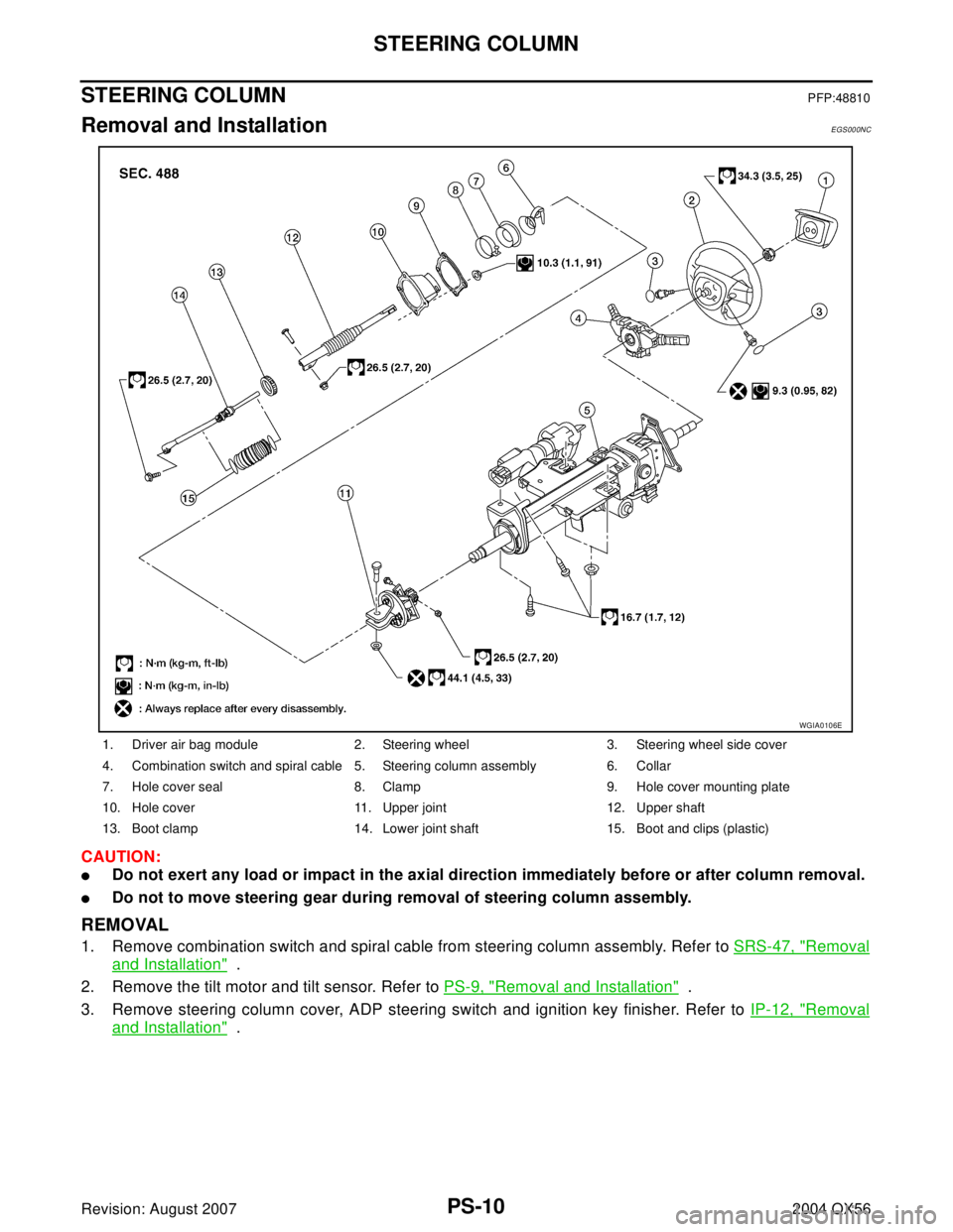
1. Driver air bag module 2. Steering wheel 3. Steering wheel side cover
4. Combination switch and spiral cable 5. Steering column assembly 6. Collar
7. Hole cover seal 8. Clamp 9. Hole cover mounting plate
10. Hole cover 11. Upper joint 12. Upper shaft
13. Boot clamp 14. Lower joint shaft 15. Boot and clips (plastic)
WGIA0106E
Page 2767 of 3371

PS-16
POWER STEERING GEAR AND LINKAGE
Revision: August 20072004 QX56
7. Remove steering outer socket from steering knuckle using Tool.
Be careful not to damage ball joint boot.
CAUTION:
Temporarily tighten mounting nut to prevent damage to
threads and to prevent Tool from coming off.
8. On 2WD models, remove stabilizer bar mounting bolts and reposition stabilizer bar. Refer to FSU-12,
"STABILIZER BAR" .
9. Remove oil piping (high pressure side and low pressure side)
from steering gear assembly, then drain fluid from piping.
10. Remove lower joint mounting bolt of lower shaft.
11. Remove mounting bolts and nuts of steering gear assembly
using power tool, and then remove steering gear assembly from
vehicle.
INSTALLATION
Installation is in the reverse order of removal.
�After removing/installing or replacing steering components, check wheel alignment. Refer to FSU-6,
"Front Wheel Alignment" .
�After adjusting wheel alignment, adjust neutral position of steering angle sensor. Refer to BRC-62,
"Adjustment of Steering Angle Sensor Neutral Position" . Tool number : HT72520000 (J-25730-A)
SDIA1434E
LGIA0032E
LGIA0029E
LGIA0024E
Page 2768 of 3371
POWER STEERING GEAR AND LINKAGE
PS-17
C
D
E
F
H
I
J
K
L
MA
B
PS
Revision: August 20072004 QX56
�With steering wheel in straight ahead position, make sure slit of
lower joint fits with the projection on rear cover cap, while check-
ing that mark on steering gear assembly aligns with mark on
rear cover cap
�After installation, bleed the air from the steering hydraulic system. Refer to PS-6, "Air Bleeding Hydraulic
System" .
INSPECTION AFTER INSTALLATION
Check if steering wheel turns smoothly when it is turned several times fully to the left and right lock positions.
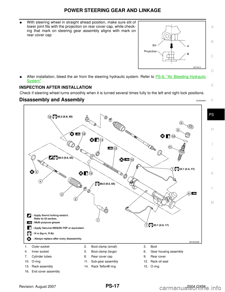
Disassembly and AssemblyEGS000MV
SST 4 91 C
1. Outer socket 2. Boot clamp (small) 3. Boot
4. Inner socket 5. Boot clamp (large) 6. Gear housing assembly
7. Cylinder tubes 8. Rear cover cap 9. Rear cover
10. O-ring 11. Sub-gear assembly 12. Rack oil seal
13. Rack assembly 14. Rack Teflon® ring 15. O-ring
16. End cover assembly
WGIA0093E
Page 2769 of 3371

PS-18
POWER STEERING GEAR AND LINKAGE
Revision: August 20072004 QX56
CAUTION:
�Secure steering gear assembly with a vise, using copper plates or something similar to prevent it
from being damaged. Do not grip cylinder with a vise.
�Before performing disassembly, clean steering gear assembly with kerosene. Be careful not to
bring any kerosene into contact with the discharge and return port connectors.
DISASSEMBLY
1. Remove cylinder tubes from gear housing assembly.
2. Remove rear cover cap from gear housing assembly.
3. Measure adjusting screw height from gear housing assembly,
then loosen adjusting screw.
CAUTION:
�Do not turn adjusting screw more than twice.
�Replace steering gear assembly when adjusting screw is
removed or more than twice.
4. Use a Tool to remove rear cover from sub-gear assembly.
5. Remove O-ring with a flat-bladed screwdriver, and pull out rear
cover.
6. Remove sub-gear assembly from gear housing assembly.
CAUTION:
In order to protect oil seal from any damage, pull sub-gear assembly straight out.
7. Loosen lock nut of outer socket, and remove outer socket.
8. Remove boot clamps of the small diameter side and the large diameter side, then remove boot.
CAUTION:
When removing boots, be careful not to damage inner socket and gear housing assembly. If they
are damaged, replace them to avoid fluid leaks.
SGIA0568E
Tool number : — (J-46213)
WGIA0146E
SGIA0508E
Page 2771 of 3371

PS-20
POWER STEERING GEAR AND LINKAGE
Revision: August 20072004 QX56
INSPECTION AFTER DISASSEMBLY
Boot
Check boot for cracks and deformation. Replace if necessary.
Rack Assembly
Check rack gear for damage and wear. Replace if necessary.
Sub-Gear Assembly
�Check pinion gear for damage and wear. Replace if necessary.
�Check bearing while rotating it. Replace bearing if bearing ball race was dented, worn, or damaged.
Gear Housing Assembly
Check gear housing assembly for damage and scratches (inner wall). Replace if necessary.
Outer Socket and Inner Socket Swing Torque
Hook a spring balance at the point shown in the figure. Confirm if the
reading is within the specification. When ball stud and inner socket
start moving the measured value must be within the specification. If
the reading is outside the specification, replace socket.
Outer Socket and Inner Socket Rotating Torque
Using Tool, check if reading is within the value specified below. If the
value is outside the standard, replace outer sockets.
Outer Socket and Inner Socket Axial End Play
Apply load of 490 N (50 kg, 110 lb) to ball stud axially. Use a dial
gauge to measure the amount of the movement that the stud makes.
Check if the reading is within specification. If the value is outside
specification, replace outer and inner sockets.
SGIA0547E
Item Outer socket Inner socket
Measuring point Cotter pin hole of stud Shown as "L": 83.2 mm (3.276 in)
Swing torque 0.3 − 2.9 N·m (0.03 − 0.29 kg-m, 3 − 25 in-lb) 1.0 − 7.8 N·m (0.11 − 0.79 kg-m, 9 − 69 in-lb)
Measuring value 4.84 − 46.7 N (0.50 − 4.7 kg, 4 - 34 lb) 12.1 − 93.7 N (1.3 − 9.5 kg, 9 − 69 lb)
Tool number : ST3127S000 (J-25765-A)
Rotating torque : 0.3 − 2.9 N·m (0.03 − 0.29 kg-m,
3 − 25 in-lb)
SST 8 82 B
Outer socket : 0.5 mm (0.020 in) or less
Inner socket : 0.2 mm (0.008 in) or less
SGIA0057E
Page 2775 of 3371

PS-24
POWER STEERING GEAR AND LINKAGE
Revision: August 20072004 QX56
15. Measure pinion rotating torque using Tool, then confirm whether
the reading is within the specified value. If the reading is not
within the specified value, readjust screw angle with adjusting
screw. If the reading is still not within the specified value or the
rotating torque of adjusting screw is less than 5 N·m (0.51 kg-m,
44 in-lb), replace the steering gear assembly.
16. Turn pinion to the full left lock position with inner socket to gear housing assembly.
17. Mount dial gauge to rack as shown. Measure vertical movement
of rack when pinion is turned counterclockwise with torque of
19.6 N·m (2.0 kg-m, 14 ft-lb). Check if reading is within the spec-
ified value. If reading is outside of the specification, readjust
screw angle with adjusting screw. If reading is still outside of
specification, or if the rotating torque of adjusting screw is less
than 5 N·m (0.51 kg-m, 44 in-lb), replace the steering gear
assembly.
18. Install large-diameter side of boot to gear housing assembly.
19. Install small-diameter side of boot to the mounting groove of
inner socket boot.
20. Install boot clamp to the small-diameter side of boot.Pinion rotating torque:
Around neutral position (within ±100°)
Average “A”:
0.8 − 2.0 N·m (0.09 − 0.20 kg-m, 7 − 17 in-lb)
Other than above (more than ±100°)
Maximum variation “B”:
2.3 N·m (0.23 kg-m, 20 in-lb)
SGIA0160E
Tool number : ST3127S000 (J25765-A)
WGIA0148E
Amount of vertical movement with rack Less than 0.265 mm (0.010 in)
Measuring pointAxial direction of rack5 mm (0.197 in) away from end of
gear housing
Radius direction of rack Shaft direction of adjusting screw
SGIA0550E
Page 2776 of 3371
POWER STEERING GEAR AND LINKAGE
PS-25
C
D
E
F
H
I
J
K
L
MA
B
PS
Revision: August 20072004 QX56
21. Install new boot clamps and crimp securely using Tool.
CAUTION:
Do not reuse boot clamps.
22. Install cylinder tubes to gear housing assembly.
23. Install lock nut and outer socket to inner socket.
24. Tighten lightly tie-rod in specified length “L”, then tighten lock nut
at specified torque. Refer to PS-17, "
Disassembly and Assem-
bly" . Reconfirm if tie-rod length is within limit of specified length
“L”.
CAUTION:
Perform toe-in adjustment after this procedure. Length
achieved after toe-in adjustment is not necessarily the
value given here.Tool number : KV40107300 ( — )
AST 1 39
Inner socket length “L” : 115.2 mm (4.54 in)
SGIA0167E
Page 2795 of 3371

RAX-8
REAR DRIVE SHAFT
Revision: August 20072004 QX56
5. Separate the drive shaft from the wheel hub and bearing assembly by lightly tapping the end with a suit-
able hammer and wood block. If it is difficult to separate, use a suitable puller.
6. Remove the drive shaft.
CAUTION:
When removing the drive shaft, do not bend at an excessive angle to the drive shaft joint. Do not
excessively extend the slide joint.
INSPECTION AFTER REMOVAL
�Move the joint up and down, left and right, and in the axial direc-
tion. Check for any rough movement or significant looseness.
�Check the boot for cracks or other damage, and for any grease
leakage.
�If necessary, disassemble the drive shaft, and repair as neces-
sary.
INSTALLATION
Installation is in the reverse order of removal.
�Apply grease 44003 7S000CM to contact surface (A) between
wheel hub and bearing assembly and drive shaft as shown. Use
sufficient grease to completely coat contact area.
�Do not reuse the drive shaft inside flange bolts, discard after
removal and use new drive shaft bolts for installation.
�Do not reuse cotter pin, discard after removal and use a new
cotter pin for installation.
Disassembly and AssemblyEDS001AW
RAA0030D
WDIA0299E
1. Plug 2. Housing 3. Snap ring
4. Ball cage, steel ball, liner race assembly 5. Stopper ring 6. Boot band
7. Boot 8. Shaft 9. Circlip
10. Joint sub-assembly
WDIA0221E