Page 1307 of 3371
EC-116Revision: August 2007
TROUBLE DIAGNOSIS
2004 QX56
Generic Scan Tool (GST) FunctionUBS00H06
DESCRIPTION
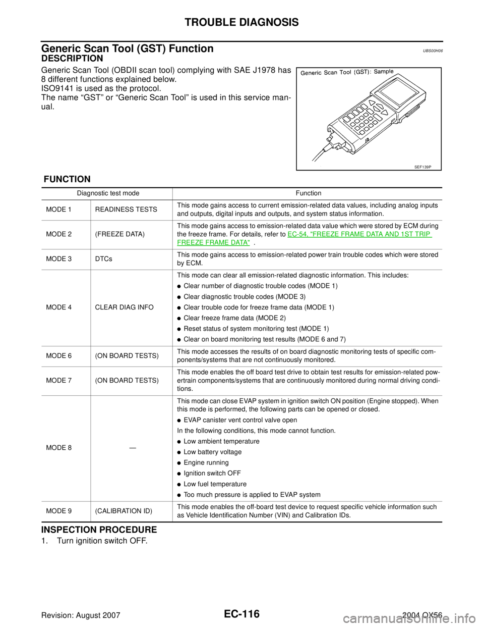
Generic Scan Tool (OBDII scan tool) complying with SAE J1978 has
8 different functions explained below.
ISO9141 is used as the protocol.
The name “GST” or “Generic Scan Tool” is used in this service man-
ual.
FUNCTION
INSPECTION PROCEDURE
1. Turn ignition switch OFF.
SEF 1 39 P
Diagnostic test mode Function
MODE 1 READINESS TESTSThis mode gains access to current emission-related data values, including analog inputs
and outputs, digital inputs and outputs, and system status information.
MODE 2 (FREEZE DATA)This mode gains access to emission-related data value which were stored by ECM during
the freeze frame. For details, refer to EC-54, "
FREEZE FRAME DATA AND 1ST TRIP
FREEZE FRAME DATA" .
MODE 3 DTCsThis mode gains access to emission-related power train trouble codes which were stored
by ECM.
MODE 4 CLEAR DIAG INFOThis mode can clear all emission-related diagnostic information. This includes:
�Clear number of diagnostic trouble codes (MODE 1)
�Clear diagnostic trouble codes (MODE 3)
�Clear trouble code for freeze frame data (MODE 1)
�Clear freeze frame data (MODE 2)
�Reset status of system monitoring test (MODE 1)
�Clear on board monitoring test results (MODE 6 and 7)
MODE 6 (ON BOARD TESTS)This mode accesses the results of on board diagnostic monitoring tests of specific com-
ponents/systems that are not continuously monitored.
MODE 7 (ON BOARD TESTS)This mode enables the off board test drive to obtain test results for emission-related pow-
ertrain components/systems that are continuously monitored during normal driving condi-
tions.
MODE 8 —This mode can close EVAP system in ignition switch ON position (Engine stopped). When
this mode is performed, the following parts can be opened or closed.
�EVAP canister vent control valve open
In the following conditions, this mode cannot function.
�Low ambient temperature
�Low battery voltage
�Engine running
�Ignition switch OFF
�Low fuel temperature
�Too much pressure is applied to EVAP system
MODE 9 (CALIBRATION ID)This mode enables the off-board test device to request specific vehicle information such
as Vehicle Identification Number (VIN) and Calibration IDs.
Page 1308 of 3371
TROUBLE DIAGNOSIS
EC-117
C
D
E
F
G
H
I
J
K
L
MA
EC
Revision: August 20072004 QX56
2. Connect GST to data link connector, which is located under LH
dash panel near the center console.
3. Turn ignition switch ON.
4. Enter the program according to instruction on the screen or in
the operation manual.
(*: Regarding GST screens in this section, sample screens are
shown.)
5. Perform each diagnostic mode according to each service proce-
dure.
For further information, see the GST Operation Manual of
the tool maker.
BBIA0369E
SEF 3 98 S
SEF 4 16 S
Page 1464 of 3371
DTC P0441 EVAP CONTROL SYSTEM
EC-273
C
D
E
F
G
H
I
J
K
L
MA
EC
Revision: August 20072004 QX56
9. If NG, go to EC-273, "Diagnostic Procedure" .
Diagnostic ProcedureUBS00H4N
1. CHECK EVAP CANISTER
1. Turn ignition switch OFF.
2. Check EVAP canister for cracks.
OK or NG
OK (With CONSULT-II)>>GO TO 2.
OK (Without CONSULT-II)>>GO TO 3.
NG >> Replace EVAP canister.
2. CHECK PURGE FLOW
With CONSULT-II
1. Disconnect vacuum hose connected to EVAP canister purge volume control solenoid valve at EVAP ser-
vice port and install vacuum gauge. For the location of EVAP service port, refer to EC-634, "
EVAPORA-
TIVE EMISSION LINE DRAWING" .
2. Start engine and let it idle.
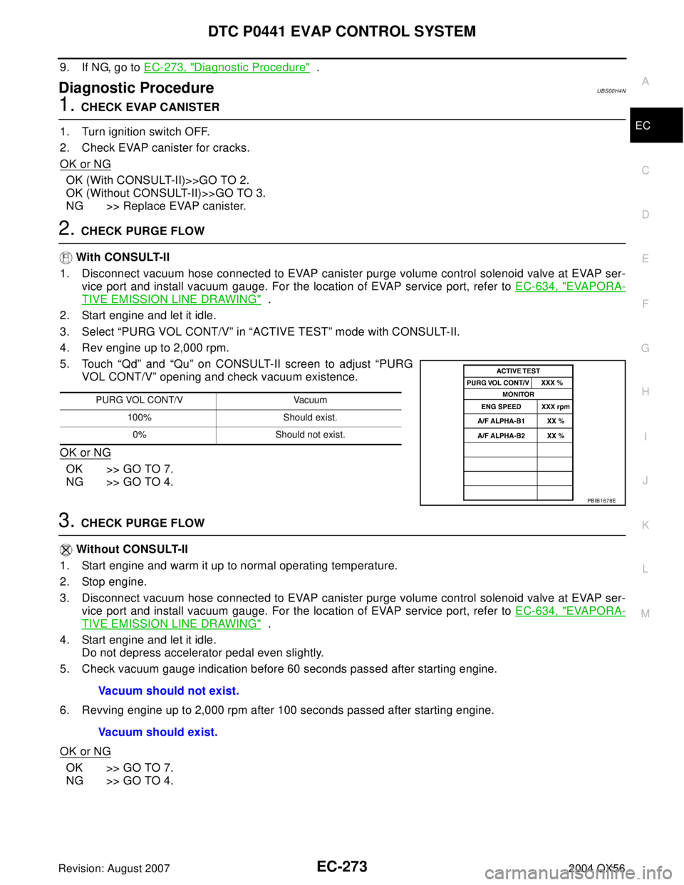
3. Select “PURG VOL CONT/V” in “ACTIVE TEST” mode with CONSULT-II.
4. Rev engine up to 2,000 rpm.
5. Touch “Qd” and “Qu” on CONSULT-II screen to adjust “PURG
VOL CONT/V” opening and check vacuum existence.
OK or NG
OK >> GO TO 7.
NG >> GO TO 4.
3. CHECK PURGE FLOW
Without CONSULT-II
1. Start engine and warm it up to normal operating temperature.
2. Stop engine.
3. Disconnect vacuum hose connected to EVAP canister purge volume control solenoid valve at EVAP ser-
vice port and install vacuum gauge. For the location of EVAP service port, refer to EC-634, "
EVAPORA-
TIVE EMISSION LINE DRAWING" .
4. Start engine and let it idle.
Do not depress accelerator pedal even slightly.
5. Check vacuum gauge indication before 60 seconds passed after starting engine.
6. Revving engine up to 2,000 rpm after 100 seconds passed after starting engine.
OK or NG
OK >> GO TO 7.
NG >> GO TO 4.
PURG VOL CONT/V Vacuum
100% Should exist.
0% Should not exist.
PBIB1678E
Vacuum should not exist.
Vacuum should exist.
Page 1465 of 3371
EC-274Revision: August 2007
DTC P0441 EVAP CONTROL SYSTEM
2004 QX56
4. CHECK EVAP PURGE LINE
1. Turn ignition switch OFF.
2. Check EVAP purge line for improper connection or disconnection.
Refer to EC-634, "
EVAPORATIVE EMISSION LINE DRAWING" .
OK or NG
OK >> GO TO 5.
NG >> Repair it.
5. CHECK EVAP PURGE HOSE AND PURGE PORT
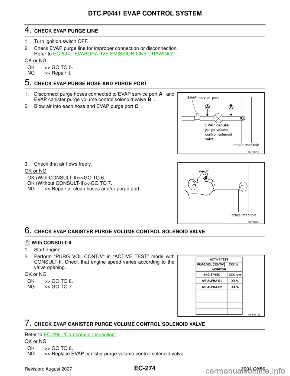
1. Disconnect purge hoses connected to EVAP service port A and
EVAP canister purge volume control solenoid valve B .
2. Blow air into each hose and EVAP purge port C .
3. Check that air flows freely.
OK or NG
OK (With CONSULT-II)>>GO TO 6.
OK (Without CONSULT-II)>>GO TO 7.
NG >> Repair or clean hoses and/or purge port.
6. CHECK EVAP CANISTER PURGE VOLUME CONTROL SOLENOID VALVE
With CONSULT-II
1. Start engine.
2. Perform “PURG VOL CONT/V” in “ACTIVE TEST” mode with
CONSULT-II. Check that engine speed varies according to the
valve opening.
OK or NG
OK >> GO TO 8.
NG >> GO TO 7.
7. CHECK EVAP CANISTER PURGE VOLUME CONTROL SOLENOID VALVE
Refer to EC-290, "
Component Inspection" .
OK or NG
OK >> GO TO 8.
NG >> Replace EVAP canister purge volume control solenoid valve.
SEF 3 67 U
SEF 3 68 U
PBIB1678E
Page 1470 of 3371
DTC P0442 EVAP CONTROL SYSTEM
EC-279
C
D
E
F
G
H
I
J
K
L
MA
EC
Revision: August 20072004 QX56
5. INSTALL THE PRESSURE PUMP
To locate the EVAP leak, install EVAP service port adapter and pres-
sure pump to EVAP service port securely. For the location of EVAP
service port, refer to EC-634, "
EVAPORATIVE EMISSION LINE
DRAWING" .
NOTE:
Improper installation of the EVAP service port adapter to the EVAP service port may cause leaking.
With CONSULT-II>>GO TO 6.
Without CONSULT-II>>GO TO 7.
BBIA0366E
SEF 9 16 U
Page 1472 of 3371
DTC P0442 EVAP CONTROL SYSTEM
EC-281
C
D
E
F
G
H
I
J
K
L
MA
EC
Revision: August 20072004 QX56
7. CHECK FOR EVAP LEAK
Without CONSULT-II
1. Turn ignition switch OFF.
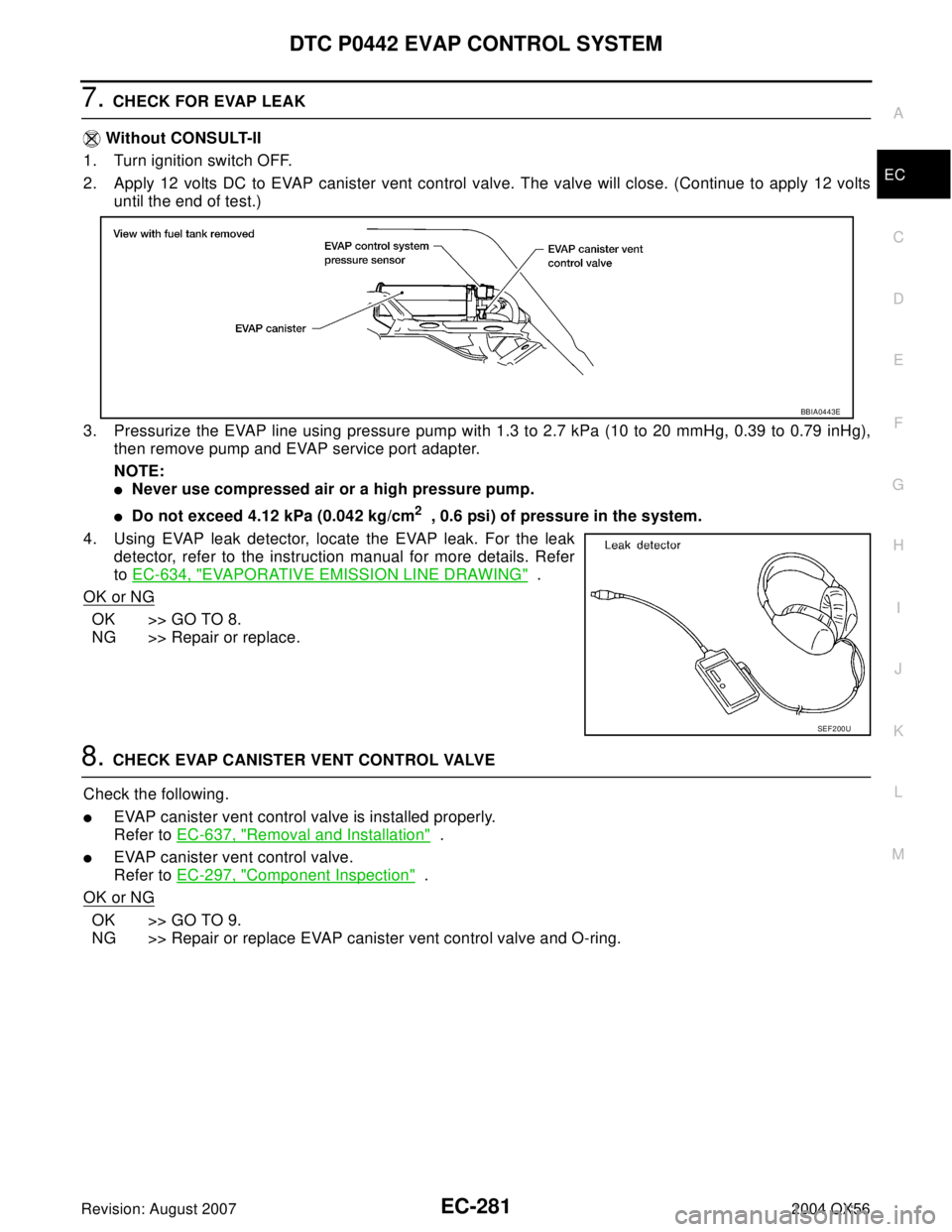
2. Apply 12 volts DC to EVAP canister vent control valve. The valve will close. (Continue to apply 12 volts
until the end of test.)
3. Pressurize the EVAP line using pressure pump with 1.3 to 2.7 kPa (10 to 20 mmHg, 0.39 to 0.79 inHg),
then remove pump and EVAP service port adapter.
NOTE:
�Never use compressed air or a high pressure pump.
�Do not exceed 4.12 kPa (0.042 kg/cm2 , 0.6 psi) of pressure in the system.
4. Using EVAP leak detector, locate the EVAP leak. For the leak
detector, refer to the instruction manual for more details. Refer
to EC-634, "
EVAPORATIVE EMISSION LINE DRAWING" .
OK or NG
OK >> GO TO 8.
NG >> Repair or replace.
8. CHECK EVAP CANISTER VENT CONTROL VALVE
Check the following.
�EVAP canister vent control valve is installed properly.
Refer to EC-637, "
Removal and Installation" .
�EVAP canister vent control valve.
Refer to EC-297, "
Component Inspection" .
OK or NG
OK >> GO TO 9.
NG >> Repair or replace EVAP canister vent control valve and O-ring.
BBIA0443E
SEF 2 00 U
Page 1473 of 3371
EC-282Revision: August 2007
DTC P0442 EVAP CONTROL SYSTEM
2004 QX56
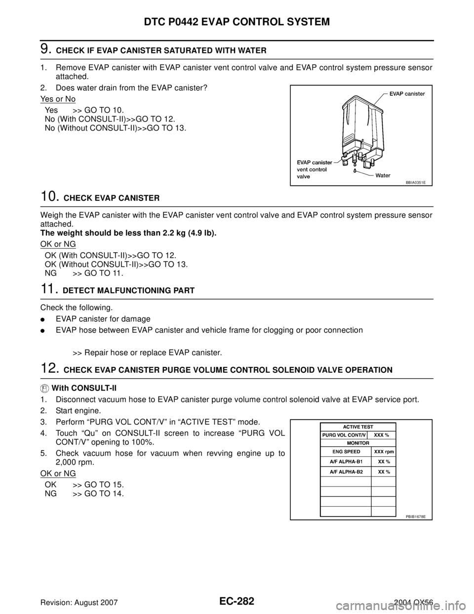
9. CHECK IF EVAP CANISTER SATURATED WITH WATER
1. Remove EVAP canister with EVAP canister vent control valve and EVAP control system pressure sensor
attached.
2. Does water drain from the EVAP canister?
Ye s o r N o
Yes >> GO TO 10.
No (With CONSULT-II)>>GO TO 12.
No (Without CONSULT-II)>>GO TO 13.
10. CHECK EVAP CANISTER
Weigh the EVAP canister with the EVAP canister vent control valve and EVAP control system pressure sensor
attached.
The weight should be less than 2.2 kg (4.9 lb).
OK or NG
OK (With CONSULT-II)>>GO TO 12.
OK (Without CONSULT-II)>>GO TO 13.
NG >> GO TO 11.
11 . DETECT MALFUNCTIONING PART
Check the following.
�EVAP canister for damage
�EVAP hose between EVAP canister and vehicle frame for clogging or poor connection
>> Repair hose or replace EVAP canister.
12. CHECK EVAP CANISTER PURGE VOLUME CONTROL SOLENOID VALVE OPERATION
With CONSULT-II
1. Disconnect vacuum hose to EVAP canister purge volume control solenoid valve at EVAP service port.
2. Start engine.
3. Perform “PURG VOL CONT/V” in “ACTIVE TEST” mode.
4. Touch “Qu” on CONSULT-II screen to increase “PURG VOL
CONT/V” opening to 100%.
5. Check vacuum hose for vacuum when revving engine up to
2,000 rpm.
OK or NG
OK >> GO TO 15.
NG >> GO TO 14.
BBIA0351E
PBIB1678E
Page 1474 of 3371
DTC P0442 EVAP CONTROL SYSTEM
EC-283
C
D
E
F
G
H
I
J
K
L
MA
EC
Revision: August 20072004 QX56
13. CHECK EVAP CANISTER PURGE VOLUME CONTROL SOLENOID VALVE OPERATION
Without CONSULT-II
1. Start engine and warm it up to normal operating temperature.
2. Stop engine.
3. Disconnect vacuum hose to EVAP canister purge volume control solenoid valve at EVAP service port.
4. Start engine and let it idle for at least 80 seconds.
5. Check vacuum hose for vacuum when revving engine up to 2,000 rpm.
OK or NG
OK >> GO TO 16.
NG >> GO TO 14.
14. CHECK VACUUM HOSE
Check vacuum hoses for clogging or disconnection. Refer to EC-24, "
Vacuum Hose Drawing" .
OK or NG
OK >> GO TO 15.
NG >> Repair or reconnect the hose.
15. CHECK EVAP CANISTER PURGE VOLUME CONTROL SOLENOID VALVE
Refer to EC-290, "
Component Inspection" .
OK or NG
OK >> GO TO 16.
NG >> Replace EVAP canister purge volume control solenoid valve.
16. CHECK FUEL TANK TEMPERATURE SENSOR
Refer to EC-229, "
Component Inspection" .
OK or NG
OK >> GO TO 17.
NG >> Replace fuel level sensor unit.
17. CHECK EVAP CONTROL SYSTEM PRESSURE SENSOR
Refer to EC-301, "
Component Inspection" .
OK or NG
OK >> GO TO 18.
NG >> Replace EVAP control system pressure sensor.
18. CHECK EVAP PURGE LINE
Check EVAP purge line (pipe, rubber tube, fuel tank and EVAP canister) for cracks or improper connection.
Refer to EC-634, "
EVAPORATIVE EMISSION LINE DRAWING" .
OK or NG
OK >> GO TO 19.
NG >> Repair or reconnect the hose.
19. CLEAN EVAP PURGE LINE
Clean EVAP purge line (pipe and rubber tube) using air blower.
>> GO TO 20. Vacuum should exist.