Page 3096 of 3371
![INFINITI QX56 2004 Factory Service Manual TROUBLE DIAGNOSIS
SRS-35
C
D
E
F
G
I
J
K
L
MA
B
SRS
Revision: August 20072004 QX56
FR CURTN MODULE RH
[OPEN]
[B1193]�The RH side front curtain air bag module circuit is open. 1. Visually check the wir](/manual-img/42/57034/w960_57034-3095.png "INFINITI QX56 2004 Factory Service Manual TROUBLE DIAGNOSIS
SRS-35
C
D
E
F
G
I
J
K
L
MA
B
SRS
Revision: August 20072004 QX56
FR CURTN MODULE RH
[OPEN]
[B1193]�The RH side front curtain air bag module circuit is open. 1. Visually check the wir")
TROUBLE DIAGNOSIS
SRS-35
C
D
E
F
G
I
J
K
L
MA
B
SRS
Revision: August 20072004 QX56
FR CURTN MODULE RH
[OPEN]
[B1193]�The RH side front curtain air bag module circuit is open. 1. Visually check the wiring harness
connection.
2. Replace the harness if it has visible
damage.
3. Replace RH side curtain air bag
module.
4. Replace the air bag diagnosis sen-
sor unit.
5. Replace the related harness. FR CURTN MODULE RH
[VB-SHORT]
[B1194]
�The RH side front curtain air bag module circuit is shorted
to some power supply circuits.
FR CURTN MODULE RH
[GND-SHORT]
[B1195]
�The RH side front curtain air bag module circuit is shorted
to ground.
FR CURTN MODULE RH
[SHORT]
[B1196]
�The circuits for the RH side front curtain air bag module are
shorted to each other.
CURTAIN MODULE LH
[OPEN]
[B1150]
�The LH side rear curtain air bag module circuit is open. 1. Visually check the wiring harness
connection.
2. Replace the harness if it has visible
damage.
3. Replace LH side curtain air bag
module.
4. Replace the air bag diagnosis sen-
sor unit.
5. Replace the related harness. CURTAIN MODULE LH
[VB-SHORT]
[B1151]
�The LH side rear curtain air bag module circuit is shorted to
some power supply circuits.
CURTAIN MODULE LH
[GND-SHORT]
[B1152]
�The LH side rear curtain air bag module circuit is shorted to
ground.
CURTAIN MODULE LH
[SHORT]
[B1153]
�The circuits for the LH side rear curtain air bag module are
shorted to each other.
CURTAIN MODULE RH
[OPEN]
[B1145]
�The RH side rear curtain air bag module circuit is open. 1. Visually check the wiring harness
connection.
2. Replace the harness if it has visible
damage.
3. Replace RH side curtain air bag
module.
4. Replace the air bag diagnosis sen-
sor unit.
5. Replace the related harness. CURTAIN MODULE RH
[VB-SHORT]
[B1146]
�The RH side rear curtain air bag module circuit is shorted
to some power supply circuits.
CURTAIN MODULE RH
[GND-SHORT]
[B1147]
�The RH side rear curtain air bag module circuit is shorted
to ground.
CURTAIN MODULE RH
[SHORT]
[B1148]
�The circuits for the RH side rear curtain air bag module are
shorted to each other.
CONTROL UNIT
[B1XXX]
�Air bag diagnosis sensor unit is malfunctioning. 1. Visually check the wiring harness
connection.
2. Replace the diagnosis sensor unit.
OCCUPANT SENS C/U
[UNIT FAIL]
[B1017], [B1020] or [B1021]
�Occupant classification system is malfunctioning. 1. Replace RH front seat cushion/
occupant classification system con-
trol unit assembly.
OCCUPANT SENS C/U
[COMM FAIL]
[B1022]
�Communication between the occupant classification sys-
tem control unit and air bag diagnosis sensor unit is inter-
rupted.1. Visually check the wiring harness
connection.
2. Replace the harness if it has visible
damage.
3. Replace RH front seat cushion/
occupant classification system con-
trol unit assembly.
4. Replace the air bag diagnosis sen-
sor unit.
5. Replace the related harness.
OCCUPANT SENS
[UNIT FAIL]
[B1018]
�Occupant classification sensor is malfunctioning. 1. Replace RH front seat cushion/
occupant classification system con-
trol unit assembly. Diagnostic item ExplanationRepair order
Recheck SRS at each replacement
Page 3097 of 3371
SRS-36
TROUBLE DIAGNOSIS
Revision: August 20072004 QX56
BELT TENSION SENS
[UNIT FAIL]
[B1019]
�Belt tension sensor is malfunctioning. 1. Visually check the wiring harness
connection.
2. Replace the harness if it has visible
damage.
3. Replace RH front seat belt assem-
bly.
4. Replace RH front seat cushion/
occupant classification system con-
trol unit assembly.
PASS A/B INDCTR CKT
[B1023]
�Front passenger air bag off indicator is malfunctioning. 1. Visually check the wiring harness
connection.
2. Replace the harness if it has visible
damage.
3. Replace front passenger air bag off
indicator.
4. Replace the air bag diagnosis sen-
sor unit.
5. Replace the related harness. Diagnostic item ExplanationRepair order
Recheck SRS at each replacement
Page 3098 of 3371
TROUBLE DIAGNOSIS
SRS-37
C
D
E
F
G
I
J
K
L
MA
B
SRS
Revision: August 20072004 QX56
Trouble Diagnosis Without CONSULT-IIEHS000WI
DIAGNOSTIC PROCEDURE 6
Inspect SRS Malfunction Using "AIR BAG" Warning Lamp—Diagnosis Mode
NOTE:
SRS will not enter Diagnosis mode if no malfunction is detected in User mode.
1. Turn ignition switch ON.
2. After “AIR BAG” warning lamp lights for 7 seconds, turn ignition switch OFF within 1 second.
3. Wait more than 3 seconds.
4. Repeat steps 1 to 3 two more times (3 times total).
5. Turn ignition switch ON.
SRS is now in Diagnosis mode.
"AIR BAG" warning lamp operates in Diagnosis mode as follows:
Page 3104 of 3371

TROUBLE DIAGNOSIS
SRS-43
C
D
E
F
G
I
J
K
L
MA
B
SRS
Revision: August 20072004 QX56
Trouble Diagnosis: “AIR BAG” Warning Lamp Does Not Turn OffEHS000WJ
DIAGNOSTIC PROCEDURE 6
1. CHECK CONDITION OF AIR BAG MODULE
Inspect for deployed air bag modules or seat belt pre-tensioners.
Are air bag modules or seat belt pre-tensioners deployed?
Yes >> Refer to SRS-60, "COLLISION DIAGNOSIS" .
No >> GO TO 2.
2. CHECK THE AIR BAG FUSE
Check 10A fuse [No. 13, located in the fuse block (J/B)].
Refer to PG-4, "
POWER SUPPLY ROUTING CIRCUIT" .
OK or NG
OK >> GO TO 4.
NG >> GO TO 3.
3. CHECK AIR BAG FUSE AGAIN
Replace 10A fuse [No. 13, located in the fuse block (J/B)] and turn ignition switch ON.
Does the fuse blow again?
Yes >> Repair harness.
No >> Inspection End.
4. CHECK AIR BAG DIAGNOSIS SENSOR UNIT
Connect CONSULT-II and touch “START”.
Is
“AIR BAG” displayed on CONSULT-II?
Yes >> GO TO 5.
No >> Visually inspect the air bag diagnosis sensor unit har-
ness connections. If the connections are OK, replace
the air bag diagnosis sensor unit. Refer to SRS-58,
"Removal and Installation" .
5. CHECK HARNESS CONNECTION
Check for loose connections between the combination meter and the air bag diagnosis sensor unit.
OK or NG
OK >> Replace air bag diagnosis sensor unit. Refer to SRS-58, "Removal and Installation" .
NG >> Properly connect the combination meter and air bag diagnosis sensor unit harness connectors. If
“AIR BAG” warning lamp still does not turn off, replace the wiring harness.
BCIA0030E
Page 3105 of 3371
SRS-44
TROUBLE DIAGNOSIS
Revision: August 20072004 QX56
Trouble Diagnosis: “AIR BAG” Warning Lamp Does Not Turn OnEHS000WK
DIAGNOSTIC PROCEDURE 7
1. CHECK METER FUSE
Check the 10A fuse [No. 14, located in the fuse block (J/B)].
Refer to PG-4, "
POWER SUPPLY ROUTING CIRCUIT" .
OK or NG
OK >> GO TO 3.
NG >> GO TO 2.
2. CHECK METER FUSE AGAIN
Replace 10A fuse [No. 14, located in the fuse block (J/B)] and turn ignition switch ON.
Does the fuse blow again?
Yes >> Repair harness.
No >> Inspection End.
3. CHECK HARNESS CONNECTION BETWEEN DIAGNOSIS SENSOR UNIT AND COMBINATION
METER
Disconnect the air bag diagnosis sensor unit harness connectors and turn ignition switch ON.
Does
“AIR BAG” warning lamp turn on?
Yes >> Replace the air bag diagnosis sensor unit. Refer to SRS-58, "Removal and Installation" .
No >> Check the combination meter ground circuits.
Page 3106 of 3371

DRIVER AIR BAG MODULE
SRS-45
C
D
E
F
G
I
J
K
L
MA
B
SRS
Revision: August 20072004 QX56
DRIVER AIR BAG MODULEPFP:K8510
Removal and InstallationEHS000WL
REMOVAL
CAUTION:
�Do not attempt to repair or replace damaged direct-connect SRS component connectors. If a
driver air bag direct-connect harness connector is damaged, the spiral cable must be replaced.
�Before servicing the SRS, turn ignition switch OFF, disconnect both battery cables and wait at
least 3 minutes.
�When servicing the SRS, do not work from directly in front of air bag module.
1. Remove the left and right side lids and bolts.
2. Lift the driver air bag module from the steering wheel.
3. Disconnect the horn connector and air bag harness, then remove the driver air bag module.
�For removal/installation of the direct-connect SRS connectors, refer to SRS-7, "Direct-connect SRS
Component Connectors" .
CAUTION:
�When servicing the SRS, do not work from directly in front of air bag module.
1. Horn harness 2. Steering wheel hook 3. Inflator harness
4. Side lids RH/LH 5. Driver air bag module 6. Steering wheel
WHIA0159E
WHIA0184E
Page 3107 of 3371
 into air
bag module or harn")
SRS-46
DRIVER AIR BAG MODULE
Revision: August 20072004 QX56
�Always place air bag module with pad side facing upward.
�Do not insert any foreign objects (screwdriver, etc.) into air
bag module or harness connectors.
�Do not disassemble air bag module.
�Do not use old bolts after removal; replace with new bolts.
�Do not expose the air bag module to temperatures exceed-
ing 90°C (194°F).
�Replace the air bag module if it has been dropped or sus-
tained an impact.
�Do not allow oil, grease or water to come in contact with the
air bag module.
INSTALLATION
To install, reverse the removal procedure.
�If driver air bag module is being replaced due to deployment, spiral cable must also be replaced. Refer to
SRS-47, "
SPIRAL CABLE" .
�For removal/installation of the direct-connect SRS connectors, refer to SRS-7, "Direct-connect SRS Com-
ponent Connectors" .
�After the work is completed, perform self-diagnosis to check that no malfunction is detected. Refer to
SRS-20, "
SRS Operation Check" .
LHIA0052E
SBF 8 14 E
Page 3108 of 3371
SPIRAL CABLE
SRS-47
C
D
E
F
G
I
J
K
L
MA
B
SRS
Revision: August 20072004 QX56
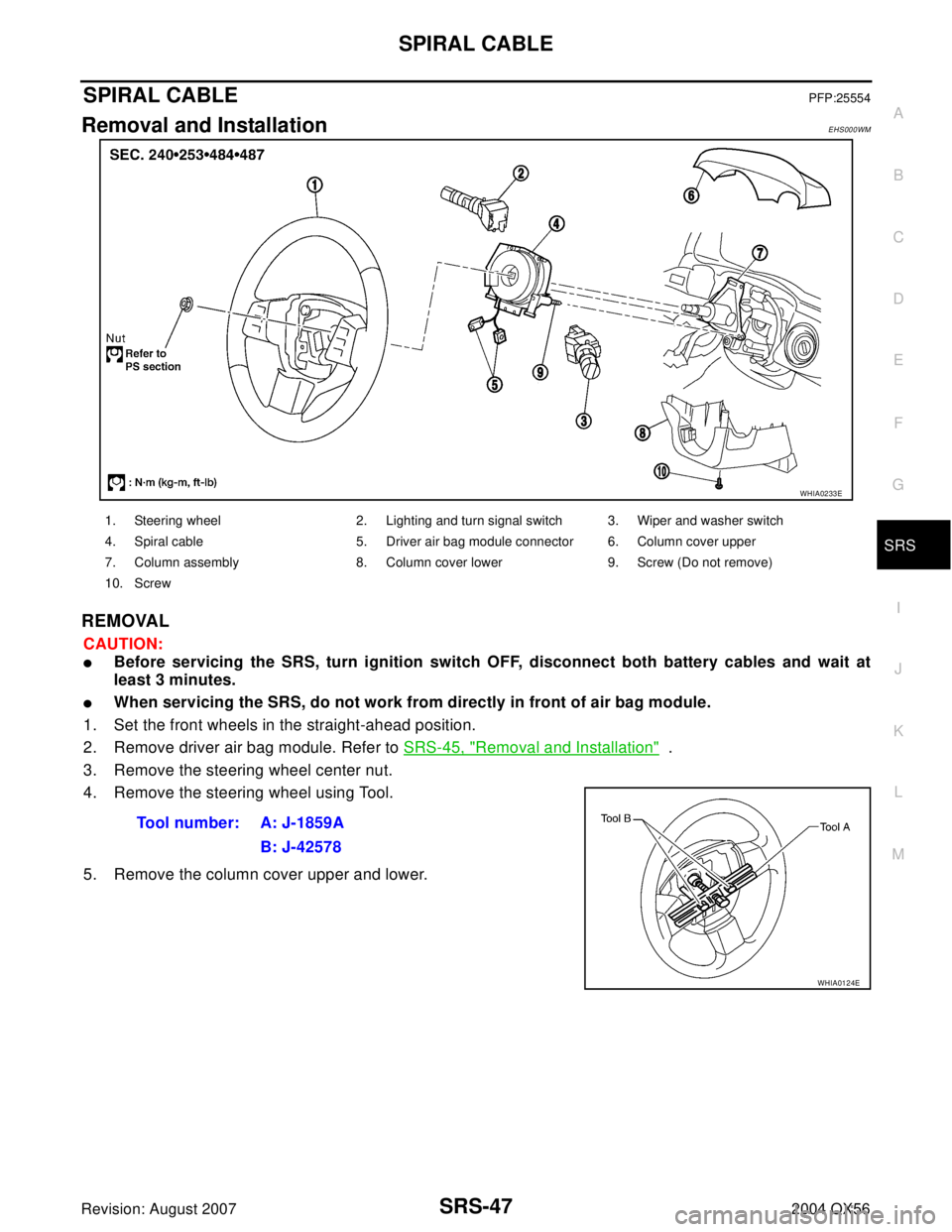
SPIRAL CABLEPFP:25554
Removal and InstallationEHS000WM
REMOVAL
CAUTION:
�Before servicing the SRS, turn ignition switch OFF, disconnect both battery cables and wait at
least 3 minutes.
�When servicing the SRS, do not work from directly in front of air bag module.
1. Set the front wheels in the straight-ahead position.
2. Remove driver air bag module. Refer to SRS-45, "
Removal and Installation" .
3. Remove the steering wheel center nut.
4. Remove the steering wheel using Tool.
5. Remove the column cover upper and lower.
WHIA0233E
1. Steering wheel 2. Lighting and turn signal switch 3. Wiper and washer switch
4. Spiral cable 5. Driver air bag module connector 6. Column cover upper
7. Column assembly 8. Column cover lower 9. Screw (Do not remove)
10. Screw
Tool number: A: J-1859A
B: J-42578
WHIA0124E