Page 2929 of 3371
SC-8
BATTERY
Revision: August 20072004 QX56
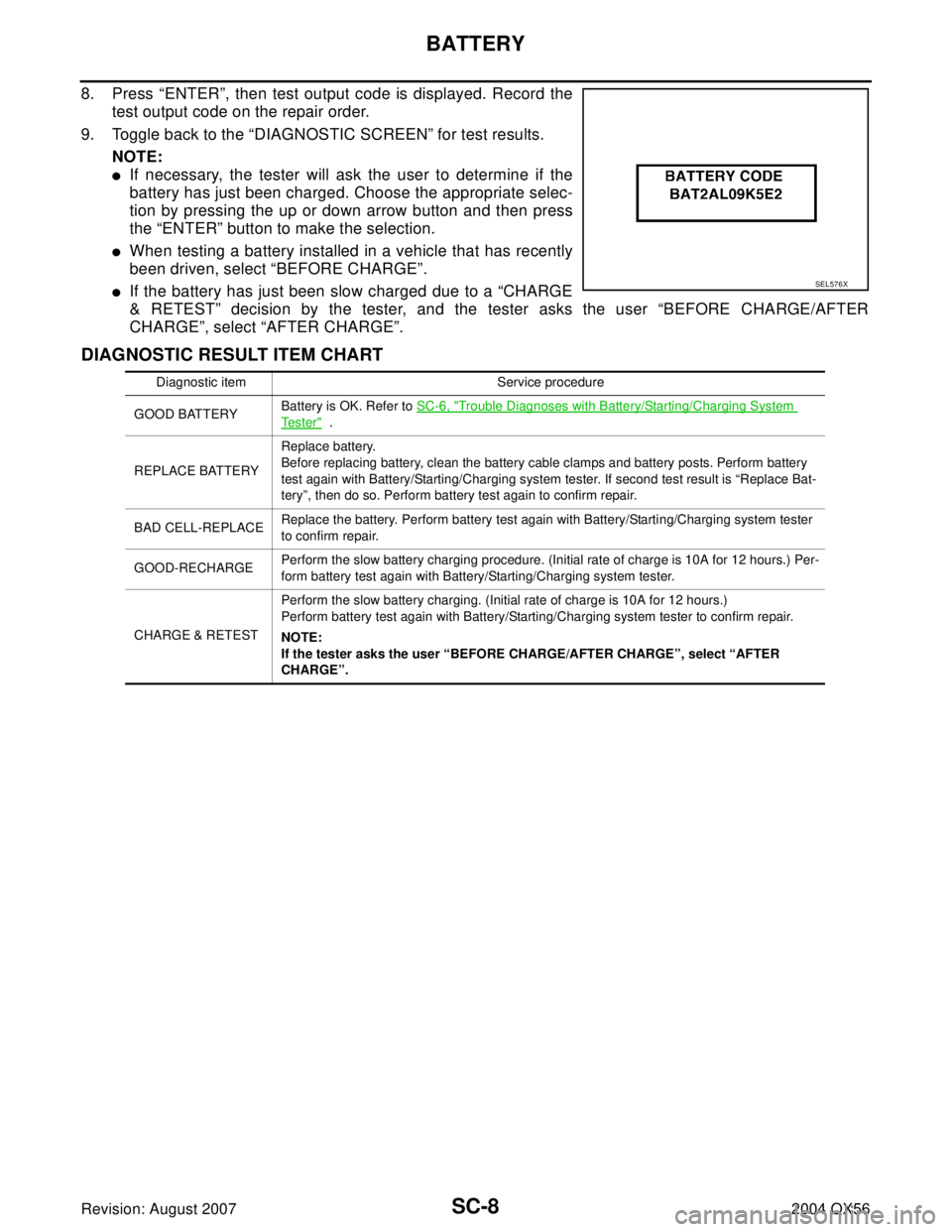
8. Press “ENTER”, then test output code is displayed. Record the
test output code on the repair order.
9. Toggle back to the “DIAGNOSTIC SCREEN” for test results.
NOTE:
�If necessary, the tester will ask the user to determine if the
battery has just been charged. Choose the appropriate selec-
tion by pressing the up or down arrow button and then press
the “ENTER” button to make the selection.
�When testing a battery installed in a vehicle that has recently
been driven, select “BEFORE CHARGE”.
�If the battery has just been slow charged due to a “CHARGE
& RETEST” decision by the tester, and the tester asks the user “BEFORE CHARGE/AFTER
CHARGE”, select “AFTER CHARGE”.
DIAGNOSTIC RESULT ITEM CHART
SEL576X
Diagnostic item Service procedure
GOOD BATTERYBattery is OK. Refer to SC-6, "
Trouble Diagnoses with Battery/Starting/Charging System
Te s t e r" .
REPLACE BATTERYReplace battery.
Before replacing battery, clean the battery cable clamps and battery posts. Perform battery
test again with Battery/Starting/Charging system tester. If second test result is “Replace Bat-
tery”, then do so. Perform battery test again to confirm repair.
BAD CELL-REPLACEReplace the battery. Perform battery test again with Battery/Starting/Charging system tester
to confirm repair.
GOOD-RECHARGEPerform the slow battery charging procedure. (Initial rate of charge is 10A for 12 hours.) Per-
form battery test again with Battery/Starting/Charging system tester.
CHARGE & RETESTPerform the slow battery charging. (Initial rate of charge is 10A for 12 hours.)
Perform battery test again with Battery/Starting/Charging system tester to confirm repair.
NOTE:
If the tester asks the user “BEFORE CHARGE/AFTER CHARGE”, select “AFTER
CHARGE”.
Page 2933 of 3371
SC-12
STARTING SYSTEM
Revision: August 20072004 QX56
Trouble Diagnoses with Battery/Starting/Charging System TesterEKS0079A
NOTE:
To ensure a complete and thorough diagnosis, the battery, starter and generator test segments must be done
as a set from start to finish.
1. Turn off all loads on the vehicle electrical system.
2. Perform battery test with Battery/Starting/Charging system
tester. Refer to SC-12, "
Trouble Diagnoses with Battery/Starting/
Charging System Tester" .
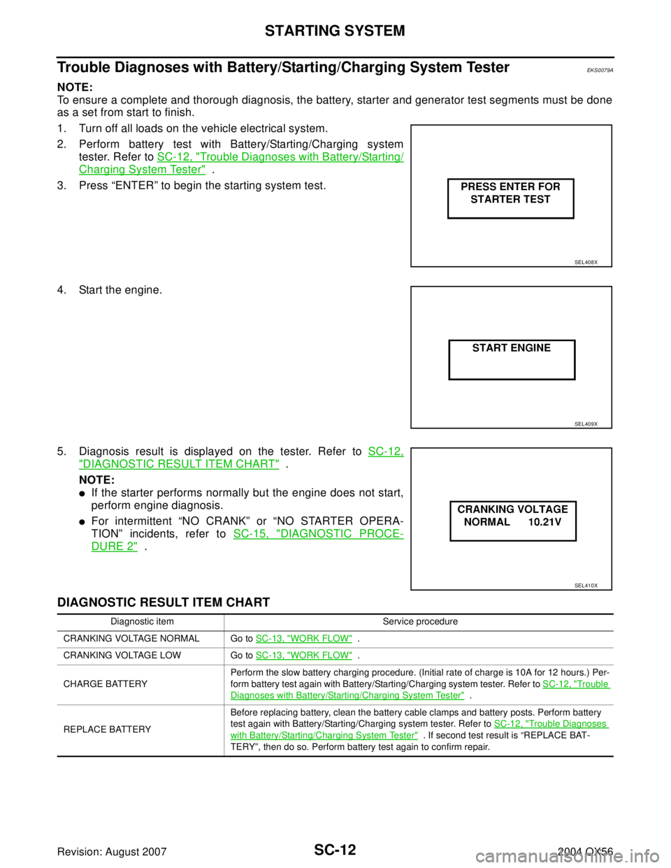
3. Press “ENTER” to begin the starting system test.
4. Start the engine.
5. Diagnosis result is displayed on the tester. Refer to SC-12,
"DIAGNOSTIC RESULT ITEM CHART" .
NOTE:
�If the starter performs normally but the engine does not start,
perform engine diagnosis.
�For intermittent “NO CRANK” or “NO STARTER OPERA-
TION” incidents, refer to SC-15, "
DIAGNOSTIC PROCE-
DURE 2" .
DIAGNOSTIC RESULT ITEM CHART
SEL408X
SEL409X
SEL410X
Diagnostic item Service procedure
CRANKING VOLTAGE NORMAL Go to SC-13, "
WORK FLOW" .
CRANKING VOLTAGE LOW Go to SC-13, "
WORK FLOW" .
CHARGE BATTERYPerform the slow battery charging procedure. (Initial rate of charge is 10A for 12 hours.) Per-
form battery test again with Battery/Starting/Charging system tester. Refer to SC-12, "
Trouble
Diagnoses with Battery/Starting/Charging System Tester" .
REPLACE BATTERYBefore replacing battery, clean the battery cable clamps and battery posts. Perform battery
test again with Battery/Starting/Charging system tester. Refer to SC-12, "
Trouble Diagnoses
with Battery/Starting/Charging System Tester" . If second test result is “REPLACE BAT-
TERY”, then do so. Perform battery test again to confirm repair.
Page 2941 of 3371
SC-20
CHARGING SYSTEM
Revision: August 20072004 QX56
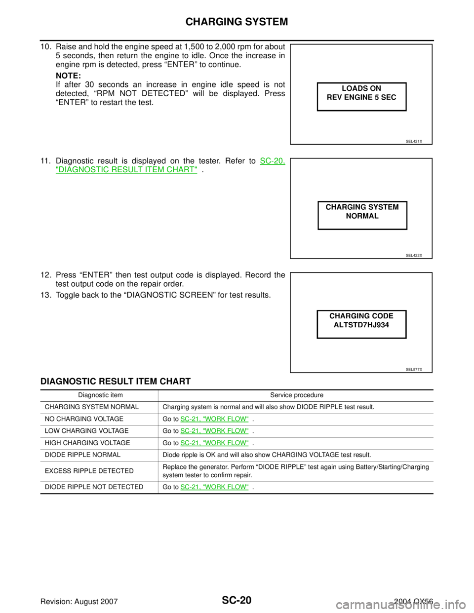
10. Raise and hold the engine speed at 1,500 to 2,000 rpm for about
5 seconds, then return the engine to idle. Once the increase in
engine rpm is detected, press “ENTER” to continue.
NOTE:
If after 30 seconds an increase in engine idle speed is not
detected, “RPM NOT DETECTED” will be displayed. Press
“ENTER” to restart the test.
11. Diagnostic result is displayed on the tester. Refer to SC-20,
"DIAGNOSTIC RESULT ITEM CHART" .
12. Press “ENTER” then test output code is displayed. Record the
test output code on the repair order.
13. Toggle back to the “DIAGNOSTIC SCREEN” for test results.
DIAGNOSTIC RESULT ITEM CHART
SEL421X
SEL422X
SEL577X
Diagnostic item Service procedure
CHARGING SYSTEM NORMAL Charging system is normal and will also show DIODE RIPPLE test result.
NO CHARGING VOLTAGE Go to SC-21, "
WORK FLOW" .
LOW CHARGING VOLTAGE Go to SC-21, "
WORK FLOW" .
HIGH CHARGING VOLTAGE Go to SC-21, "
WORK FLOW" .
DIODE RIPPLE NORMAL Diode ripple is OK and will also show CHARGING VOLTAGE test result.
EXCESS RIPPLE DETECTEDReplace the generator. Perform “DIODE RIPPLE” test again using Battery/Starting/Charging
system tester to confirm repair.
DIODE RIPPLE NOT DETECTED Go to SC-21, "
WORK FLOW" .
Page 2943 of 3371
SC-22
CHARGING SYSTEM
Revision: August 20072004 QX56
DIAGNOSTIC PROCEDURE 1
Check Terminal "3" Circuit
1. CHECK “3” TERMINAL CONNECTION
1. Turn the ignition switch OFF.
2. Check to see if “3” terminal is clean and tight.
OK or NG
OK >> GO TO 2.
NG >> Repair “3” terminal connection. Confirm repair by performing complete Battery/Starting/Charging
system test.
2. CHECK “3” TERMINAL CIRCUIT
1. Disconnect E205 connector from generator.
2. Apply ground to connector E205 terminal 3 (BR/W) with the igni-
tion switch in the ON position.
OK or NG
OK >> GO TO SC-21, "WORK FLOW" .
NG >> Check the following.
�10A fuse [No. 14, located in fuse block (J/B)]
�CHARGE lamp
�Harness for open or short between combination
meter and fuse
�Harness for open or short between combination meter and generator CHARGE lamp should light up.
WKIA2110E
Page 2944 of 3371
CHARGING SYSTEM
SC-23
C
D
E
F
G
H
I
J
L
MA
B
SC
Revision: August 20072004 QX56
DIAGNOSTIC PROCEDURE 2
Check Terminal "1" Circuit
1. CHECK “1” TERMINAL CONNECTION
1. Turn the ignition switch OFF.
2. Check to see if “1” terminal is clean and tight.
OK or NG
OK >> GO TO 2.
NG >> Repair “1” terminal connection. Confirm repair by performing complete Battery/Starting/Charging
system test.
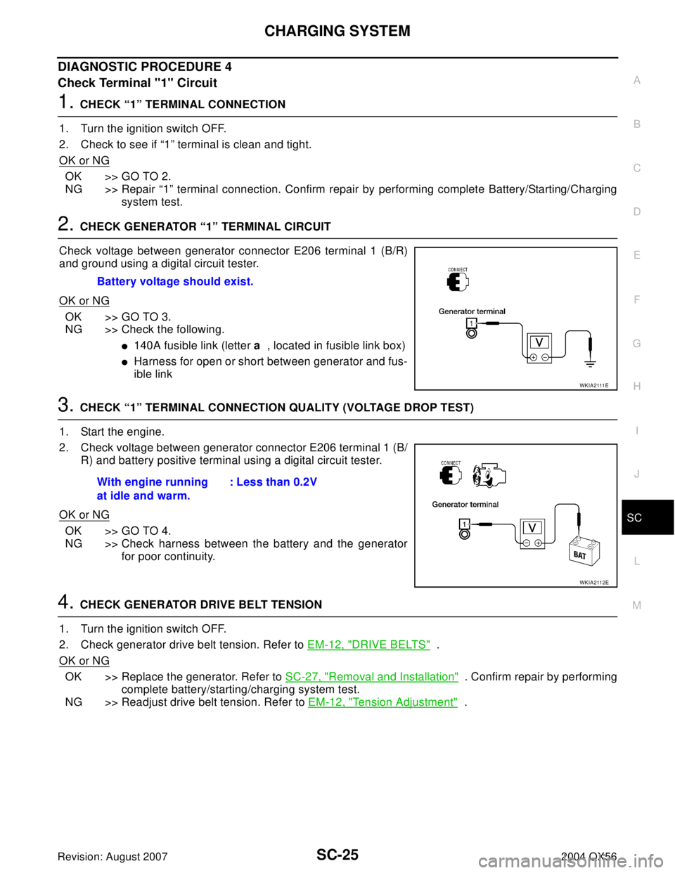
2. CHECK GENERATOR “1” TERMINAL CIRCUIT
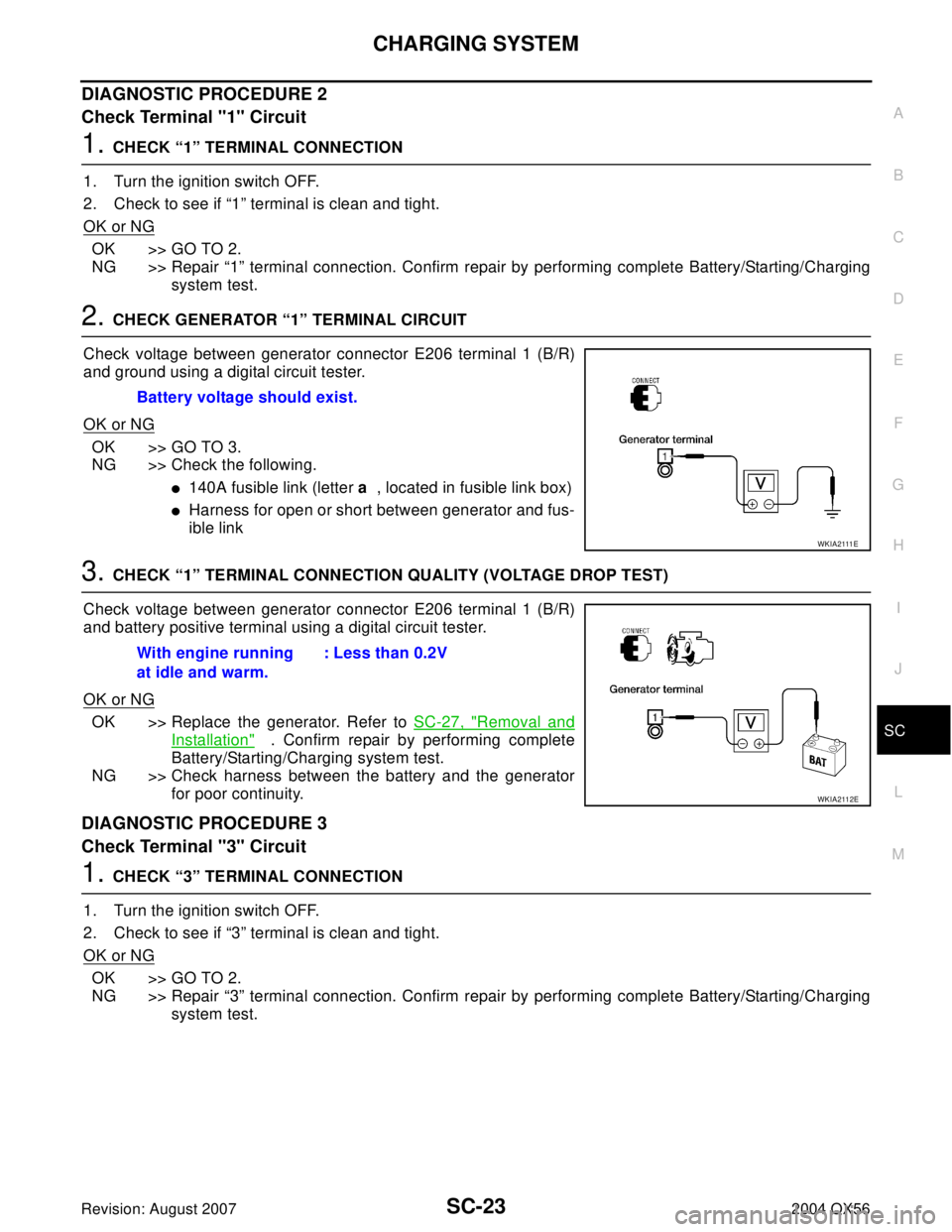
Check voltage between generator connector E206 terminal 1 (B/R)
and ground using a digital circuit tester.
OK or NG
OK >> GO TO 3.
NG >> Check the following.
�140A fusible link (letter a , located in fusible link box)
�Harness for open or short between generator and fus-
ible link
3. CHECK “1” TERMINAL CONNECTION QUALITY (VOLTAGE DROP TEST)
Check voltage between generator connector E206 terminal 1 (B/R)
and battery positive terminal using a digital circuit tester.
OK or NG
OK >> Replace the generator. Refer to SC-27, "Removal and
Installation" . Confirm repair by performing complete
Battery/Starting/Charging system test.
NG >> Check harness between the battery and the generator
for poor continuity.
DIAGNOSTIC PROCEDURE 3
Check Terminal "3" Circuit
1. CHECK “3” TERMINAL CONNECTION
1. Turn the ignition switch OFF.
2. Check to see if “3” terminal is clean and tight.
OK or NG
OK >> GO TO 2.
NG >> Repair “3” terminal connection. Confirm repair by performing complete Battery/Starting/Charging
system test. Battery voltage should exist.
W K I A 2111 E
With engine running
at idle and warm.: Less than 0.2V
WKIA2112E
Page 2945 of 3371
SC-24
CHARGING SYSTEM
Revision: August 20072004 QX56
2. CHECK “3” TERMINAL CIRCUIT
1. Disconnect E205 connector from generator.
2. Apply ground to connector E205 terminal 3 (BR/W) with the igni-
tion switch in the ON position.
OK or NG
OK >> Replace the generator. Refer to SC-27, "Removal and
Installation" . Confirm repair by performing complete
battery/starting/charging system test.
NG >> Check the following.
�10A fuse [No. 14, located in fuse block (J/B)]
�CHARGE lamp
�Harness for open or short between combination meter and fuse
�Harness for open or short between combination meter and generator CHARGE lamp should light up.
WKIA2110E
Page 2946 of 3371
CHARGING SYSTEM
SC-25
C
D
E
F
G
H
I
J
L
MA
B
SC
Revision: August 20072004 QX56
DIAGNOSTIC PROCEDURE 4
Check Terminal "1" Circuit
1. CHECK “1” TERMINAL CONNECTION
1. Turn the ignition switch OFF.
2. Check to see if “1” terminal is clean and tight.
OK or NG
OK >> GO TO 2.
NG >> Repair “1” terminal connection. Confirm repair by performing complete Battery/Starting/Charging
system test.
2. CHECK GENERATOR “1” TERMINAL CIRCUIT
Check voltage between generator connector E206 terminal 1 (B/R)
and ground using a digital circuit tester.
OK or NG
OK >> GO TO 3.
NG >> Check the following.
�140A fusible link (letter a , located in fusible link box)
�Harness for open or short between generator and fus-
ible link
3. CHECK “1” TERMINAL CONNECTION QUALITY (VOLTAGE DROP TEST)
1. Start the engine.
2. Check voltage between generator connector E206 terminal 1 (B/
R) and battery positive terminal using a digital circuit tester.
OK or NG
OK >> GO TO 4.
NG >> Check harness between the battery and the generator
for poor continuity.
4. CHECK GENERATOR DRIVE BELT TENSION
1. Turn the ignition switch OFF.
2. Check generator drive belt tension. Refer to EM-12, "
DRIVE BELTS" .
OK or NG
OK >> Replace the generator. Refer to SC-27, "Removal and Installation" . Confirm repair by performing
complete battery/starting/charging system test.
NG >> Readjust drive belt tension. Refer to EM-12, "
Tension Adjustment" . Battery voltage should exist.
W K I A 2111 E
With engine running
at idle and warm.: Less than 0.2V
WKIA2112E
Page 2947 of 3371
SC-26
CHARGING SYSTEM
Revision: August 20072004 QX56
DIAGNOSTIC PROCEDURE 5
Check Terminal "4" Circuit
1. CHECK “4” TERMINAL CONNECTION
1. Turn the ignition switch OFF.
2. Check to see if “4” terminal is clean and tight.
OK or NG
OK >> GO TO 2.
NG >> Repair “4” terminal connection. Confirm repair by performing complete Battery/Starting/Charging
system test.
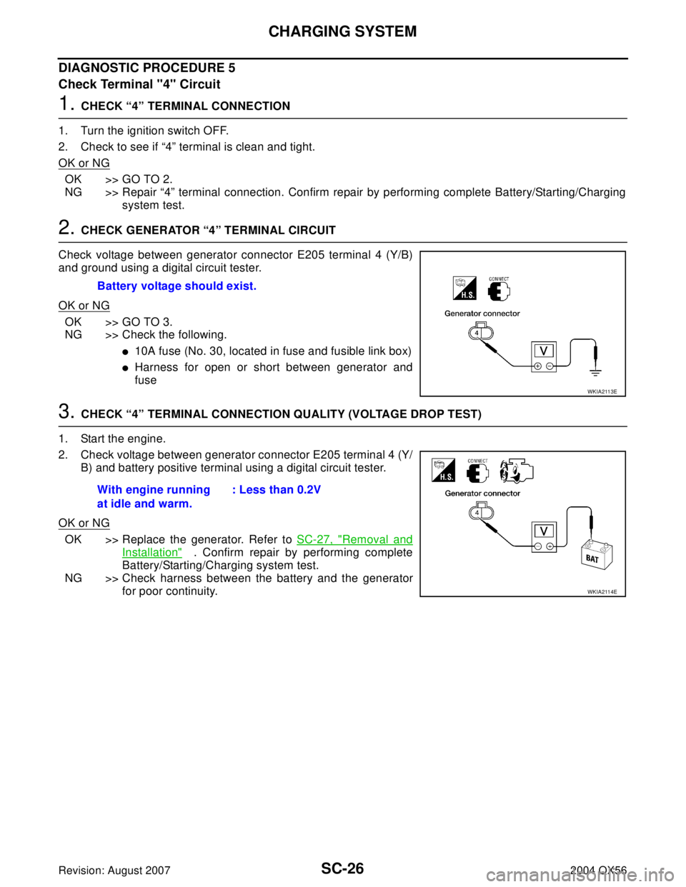
2. CHECK GENERATOR “4” TERMINAL CIRCUIT
Check voltage between generator connector E205 terminal 4 (Y/B)
and ground using a digital circuit tester.
OK or NG
OK >> GO TO 3.
NG >> Check the following.
�10A fuse (No. 30, located in fuse and fusible link box)
�Harness for open or short between generator and
fuse
3. CHECK “4” TERMINAL CONNECTION QUALITY (VOLTAGE DROP TEST)
1. Start the engine.
2. Check voltage between generator connector E205 terminal 4 (Y/
B) and battery positive terminal using a digital circuit tester.
OK or NG
OK >> Replace the generator. Refer to SC-27, "Removal and
Installation" . Confirm repair by performing complete
Battery/Starting/Charging system test.
NG >> Check harness between the battery and the generator
for poor continuity. Battery voltage should exist.
WKIA2113E
With engine running
at idle and warm.: Less than 0.2V
WKIA2114E