Page 1274 of 3371

TROUBLE DIAGNOSIS
EC-83
C
D
E
F
G
H
I
J
K
L
MA
EC
Revision: August 20072004 QX56
15. CHECK IGNITION TIMING AGAIN
1. Run engine at idle.
2. Check ignition timing with a timing light.
OK or NG
OK >>INSPECTION END
NG >> GO TO 16.
16. CHECK TIMING CHAIN INSTALLATION
Check timing chain installation. Refer to EM-35, "
TIMING CHAIN" .
OK or NG
OK >> GO TO 17.
NG >> 1. Repair the timing chain installation.
2. GO TO 4.
17. DETECT MALFUNCTIONING PART
Check the following.
�Check camshaft position sensor (PHASE) and circuit. Refer to EC-261 .
�Check crankshaft position sensor (POS) and circuit. Refer to EC-255 .
OK or NG
OK >> GO TO 18.
NG >> 1. Repair or replace.
2. GO TO 4.
18. CHECK ECM FUNCTION
1. Substitute another known-good ECM to check ECM function. (ECM may be the cause of an incident, but
this is a rare case.)
2. Perform initialization of IVIS (NATS) system and registration of all IVIS (NATS) ignition key IDs. Refer to
BL-138, "
IVIS (INFINITI VEHICLE IMMOBILIZER SYSTEM-NATS)" .
>> GO TO 4. 15 ± 5° BTDC (in P or N position)
BBIA0379E
Page 1534 of 3371
DTC P0506 ISC SYSTEM
EC-343
C
D
E
F
G
H
I
J
K
L
MA
EC
Revision: August 20072004 QX56
Diagnostic ProcedureUBS00H6K
1. CHECK INTAKE AIR LEAK
1. Start engine and let it idle.
2. Listen for an intake air leak after the mass air flow sensor.
OK or NG
OK >> GO TO 2.
NG >> Discover air leak location and repair.
2. REPLACE ECM
1. Stop engine.
2. Replace ECM.
3. Perform initialization of IVIS(NATS) system and registration of all IVIS(NATS) ignition key IDs. Refer to
BL-140, "
ECM Re-communicating Function" .
4. Perform EC-44, "
Accelerator Pedal Released Position Learning" .
5. Perform EC-44, "
Throttle Valve Closed Position Learning" .
6. Perform EC-44, "
Idle Air Volume Learning" .
>>INSPECTION END
Page 1536 of 3371
DTC P0507 ISC SYSTEM
EC-345
C
D
E
F
G
H
I
J
K
L
MA
EC
Revision: August 20072004 QX56
Diagnostic ProcedureUBS00H6O
1. CHECK PCV HOSE CONNECTION
Confirm that PCV hose is connected correctly.
OK or NG
OK >> GO TO 2.
NG >> Repair or replace.
2. CHECK INTAKE AIR LEAK
1. Start engine and let it idle.
2. Listen for an intake air leak after the mass air flow sensor.
OK or NG
OK >> GO TO 3.
NG >> Discover air leak location and repair.
3. REPLACE ECM
1. Stop engine.
2. Replace ECM.
3. Perform initialization of IVIS(NATS) system and registration of all IVIS(NATS) ignition key IDs. Refer to
BL-140, "
ECM Re-communicating Function" .
4. Perform EC-44, "
Accelerator Pedal Released Position Learning" .
5. Perform EC-44, "
Throttle Valve Closed Position Learning" .
6. Perform EC-44, "
Idle Air Volume Learning" .
>>INSPECTION END
Page 1544 of 3371
DTC P0605 ECM
EC-353
C
D
E
F
G
H
I
J
K
L
MA
EC
Revision: August 20072004 QX56
2. REPLACE ECM
1. Replace ECM.
2. Perform initialization of IVIS(NATS) system and registration of all IVIS(NATS) ignition key IDs. Refer to
BL-140, "
ECM Re-communicating Function" .
3. Perform EC-44, "
Accelerator Pedal Released Position Learning" .
4. Perform EC-44, "
Throttle Valve Closed Position Learning" .
5. Perform EC-44, "
Idle Air Volume Learning" .
>>INSPECTION END
Page 1555 of 3371
EC-364Revision: August 2007
DTC P1065 ECM POWER SUPPLY
2004 QX56
4. PERFORM DTC CONFIRMATION PROCEDURE
With CONSULT-II
1. Turn ignition switch ON.
2. Select “SELF DIAG RESULTS” mode with CONSULT-II.
3. Touch “ERASE”.
4.Perform DTC Confirmation Procedure.
See EC-361, "
DTC Confirmation Procedure" .
5. Is the 1st trip DTC P1065 displayed again?
With GST
1. Turn ignition switch ON.
2. Select MODE 4 with GST.
3. Touch “ERASE”.
4.Perform DTC Confirmation Procedure.
See EC-361, "
DTC Confirmation Procedure" .
5. Is the 1st trip DTC P1065 displayed again?
Ye s o r N o
Yes >> GO TO 5.
No >>INSPECTION END
5. REPLACE ECM
1. Replace ECM.
2. Perform initialization of IVIS(NATS) system and registration of all IVIS(NATS) ignition key IDs. Refer to
BL-140, "
ECM Re-communicating Function" .
3. Perform EC-44, "
Accelerator Pedal Released Position Learning" .
4. Perform EC-44, "
Throttle Valve Closed Position Learning" .
5. Perform EC-44, "
Idle Air Volume Learning" .
>>INSPECTION END
Page 1922 of 3371
TIMING CHAIN
EM-39
C
D
E
F
G
H
I
J
K
L
MA
EM
Revision: August 20072004 QX56
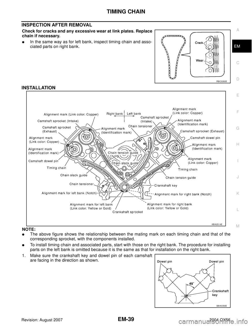
INSPECTION AFTER REMOVAL
Check for cracks and any excessive wear at link plates. Replace
chain if necessary.
�In the same way as for left bank, inspect timing chain and asso-
ciated parts on right bank.
INSTALLATION
NOTE:
�The above figure shows the relationship between the mating mark on each timing chain and that of the
corresponding sprocket, with the components installed.
�To install timing chain and associated parts, start with those on the right bank. The procedure for installing
parts on the left bank is omitted because it is the same as that for installation on the right bank.
1. Make sure the crankshaft key and dowel pin of each camshaft
are facing in the direction as shown.
PBIC0282E
KBIA2514E
SBIA0356E
Page 1923 of 3371

EM-40Revision: August 2007
TIMING CHAIN
2004 QX56
2. Install camshaft sprockets.
�Install intake and exhaust camshaft sprocket by selectively
using the groove of dowel pin according to the bank (common
part used for both banks).
�Lock the hexagonal part of camshaft in the same way as for
removal, and tighten bolts.
3. Install crankshaft sprockets for both banks.
�Install each crankshaft sprocket so that its flange side (the
larger diameter side without teeth) faces in the direction as
shown.
NOTE:
The same parts are used but facing directions are different.
4. Install timing chains and associated parts.
�Align the mating mark on each sprocket and the timing chain for installation.
CAUTION:
�Before installing chain tensioner, it is possible to change the position of mating mark on tim-
ing chain and each sprocket. After the mating marks are aligned, keep them aligned by hold-
ing them by hand.
�Install slack guides and tension guides onto correct side by checking with identification mark on sur-
face.
�Install chain tensioner with plunger locked in with stopper pin.
CAUTION:
�Before and after the installation of chain tensioner, make sure that the mating mark on timing
chain is not out of alignment.
�After installing chain tensioner, remove the stopper pin to release tensioner. Make sure ten-
sioner is released.
�To avoid chain-link skipping of timing chain, never move crankshaft or camshafts until front
cover is installed.
5. In the same way as for right bank, install the timing chain and associated parts on the left side.
6. Install the oil pump.
7. Install the oil pump drive spacer as follows:
�Install so that the front mark on the front edge of oil pump
drive spacer faces the front of the engine.
�Insert oil pump drive spacer according to the directions of the
crankshaft key and the two flat surfaces of oil pump inner
rotor.
�If the positional relationship does not allow the insertion,
rotate oil pump inner rotor to allow the oil pump drive spacer
to be inserted.
KBIA2480E
KBIA2515E
KBIA2490E
Page 1925 of 3371

EM-42Revision: August 2007
TIMING CHAIN
2004 QX56
d. Install bolts in the numerical order shown.
e. Tighten to the specified torque.
CAUTION:
Be sure to wipe off any excessive liquid gasket leaking onto
surface mating with oil pan.
11. Install chain case cover (right bank) and (left bank) as follows:
a. Apply liquid gasket as shown.
Use Genuine RTV Silicone Sealant or equivalent. Refer to
GI-45, "
Recommended Chemical Products and Sealants".
CAUTION:
Both the start and end of application of liquid gasket should
be crossed at an invisible position after attaching the chain
case cover.
b. Install bolts in the numerical order shown.
12. Install the crankshaft pulley.
�Install the key of the crankshaft.
�Insert the pulley by lightly tapping it.
CAUTION:
Do not tap pulley on the side surface where belt is installed (outer circumference).
13. Tighten the crankshaft pulley bolt.
�Lock crankshaft using suitable tool, then tighten the bolt.
�Perform the following steps for angular tightening:
a. Apply engine oil onto threaded parts of bolt and seating area.
b. Select one most visible notch of the four on bolt flange. Corre-
sponding to the selected notch, put a mating mark (such as
paint) on crankshaft pulley.
14. Rotate crankshaft pulley in normal direction (clockwise when
viewed from engine front) to check for parts interference.
15. Installation of the remaining components is in the reverse order
of removal.M6 × 50 mm (1.97 in) : No. 1, 20, 25, 26, 27
M6 × 80 mm (3.15 in) : No. 4, 5, 7
M6 × 20 mm (0.79 in) : Except the above
KBIA2478E
KBIA2481E
WBIA0468E
Crankshaft pulley bolt torque
Step 1 : 93.1 N·m (9.5 kg-m, 69 ft-lb)
Step 2 : additional 90° (angle tightening)
KBIA2519E


 system and registration of all IVIS(NATS) ignition")