Page 1998 of 3371

FAX-1
FRONT AXLE
D DRIVELINE/AXLE
CONTENTS
C
E
F
G
H
I
J
K
L
M
SECTION FA X
A
B
FA X
Revision: August 20072004 QX56 PRECAUTIONS .......................................................... 2
Precautions .............................................................. 2
PREPARATION ........................................................... 3
Special Service Tools ............................................... 3
Commercial Service Tools ........................................ 3
NOISE, VIBRATION, AND HARSHNESS (NVH)
TROUBLESHOOTING ................................................ 4
NVH Troubleshooting Chart ..................................... 4
WHEEL HUB .............................................................. 5
On-Vehicle Inspection and Service .......................... 5
WHEEL BEARING INSPECTION ......................... 5
Removal and Installation .......................................... 5
REMOVAL ............................................................. 5
INSPECTION AFTER REMOVAL ......................... 6
INSTALLATION ..................................................... 6DRIVE SHAFT ............................................................. 7
Removal and Installation .......................................... 7
REMOVAL ............................................................. 7
INSPECTION AFTER REMOVAL ......................... 7
INSTALLATION ..................................................... 8
Disassembly and Assembly ...................................... 8
DISASSEMBLY ..................................................... 8
INSPECTION AFTER DISASSEMBLY .................. 9
ASSEMBLY ......................................................... 10
SERVICE DATA AND SPECIFICATIONS (SDS) ...... 13
Wheel Bearing ........................................................ 13
Drive Shaft .............................................................. 13
Page 1999 of 3371
FAX-2
PRECAUTIONS
Revision: August 20072004 QX56
PRECAUTIONSPFP:00001
PrecautionsEDS001AG
Observe the following precautions when disassembling and servicing the wheel hub and drive shafts.
�Perform work in a location which is as dust-free as possible.
�Before disassembling and servicing, clean the outside of parts.
�Prevention of the entry of foreign objects must be taken into account during disassembly of the compo-
nent parts.
�Disassembled parts must be carefully reassembled in the correct order. If work is interrupted, a clean
cover must be placed over parts.
�Paper shop cloths must be used. Fabric shop cloths must not be used because of the danger of lint adher-
ing to parts.
�Disassembled parts (except for rubber parts) should be cleaned with a suitable solvent which shall be
removed by blowing with air or wiping with paper shop cloths.
Page 2001 of 3371
 TROUBLESHOOTING
Revision: August 20072004 QX56
NOISE, VIBRATION, AND HARSHNESS (NVH) TROUBLESHOOTINGPFP:00003
NVH Troubleshooting ChartEDS001AI
Use the char")
FAX-4
NOISE, VIBRATION, AND HARSHNESS (NVH) TROUBLESHOOTING
Revision: August 20072004 QX56
NOISE, VIBRATION, AND HARSHNESS (NVH) TROUBLESHOOTINGPFP:00003
NVH Troubleshooting ChartEDS001AI
Use the chart below to help you find the cause of the symptom. If necessary, repair or replace these parts.
×: ApplicableReference page
FAX -1 3FA X - 7FA X - 5FA X - 5FA X - 7FA X - 5
PR-3, "
NVH Troubleshooting Chart
"
FFD-7, "
NVH Troubleshooting Chart
"
FSU-4, "
NVH Troubleshooting Chart
"
WT-3, "
NVH Troubleshooting Chart
"
WT-3, "
NVH Troubleshooting Chart
"
BR-5, "
NVH Troubleshooting Chart
"
PS-5, "
NVH Troubleshooting Chart
"
Possible cause and SUSPECTED PARTS
Excessive joint angle
Joint sliding resistance
Imbalance
Improper installation, looseness
Parts interference
Wheel bearing damage
PROPELLER SHAFT
FRONT FINAL DRIVE
SUSPENSION
TIRES
ROAD WHEEL
BRAKES
STEERING
SymptomNoise×× ×× ×××××××
Shake× ××× × ×××××
Vibration××××× × ×× ×
Shimmy× ×× ×××××
Shudder×××× ×××××
Poor quality ride or
handling××× ×××
Page 2002 of 3371
 of each")
WHEEL HUB
FAX-5
C
E
F
G
H
I
J
K
L
MA
B
FA X
Revision: August 20072004 QX56
WHEEL HUBPFP:43202
On-Vehicle Inspection and ServiceEDS001AJ
Make sure the mounting conditions (looseness, backlash) of each component and component status (wear,
damage) are normal.
WHEEL BEARING INSPECTION
�Move wheel hub in the axial direction by hand. Make sure there
is no looseness of wheel bearing.
�Rotate wheel hub and make sure there is no unusual noise or
other irregular conditions. If there are any irregular conditions,
replace wheel hub and bearing assembly.
Removal and InstallationEDS001AK
REMOVAL
1. Remove wheel and tire using power tool.
2. Remove engine under cover using power tool.
3. Without disassembling the hydraulic lines, remove caliper torque member bolts using power tool. Then
reposition brake caliper aside with wire. Refer to BR-22, "
Removal and Installation of Brake Caliper and
Disc Rotor" .
NOTE:
Do not press brake pedal while brake caliper is removed.Axial end play limit : 0.05 mm (0.002 in) or less
SM A57 1A
1. Disc rotor 2. Wheel hub and bearing assembly 3. Wheel stud
4. Splash guard 5. Steering knuckle
WDIA0043E
Page 2003 of 3371

FAX-6
WHEEL HUB
Revision: August 20072004 QX56
4. Put alignment mark on disc rotor and wheel hub and bearing
assembly, then remove disc rotor.
5. Remove cotter pin, then remove lock nut from drive shaft using power tool. Refer to FA X -7 , "
Removal and
Installation" .
6. Remove drive shaft from wheel hub and bearing assembly. Refer to FAX-7, "
Removal and Installation" .
7. Remove wheel sensor. Refer to BRC-64, "
Removal and Installation" .
�Inspect the wheel sensor O-ring, replace the wheel sensor assembly if damaged.
�Clean the wheel sensor hole and mounting surface with a suitable brake cleaner and clean lint-free
shop rag. Be careful that dirt and debris do not enter the axle bearing area.
�Apply a coat of suitable grease to the wheel sensor O-ring and mounting hole.
CAUTION:
Do not pull on the wheel sensor harness.
8. Remove wheel hub and bearing assembly bolts using power tool.
9. Remove splash guard and wheel hub and bearing assembly from steering knuckle.
INSPECTION AFTER REMOVAL
Check for deformity, cracks and damage on each part, replace if necessary.
INSTALLATION
Installation is in the reverse order of removal.
�Use new bolts when installing the wheel hub and bearing assembly.
�When installing disc rotor on wheel hub and bearing assembly,
position the disc rotor according to alignment mark.
(When not using the alignment mark, refer to BR-22, "
Removal
and Installation of Brake Caliper and Disc Rotor" .)
�When installing wheel and tire. Refer to WT-6, "Rotation" .
WDIA0044E
WDIA0044E
Page 2004 of 3371

DRIVE SHAFT
FAX-7
C
E
F
G
H
I
J
K
L
MA
B
FA X
Revision: August 20072004 QX56
DRIVE SHAFTPFP:39100
Removal and InstallationEDS001B5
REMOVAL
1. Remove wheel and tire using power tool.
2. Remove engine under cover using power tool.
3. Remove wheel sensor harness from mount on knuckle.
CAUTION:
Do not pull on wheel sensor harness.
4. Without disassembling the hydraulic lines, remove brake caliper using power tool. Reposition it aside with
wire. Refer to BR-22, "
Removal and Installation of Brake Caliper and Disc Rotor" .
NOTE:
Avoid depressing brake pedal while brake caliper is removed.
5. Remove coil spring and shock absorber assembly using power tool. Refer to FSU-10, "
Removal and
Installation" .
6. Separate upper link ball joint stud from steering knuckle using
Tool.
�Support lower link with jack.
7. Remove cotter pin, then remove drive shaft nut.
8. Remove drive shaft mounting bolts from front final drive.
9. Remove drive shaft from wheel hub and bearing assembly.
CAUTION:
�When removing drive shaft, do not apply an excessive
angle to drive shaft joint. Also be careful not to exces-
sively extend slide joint.
INSPECTION AFTER REMOVAL
�Move joint up, down, left, right, and in axial direction. Check for any rough movement or significant loose-
ness.
�Check boot for cracks or other damage, and for grease leakage.
�If damaged, disassemble drive shaft to verify damage, and
repair or replace as necessary.
1. Cotter pin 2. Drive shaft nut 3. Drive shaft
LDIA0159E
Tool number : ST29020001 (J-24319-01)
LEIA0095E
RAA0030D
Page 2005 of 3371
FAX-8
DRIVE SHAFT
Revision: August 20072004 QX56
INSTALLATION
Installation is in the reverse order of removal.
�Tighten wheel nuts to specification. Refer to WT-6, "Rotation" .
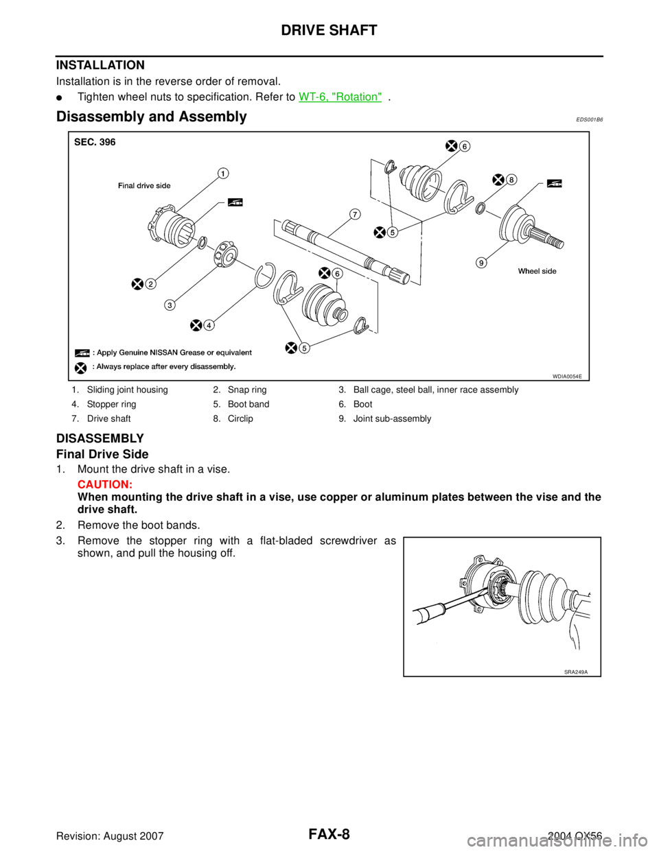
Disassembly and AssemblyEDS001B6
DISASSEMBLY
Final Drive Side
1. Mount the drive shaft in a vise.
CAUTION:
When mounting the drive shaft in a vise, use copper or aluminum plates between the vise and the
drive shaft.
2. Remove the boot bands.
3. Remove the stopper ring with a flat-bladed screwdriver as
shown, and pull the housing off.
1. Sliding joint housing 2. Snap ring 3. Ball cage, steel ball, inner race assembly
4. Stopper ring 5. Boot band 6. Boot
7. Drive shaft 8. Circlip 9. Joint sub-assembly
WDIA0054E
SRA2 49 A
Page 2006 of 3371

DRIVE SHAFT
FAX-9
C
E
F
G
H
I
J
K
L
MA
B
FA X
Revision: August 20072004 QX56
4. Remove the snap ring, then remove the ball cage, steel ball,
inner race assembly from the drive shaft.
5. Remove the boot from the drive shaft.
6. Remove any old grease on the housing using paper towels.
Wheel Side
1. Mount the drive shaft in a vise.
CAUTION:
When mounting the drive shaft in a vise, use copper or aluminum plates between the vise and the
drive shaft.
2. Remove the boot bands, then remove the boot from the joint sub-assembly.
3. Screw a suitable drive shaft puller 30 mm (1.18 in) or more into
the threaded part of the joint sub-assembly. Pull the joint sub-
assembly off of the drive shaft as shown.
NOTE:
Align the sliding hammer and drive shaft and remove the joint
sub-assembly by pulling directly.
CAUTION:
�If the joint sub-assembly cannot be removed after five or
more attempts, replace the drive shaft and joint sub-
assembly as a set.
4. Remove the boot from the drive shaft.
5. Remove the circlip from the drive shaft.
6. While rotating the ball cage, remove any old grease from the joint sub-assembly using paper towels.
INSPECTION AFTER DISASSEMBLY
Drive Shaft
�Replace the drive shaft if there is any runout, cracking, or other damage.
Joint Sub-assembly
�Check for any rough rotation or unusual axial looseness.
�Clean any foreign material from inside the joint sub-assembly.
�Check for any compression scars, cracks, or fractures.
CAUTION:
If any defective conditions are found in the joint sub-assembly components, replace the entire
joint sub-assembly.
Sliding Joint Side Housing
�Check for any compression scars, cracks, fractures, or unusual wear on the ball rolling surface.
�Check for any damage to the drive shaft screws.
�Check for any deformation of the boot installation components.
Ball Cage
�Check the sliding surface for any compression scars, cracks, or fractures.
SFA514A
SDIA0606E