Page 3636 of 4449
FRONT FOG LAMP
LT-81
C
D
E
F
G
H
I
J
L
MA
B
LT
Revision: 2004 November 2004 FX35/FX45
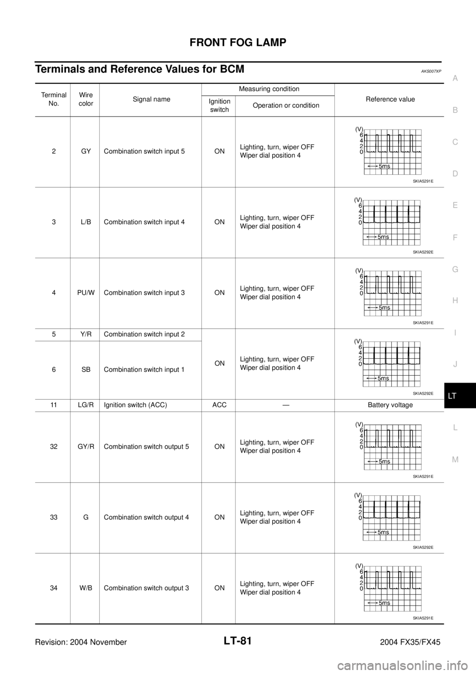
Terminals and Reference Values for BCMAKS007XP
Te r m i n a l
No.Wire
colorSignal nameMeasuring condition
Reference value
Ignition
switchOperation or condition
2 GY Combination switch input 5 ONLighting, turn, wiper OFF
Wiper dial position 4
3 L/B Combination switch input 4 ONLighting, turn, wiper OFF
Wiper dial position 4
4 PU/W Combination switch input 3 ONLighting, turn, wiper OFF
Wiper dial position 4
5 Y/R Combination switch input 2
ONLighting, turn, wiper OFF
Wiper dial position 4
6 SB Combination switch input 1
11 LG/R Ignition switch (ACC) ACC — Battery voltage
32 GY/R Combination switch output 5 ONLighting, turn, wiper OFF
Wiper dial position 4
33 G Combination switch output 4 ONLighting, turn, wiper OFF
Wiper dial position 4
34 W/B Combination switch output 3 ONLighting, turn, wiper OFF
Wiper dial position 4
SKIA5291E
SKIA5292E
SKIA5291E
SKIA5292E
SKIA5291E
SKIA5292E
SKIA5291E
Page 3637 of 4449
LT-82
FRONT FOG LAMP
Revision: 2004 November 2004 FX35/FX45
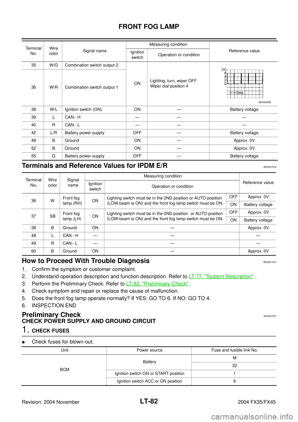
Terminals and Reference Values for IPDM E/RAKS007CN
How to Proceed With Trouble DiagnosisAKS007CO
1. Confirm the symptom or customer complaint.
2. Understand operation description and function description. Refer to LT- 7 7 , "
System Description" .
3. Perform the Preliminary Check. Refer to LT- 8 2 , "
Preliminary Check" .
4. Check symptom and repair or replace the cause of malfunction.
5. Does the front fog lamp operate normally? If YES: GO TO 6. If NO: GO TO 4.
6. INSPECTION END
Preliminary CheckAKS007CP
CHECK POWER SUPPLY AND GROUND CIRCUIT
1. CHECK FUSES
�Check fuses for blown-out.
35 W/G Combination switch output 2
ONLighting, turn, wiper OFF
Wiper dial position 4
36 W/R Combination switch output 1
38 W/L Ignition switch (ON) ON — Battery voltage
39 L CAN− H—— —
40 R CAN− L—— —
42 L/R Battery power supply OFF — Battery voltage
49 B Ground ON — Approx. 0V
52 B Ground ON — Approx. 0V
55 G Battery power supply OFF — Battery voltage Terminal
No.Wire
colorSignal nameMeasuring condition
Reference value
Ignition
switchOperation or condition
SKIA5292E
Terminal
No.Wire
colorSignal
nameMeasuring condition
Reference value
Ignition
switchOperation or condition
36 WFront fog
lamp (RH) ONLighting switch must be in the 2ND position or AUTO position
(LOW beam is ON) and the front fog lamp switch must be ON.OFF Approx. 0V
ON Battery voltage
37 SBFront fog
lamp (LH)ONLighting switch must be in the 2ND position or AUTO position
(LOW beam is ON) and the front fog lamp switch must be ON.OFF Approx. 0V
ON Battery voltage
38 B Ground ON — Approx. 0V
48 L CAN− H— — —
49 R CAN− L— — —
60 B Ground ON — Approx. 0V
Unit Power source Fuse and fusible link No.
BCMBatteryM
22
Ignition switch ON or START position 1
Ignition switch ACC or ON position 6
Page 3638 of 4449
FRONT FOG LAMP
LT-83
C
D
E
F
G
H
I
J
L
MA
B
LT
Revision: 2004 November 2004 FX35/FX45
Refer to LT-79, "Wiring Diagram — F/FOG —" .
OK or NG
OK >> GO TO 2.
NG >> If fuse is blown, be sure to eliminate cause of malfunction before installing new fuse. Refer to PG-
3, "POWER SUPPLY ROUTING CIRCUIT" .
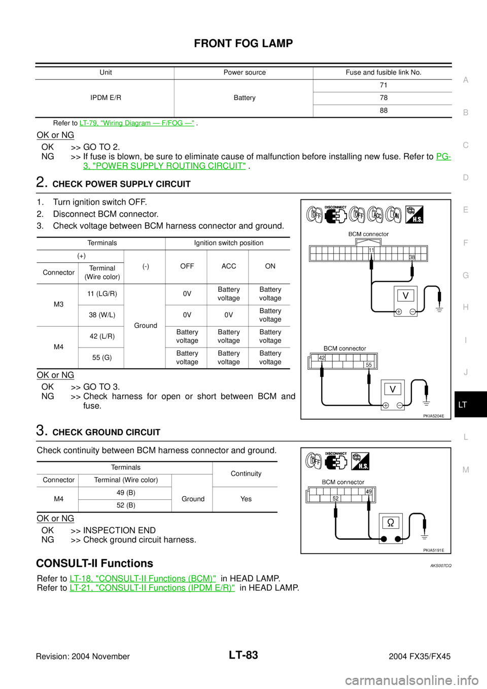
2. CHECK POWER SUPPLY CIRCUIT
1. Turn ignition switch OFF.
2. Disconnect BCM connector.
3. Check voltage between BCM harness connector and ground.
OK or NG
OK >> GO TO 3.
NG >> Check harness for open or short between BCM and
fuse.
3. CHECK GROUND CIRCUIT
Check continuity between BCM harness connector and ground.
OK or NG
OK >> INSPECTION END
NG >> Check ground circuit harness.
CONSULT-II FunctionsAKS007CQ
Refer to LT- 1 8 , "CONSULT-II Functions (BCM)" in HEAD LAMP.
Refer to LT- 2 1 , "
CONSULT-II Functions (IPDM E/R)" in HEAD LAMP.
IPDM E/R Battery71
78
88 Unit Power source Fuse and fusible link No.
Terminals Ignition switch position
(+)
(-) OFF ACC ON
ConnectorTerminal
(Wire color)
M311 (LG/R)
Ground0VBattery
voltageBattery
voltage
38 (W/L) 0V 0VBattery
voltage
M442 (L/R)Battery
voltageBattery
voltageBattery
voltage
55 (G)Battery
voltageBattery
voltageBattery
voltage
PKIA5204E
Terminals
Continuity
Connector Terminal (Wire color)
M449 (B)
Ground Yes
52 (B)
PKIA5191E
Page 3640 of 4449
FRONT FOG LAMP
LT-85
C
D
E
F
G
H
I
J
L
MA
B
LT
Revision: 2004 November 2004 FX35/FX45
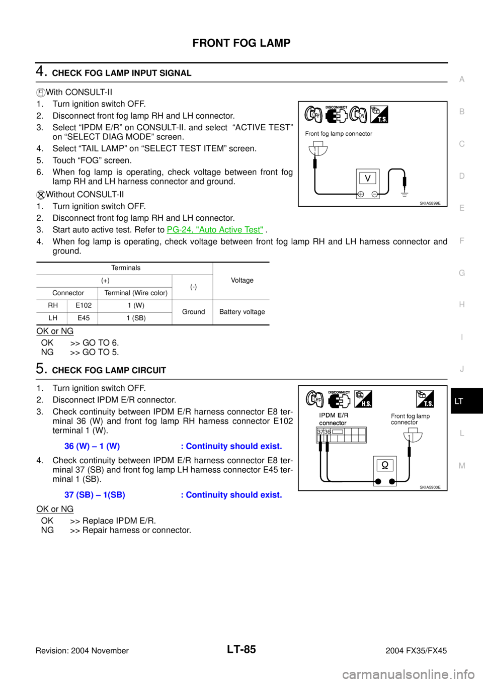
4. CHECK FOG LAMP INPUT SIGNAL
With CONSULT-II
1. Turn ignition switch OFF.
2. Disconnect front fog lamp RH and LH connector.
3. Select “IPDM E/R” on CONSULT-II. and select “ACTIVE TEST”
on “SELECT DIAG MODE” screen.
4. Select “TAIL LAMP” on “SELECT TEST ITEM” screen.
5. Touch “FOG” screen.
6. When fog lamp is operating, check voltage between front fog
lamp RH and LH harness connector and ground.
Without CONSULT-II
1. Turn ignition switch OFF.
2. Disconnect front fog lamp RH and LH connector.
3. Start auto active test. Refer to PG-24, "
Auto Active Test" .
4. When fog lamp is operating, check voltage between front fog lamp RH and LH harness connector and
ground.
OK or NG
OK >> GO TO 6.
NG >> GO TO 5.
5. CHECK FOG LAMP CIRCUIT
1. Turn ignition switch OFF.
2. Disconnect IPDM E/R connector.
3. Check continuity between IPDM E/R harness connector E8 ter-
minal 36 (W) and front fog lamp RH harness connector E102
terminal 1 (W).
4. Check continuity between IPDM E/R harness connector E8 ter-
minal 37 (SB) and front fog lamp LH harness connector E45 ter-
minal 1 (SB).
OK or NG
OK >> Replace IPDM E/R.
NG >> Repair harness or connector.
Terminals
Voltage (+)
(-)
Connector Terminal (Wire color)
RH E102 1 (W)
Ground Battery voltage
LH E45 1 (SB)
SKIA5899E
36 (W) – 1 (W) : Continuity should exist.
37 (SB) – 1(SB) : Continuity should exist.
SKIA5900E
Page 3652 of 4449
TURN SIGNAL AND HAZARD WARNING LAMPS
LT-97
C
D
E
F
G
H
I
J
L
MA
B
LT
Revision: 2004 November 2004 FX35/FX45
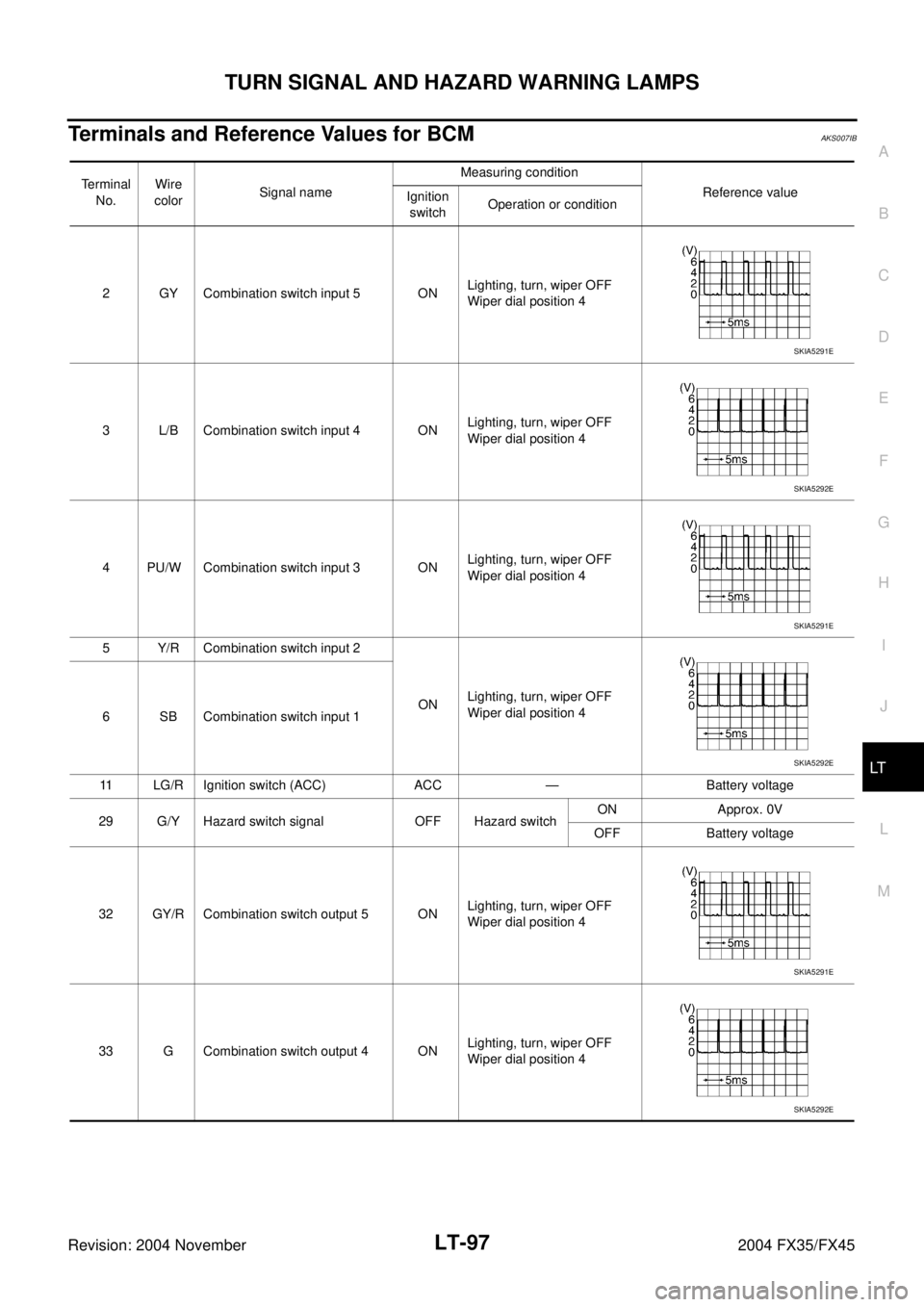
Terminals and Reference Values for BCMAKS007IB
Terminal
No.Wire
colorSignal nameMeasuring condition
Reference value
Ignition
switchOperation or condition
2 GY Combination switch input 5 ONLighting, turn, wiper OFF
Wiper dial position 4
3 L/B Combination switch input 4 ONLighting, turn, wiper OFF
Wiper dial position 4
4 PU/W Combination switch input 3 ONLighting, turn, wiper OFF
Wiper dial position 4
5 Y/R Combination switch input 2
ONLighting, turn, wiper OFF
Wiper dial position 4
6 SB Combination switch input 1
11 LG/R Ignition switch (ACC) ACC — Battery voltage
29 G/Y Hazard switch signal OFF Hazard switchON Approx. 0V
OFF Battery voltage
32 GY/R Combination switch output 5 ONLighting, turn, wiper OFF
Wiper dial position 4
33 G Combination switch output 4 ONLighting, turn, wiper OFF
Wiper dial position 4
SKIA5291E
SKIA5292E
SKIA5291E
SKIA5292E
SKIA5291E
SKIA5292E
Page 3653 of 4449
LT-98
TURN SIGNAL AND HAZARD WARNING LAMPS
Revision: 2004 November 2004 FX35/FX45
How to Proceed With Trouble DiagnosisAKS007D2
1. Confirm the symptom or customer complaint.
2. Understand operation description and function description. Refer to LT- 8 9 , "
System Description" .
3. Perform.preliminary check. Refer to LT- 9 9 , "
Preliminary Check" .
4. Check symptom and repair or replace the cause of malfunction.
5. Do turn signal and hazard warning lamps operate normally? If YES: GO TO 6. If NO: GO TO 4.
6. INSPECTION END
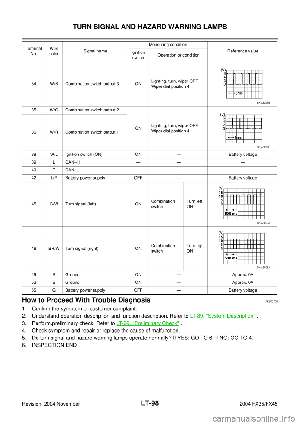
34 W/B Combination switch output 3 ONLighting, turn, wiper OFF
Wiper dial position 4
35 W/G Combination switch output 2
ONLighting, turn, wiper OFF
Wiper dial position 4
36 W/R Combination switch output 1
38 W/L Ignition switch (ON) ON — Battery voltage
39 L CAN−H—— —
40 R CAN−L—— —
42 L/R Battery power supply OFF — Battery voltage
45 G/W Turn signal (left) ONCombination
switchTurn le ft
ON
46 BR/W Turn signal (right) ONCombination
switchTurn right
ON
49 B Ground ON — Approx. 0V
52 B Ground ON — Approx. 0V
55 G Battery power supply OFF — Battery voltage Terminal
No.Wire
colorSignal nameMeasuring condition
Reference value
Ignition
switchOperation or condition
SKIA5291E
SKIA5292E
SKIA3009J
SKIA3009J
Page 3654 of 4449
TURN SIGNAL AND HAZARD WARNING LAMPS
LT-99
C
D
E
F
G
H
I
J
L
MA
B
LT
Revision: 2004 November 2004 FX35/FX45
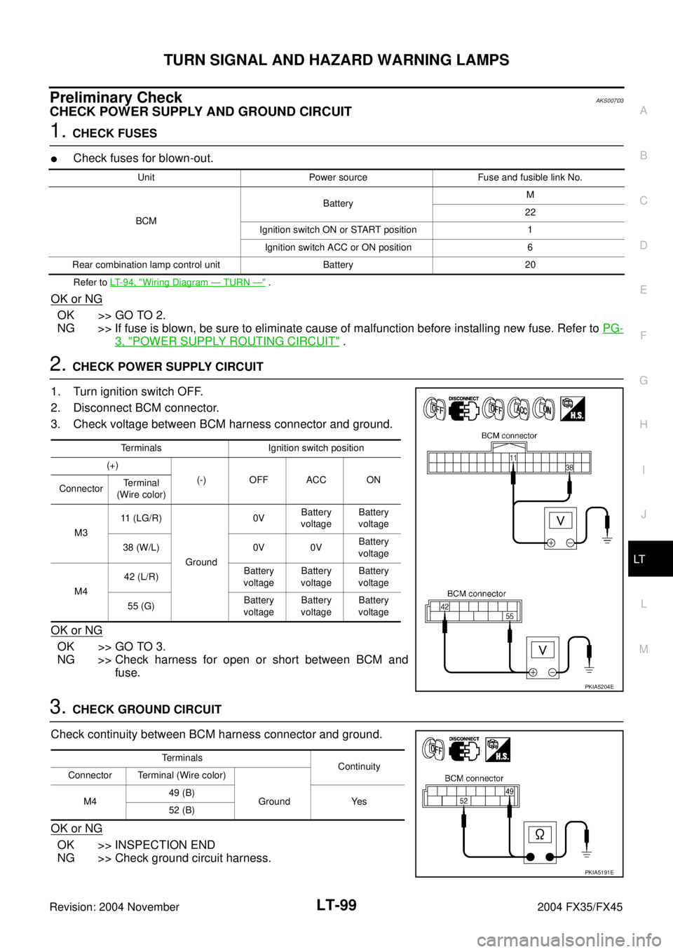
Preliminary CheckAKS007D3
CHECK POWER SUPPLY AND GROUND CIRCUIT
1. CHECK FUSES
�Check fuses for blown-out.
Refer to LT-94, "Wiring Diagram — TURN —" .
OK or NG
OK >> GO TO 2.
NG >> If fuse is blown, be sure to eliminate cause of malfunction before installing new fuse. Refer to PG-
3, "POWER SUPPLY ROUTING CIRCUIT" .
2. CHECK POWER SUPPLY CIRCUIT
1. Turn ignition switch OFF.
2. Disconnect BCM connector.
3. Check voltage between BCM harness connector and ground.
OK or NG
OK >> GO TO 3.
NG >> Check harness for open or short between BCM and
fuse.
3. CHECK GROUND CIRCUIT
Check continuity between BCM harness connector and ground.
OK or NG
OK >> INSPECTION END
NG >> Check ground circuit harness.
Unit Power source Fuse and fusible link No.
BCMBatteryM
22
Ignition switch ON or START position 1
Ignition switch ACC or ON position 6
Rear combination lamp control unit Battery 20
Terminals Ignition switch position
(+)
(-) OFF ACC ON
ConnectorTerminal
(Wire color)
M311 (LG/R)
Ground0VBattery
voltageBattery
voltage
38 (W/L) 0V 0VBattery
voltage
M442 (L/R)Battery
voltageBattery
voltageBattery
voltage
55 (G)Battery
voltageBattery
voltageBattery
voltage
PKIA5204E
Terminals
Continuity
Connector Terminal (Wire color)
M449 (B)
Ground Yes
52 (B)
PKIA5191E
Page 3659 of 4449
LT-104
TURN SIGNAL AND HAZARD WARNING LAMPS
Revision: 2004 November 2004 FX35/FX45
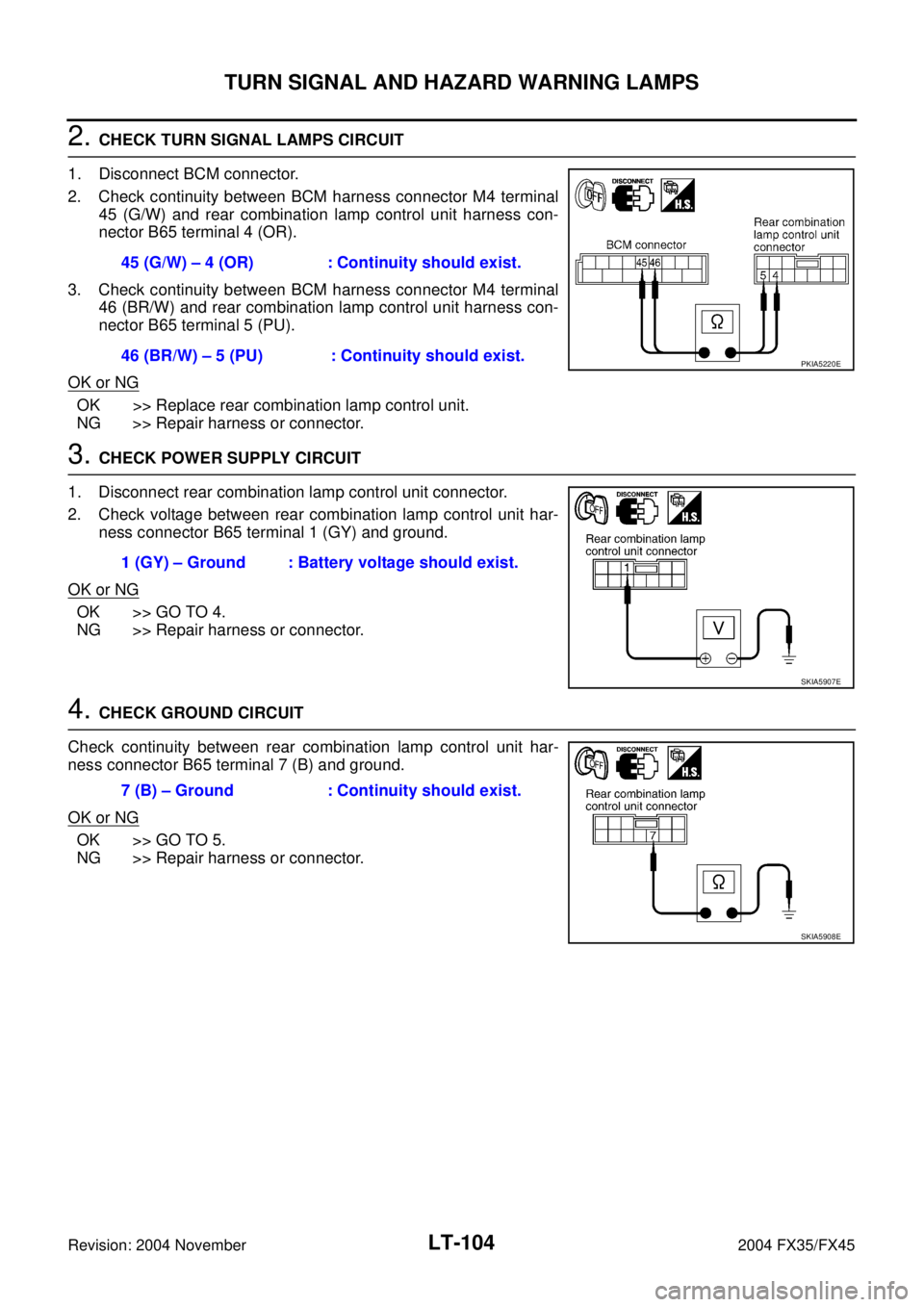
2. CHECK TURN SIGNAL LAMPS CIRCUIT
1. Disconnect BCM connector.
2. Check continuity between BCM harness connector M4 terminal
45 (G/W) and rear combination lamp control unit harness con-
nector B65 terminal 4 (OR).
3. Check continuity between BCM harness connector M4 terminal
46 (BR/W) and rear combination lamp control unit harness con-
nector B65 terminal 5 (PU).
OK or NG
OK >> Replace rear combination lamp control unit.
NG >> Repair harness or connector.
3. CHECK POWER SUPPLY CIRCUIT
1. Disconnect rear combination lamp control unit connector.
2. Check voltage between rear combination lamp control unit har-
ness connector B65 terminal 1 (GY) and ground.
OK or NG
OK >> GO TO 4.
NG >> Repair harness or connector.
4. CHECK GROUND CIRCUIT
Check continuity between rear combination lamp control unit har-
ness connector B65 terminal 7 (B) and ground.
OK or NG
OK >> GO TO 5.
NG >> Repair harness or connector.45 (G/W) – 4 (OR) : Continuity should exist.
46 (BR/W) – 5 (PU) : Continuity should exist.
PKIA5220E
1 (GY) – Ground : Battery voltage should exist.
SKIA5907E
7 (B) – Ground : Continuity should exist.
SKIA5908E