Page 3819 of 4449

MA-32
CHASSIS AND BODY MAINTENANCE
Revision: 2004 November 2004 FX35/FX45
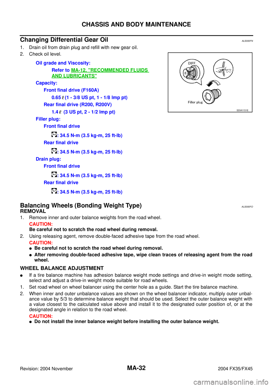
Changing Differential Gear OilALS000FN
1. Drain oil from drain plug and refill with new gear oil.
2. Check oil level.
Balancing Wheels (Bonding Weight Type)ALS000FO
REMOVAL
1. Remove inner and outer balance weights from the road wheel.
CAUTION:
Be careful not to scratch the road wheel during removal.
2. Using releasing agent, remove double-faced adhesive tape from the road wheel.
CAUTION:
�Be careful not to scratch the road wheel during removal.
�After removing double-faced adhesive tape, wipe clean traces of releasing agent from the road
wheel.
WHEEL BALANCE ADJUSTMENT
�If a tire balance machine has adhesion balance weight mode settings and drive-in weight mode setting,
select and adjust a drive-in weight mode suitable for road wheels.
1. Set road wheel on wheel balancer using the center hole as a guide. Start the tire balance machine.
2. When inner and outer unbalance values are shown on the wheel balancer indicator, multiply outer unbal-
ance value by 5/3 to determine balance weight that should be used. Select the outer balance weight with
a value closest to the calculated value above and install it to the designated outer position of, or at the
designated angle in relation to the road wheel.
CAUTION:
�Do not install the inner balance weight before installing the outer balance weight.Oil grade and Viscosity:
Refer to MA-12, "
RECOMMENDED FLUIDS
AND LUBRICANTS"
Capacity:
Front final drive (F160A)
0.65 (1 - 3/8 US pt, 1 - 1/8 lmp pt)
Rear final drive (R200, R200V)
1.4 (3 US pt, 2 - 1/2 lmp pt)
Filler plug:
Front final drive
: 34.5 N-m (3.5 kg-m, 25 ft-lb)
Rear final drive
: 34.5 N-m (3.5 kg-m, 25 ft-lb)
Drain plug:
Front final drive
: 34.5 N-m (3.5 kg-m, 25 ft-lb)
Rear final drive
: 34.5 N-m (3.5 kg-m, 25 ft-lb)
SDIA1151E
Page 3823 of 4449

MA-36
CHASSIS AND BODY MAINTENANCE
Revision: 2004 November 2004 FX35/FX45
Checking Power Steering Fluid and LinesALS000FV
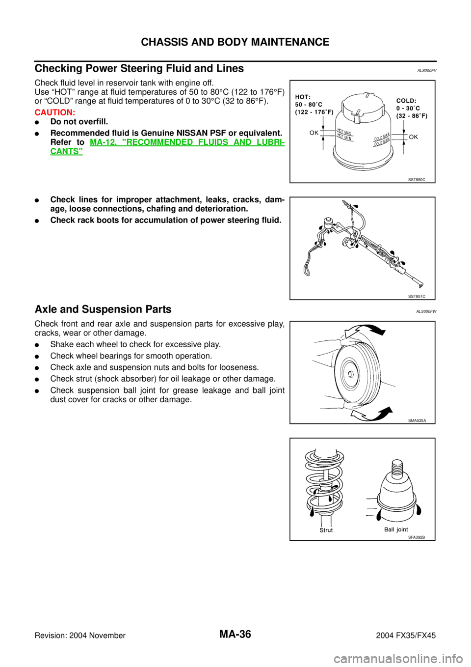
Check fluid level in reservoir tank with engine off.
Use “HOT” range at fluid temperatures of 50 to 80°C (122 to 176°F)
or “COLD” range at fluid temperatures of 0 to 30°C (32 to 86°F).
CAUTION:
�Do not overfill.
�Recommended fluid is Genuine NISSAN PSF or equivalent.
Refer to MA-12, "
RECOMMENDED FLUIDS AND LUBRI-
CANTS"
�Check lines for improper attachment, leaks, cracks, dam-
age, loose connections, chafing and deterioration.
�Check rack boots for accumulation of power steering fluid.
Axle and Suspension PartsALS000FW
Check front and rear axle and suspension parts for excessive play,
cracks, wear or other damage.
�Shake each wheel to check for excessive play.
�Check wheel bearings for smooth operation.
�Check axle and suspension nuts and bolts for looseness.
�Check strut (shock absorber) for oil leakage or other damage.
�Check suspension ball joint for grease leakage and ball joint
dust cover for cracks or other damage.
SST850C
SST851C
SMA525A
SFA392B
Page 3941 of 4449

PS-8
POWER STEERING FLUID
Revision: 2004 November 2004 FX35/FX45
POWER STEERING FLUIDPFP:KLF20
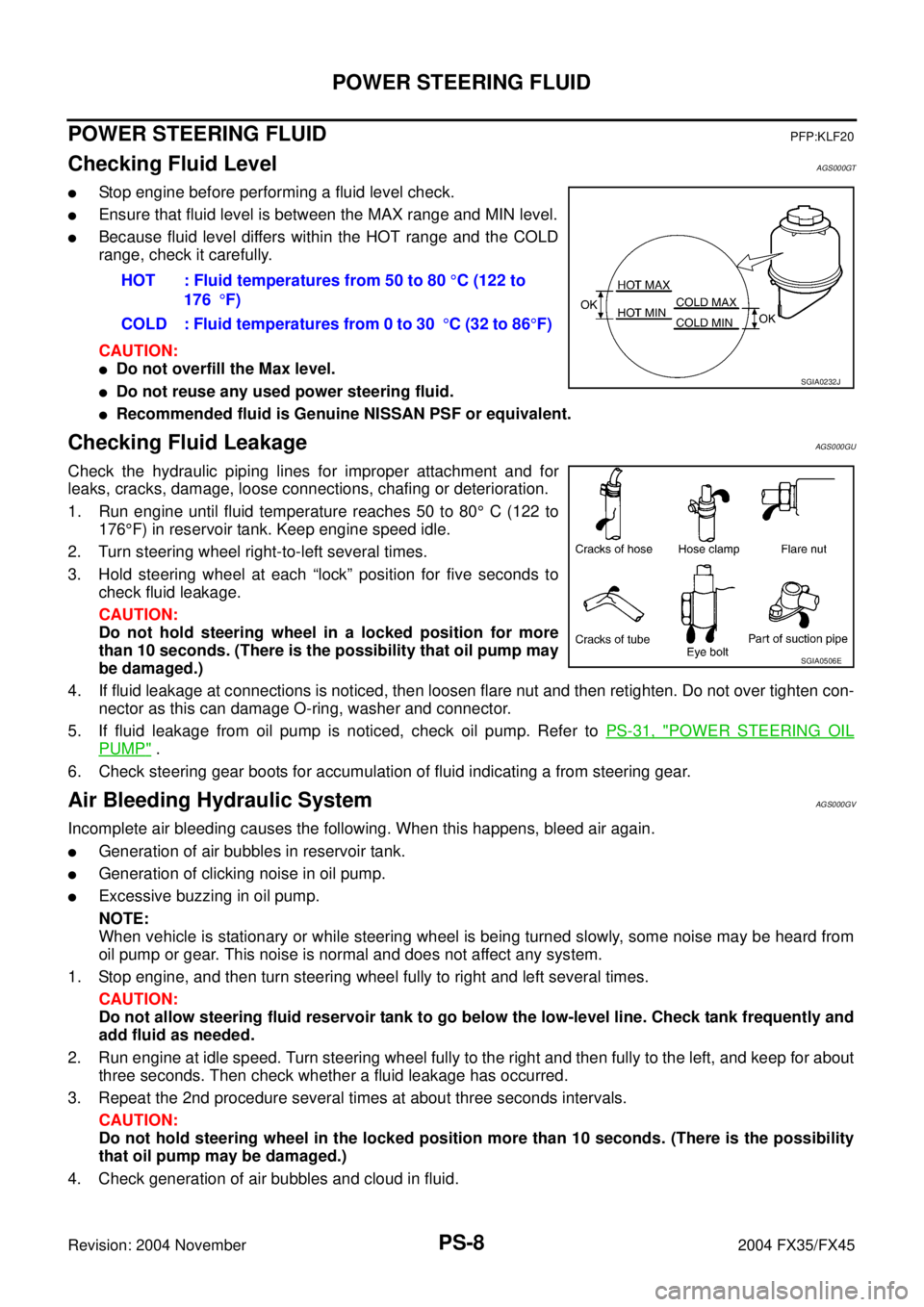
Checking Fluid LevelAGS000GT
�Stop engine before performing a fluid level check.
�Ensure that fluid level is between the MAX range and MIN level.
�Because fluid level differs within the HOT range and the COLD
range, check it carefully.
CAUTION:
�Do not overfill the Max level.
�Do not reuse any used power steering fluid.
�Recommended fluid is Genuine NISSAN PSF or equivalent.
Checking Fluid LeakageAGS000GU
Check the hydraulic piping lines for improper attachment and for
leaks, cracks, damage, loose connections, chafing or deterioration.
1. Run engine until fluid temperature reaches 50 to 80° C (122 to
176°F) in reservoir tank. Keep engine speed idle.
2. Turn steering wheel right-to-left several times.
3. Hold steering wheel at each “lock” position for five seconds to
check fluid leakage.
CAUTION:
Do not hold steering wheel in a locked position for more
than 10 seconds. (There is the possibility that oil pump may
be damaged.)
4. If fluid leakage at connections is noticed, then loosen flare nut and then retighten. Do not over tighten con-
nector as this can damage O-ring, washer and connector.
5. If fluid leakage from oil pump is noticed, check oil pump. Refer to PS-31, "
POWER STEERING OIL
PUMP" .
6. Check steering gear boots for accumulation of fluid indicating a from steering gear.
Air Bleeding Hydraulic SystemAGS000GV
Incomplete air bleeding causes the following. When this happens, bleed air again.
�Generation of air bubbles in reservoir tank.
�Generation of clicking noise in oil pump.
�Excessive buzzing in oil pump.
NOTE:
When vehicle is stationary or while steering wheel is being turned slowly, some noise may be heard from
oil pump or gear. This noise is normal and does not affect any system.
1. Stop engine, and then turn steering wheel fully to right and left several times.
CAUTION:
Do not allow steering fluid reservoir tank to go below the low-level line. Check tank frequently and
add fluid as needed.
2. Run engine at idle speed. Turn steering wheel fully to the right and then fully to the left, and keep for about
three seconds. Then check whether a fluid leakage has occurred.
3. Repeat the 2nd procedure several times at about three seconds intervals.
CAUTION:
Do not hold steering wheel in the locked position more than 10 seconds. (There is the possibility
that oil pump may be damaged.)
4. Check generation of air bubbles and cloud in fluid.HOT : Fluid temperatures from 50 to 80 °C (122 to
176°F)
COLD : Fluid temperatures from 0 to 30°C (32 to 86°F)
SGIA0232J
SGIA0506E
Page 4029 of 4449

RFD-2
PRECAUTIONS
Revision: 2004 November 2004 FX35/FX45
PRECAUTIONSPFP:00001
PrecautionsADS000K2
CAUTION:
�Before starting diagnosis of the vehicle, understand symptoms well. Perform correct and system-
atic operations.
�Check for the correct installation status prior removal or disassembly. When matching marks are
required, be sure they do not interfere with the function of the parts they are applied to.
�Carry out an overhaul in a clean work place, Using a dust proof room is recommended.
�Before disassembly, using steam or white gasoline, completely remove sand and mud from the
exterior the unit, preventing them from entering into the unit during disassembly or assembly.
�Check appearance of the disassembled parts for damage, deformation, and abnormal wear. If a
malfunction is detected, replace it with a new one.
�Normally replace lock pins, oil seals, and bearings with new ones every times they are removed.
�In principle, tighten bolts or nuts gradually in several steps working diagonally from inside to out-
side. If tightening sequence is specified, observe it.
�Clean and flush the parts sufficiently and blow them dry.
�Be careful not to damage the sliding surfaces and mating surface.
�When applying sealant, remove the old sealant from the mounting surface; then remove any mois-
ture, oil, and foreign materials from the application and mounting surfaces.
�Always use shop paper for cleaning the inside of components.
�Avoid using cotton gloves or a shop cloth to prevent entering of lint.
�During assembly, observe the specified tightening torque, and new differential gear oil, Vaseline,
or multi-purpose grease, as specified for each vehicle, when necessary.