Page 3857 of 4449

PG-22
IPDM E/R (INTELLIGENT POWER DISTRIBUTION MODULE ENGINE ROOM)
Revision: 2004 November 2004 FX35/FX45
DATA MONITOR
Operation Procedure
1. Touch “DATA MONITOR” on “SELECT MONITOR ITEM ” screen.
2. Touch “ALL SIGNALS”, “MAIN SIGNALS” or “SELECTION FROM MENU” on the “DATA MONITOR”
screen.
3. Touch “START”.
4. Touch the required monitoring item on “SELECTION FROM MENU”. In “ALL SIGNALS”, all items are
monitored. In “MAIN SIGNALS”, predetermined items are monitored.
5. Touch “RECORD” while monitoring to record the status of the item being monitored. To stop recording,
touch “STOP”.
All Signals, Main Signals, Selection From Menu
NOTE:
�Perform monitoring of IPDM E/R data with the ignition switch ON. When the ignition switch is at ACC, the
display may not be correct.
�The vehicle without the Intelligent Key system displays only ON without change.
�The cornering lamp items are displayed, but they cannot be monitored.
ACTIVE TEST
Operation Procedure
1. Touch “ACTIVE TEST” on “SELECT DIAG MODE” screen.
ALL SIGNALS All items will be monitored.
MAIN SIGNALS Monitor the predetermined item.
SELECTION FROM MENU Select any item for monitoring.
Item nameCONSULT-II screen
displayDisplay or unitMonitor item selection
Description
ALL
SIGNALSMAIN
SIGNALSSELEC-
TION
FROM
MENU
Motor fan request MOTOR FAN REQ 1/2/3/4×××Signal status input from ECM
Compressor request AC COMP REQ ON/OFF×××Signal status input from ECM
Tail & clear request TAIL&CLR REQ ON/OFF×××Signal status input from BCM
H/L LO request HL LO REQ ON/OFF×××Signal status input from BCM
H/L HI request HL HI REQ ON/OFF×××Signal status input from BCM
FR fog request FR FOG REQ ON/OFF×××Signal status input from BCM
FR wiper request FR WIP REQ STOP/1LO/LO/HI×××Signal status input from BCM
Wiper auto stop WIP AUTO STOP ACT P/STOP P×××Output status of IPDM E/R
Wiper protection WIP PROT OFF/LS/HS/Block×××Control status of IPDM E/R
Starter request ST RLY REQ ON/OFF××
Status of input signal
NOTE
Ignition relay status IGN RLY ON/OFF×××Ignition relay status monitored
with IPDM E/R
Rear window defog-
ger requestRR DEF REQ ON/OFF×××Signal status input from BCM
Oil pressure switch OIL P SW OPEN/CLOSE××Signal status input in IPDM E/R
Hood switch HOOD SW ON/OFF××Input signal status
Theft warning horn
requestTHFT HRN REQ ON/OFF××Signal status input from BCM
Horn chirp HORN CHIRP ON/OFF××Output status of IPDM E/R
Cornering lamp
request
NOTECRNRNG LMP REQ OFF/LEFT/RIGHT××Signal status input from BCM
Page 3957 of 4449

PS-24
POWER STEERING GEAR AND LINKAGE
Revision: 2004 November 2004 FX35/FX45
CAUTION:
When removing boots, be careful not to damage inner socket and gear housing assembly. If they
are damaged, change them to avoid oil leaks.
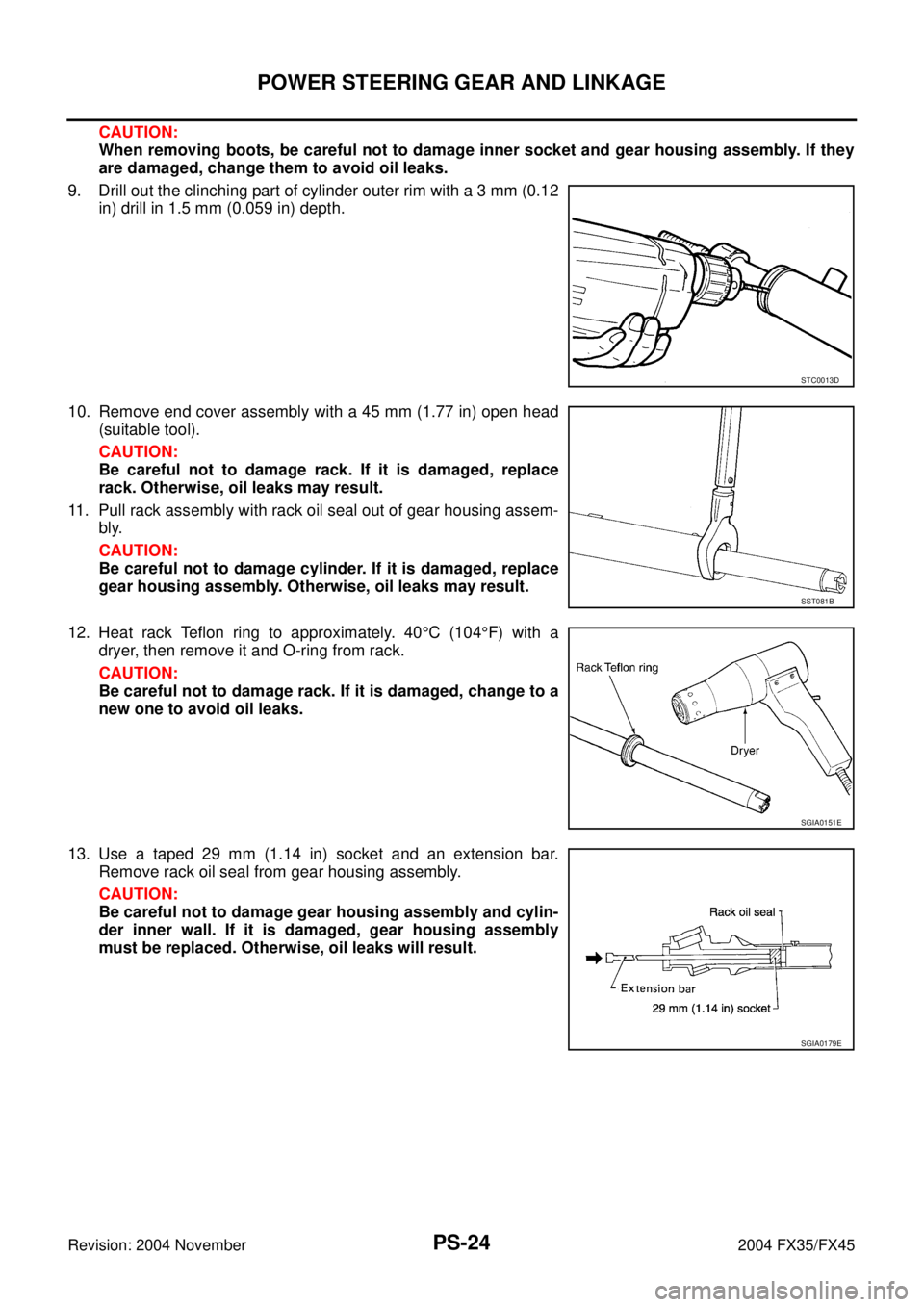
9. Drill out the clinching part of cylinder outer rim with a 3 mm (0.12
in) drill in 1.5 mm (0.059 in) depth.
10. Remove end cover assembly with a 45 mm (1.77 in) open head
(suitable tool).
CAUTION:
Be careful not to damage rack. If it is damaged, replace
rack. Otherwise, oil leaks may result.
11. Pull rack assembly with rack oil seal out of gear housing assem-
bly.
CAUTION:
Be careful not to damage cylinder. If it is damaged, replace
gear housing assembly. Otherwise, oil leaks may result.
12. Heat rack Teflon ring to approximately. 40°C (104°F) with a
dryer, then remove it and O-ring from rack.
CAUTION:
Be careful not to damage rack. If it is damaged, change to a
new one to avoid oil leaks.
13. Use a taped 29 mm (1.14 in) socket and an extension bar.
Remove rack oil seal from gear housing assembly.
CAUTION:
Be careful not to damage gear housing assembly and cylin-
der inner wall. If it is damaged, gear housing assembly
must be replaced. Otherwise, oil leaks will result.
STC0013D
SST081B
SGIA0151E
SGIA0179E
Page 4037 of 4449

RFD-10
SIDE OIL SEAL
Revision: 2004 November 2004 FX35/FX45
INSTALLATION
1. Apply multi-purpose grease to sealing lips of side oil seal.
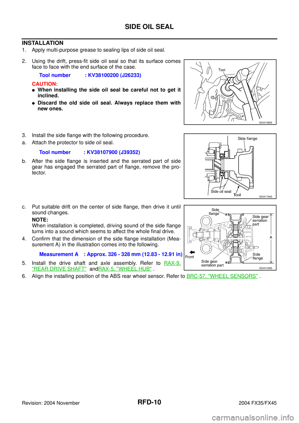
2. Using the drift, press-fit side oil seal so that its surface comes
face to face with the end surface of the case.
CAUTION:
�When installing the side oil seal be careful not to get it
inclined.
�Discard the old side oil seal. Always replace them with
new ones.
3. Install the side flange with the following procedure.
a. Attach the protector to side oil seal.
b. After the side flange is inserted and the serrated part of side
gear has engaged the serrated part of flange, remove the pro-
tector.
c. Put suitable drift on the center of side flange, then drive it until
sound changes.
NOTE:
When installation is completed, driving sound of the side flange
turns into a sound which seems to affect the whole final drive.
4. Confirm that the dimension of the side flange installation (Mea-
surement A) in the illustration comes into the following.
5. Install the drive shaft and axle assembly. Refer to RAX-9,
"REAR DRIVE SHAFT" andRAX-5, "WHEEL HUB" .
6. Align the installing position of the ABS rear wheel sensor. Refer to BRC-57, "
WHEEL SENSORS" . Tool number : KV38100200 (J26233)
SDIA1585E
Tool number : KV38107900 (J39352)
SDIA1794E
Measurement A : Approx. 326 - 328 mm (12.83 - 12.91 in)
SDIA1039E