Page 3654 of 4449

TURN SIGNAL AND HAZARD WARNING LAMPS
LT-99
C
D
E
F
G
H
I
J
L
MA
B
LT
Revision: 2004 November 2004 FX35/FX45
Preliminary CheckAKS007D3
CHECK POWER SUPPLY AND GROUND CIRCUIT
1. CHECK FUSES
�Check fuses for blown-out.
Refer to LT-94, "Wiring Diagram — TURN —" .
OK or NG
OK >> GO TO 2.
NG >> If fuse is blown, be sure to eliminate cause of malfunction before installing new fuse. Refer to PG-
3, "POWER SUPPLY ROUTING CIRCUIT" .
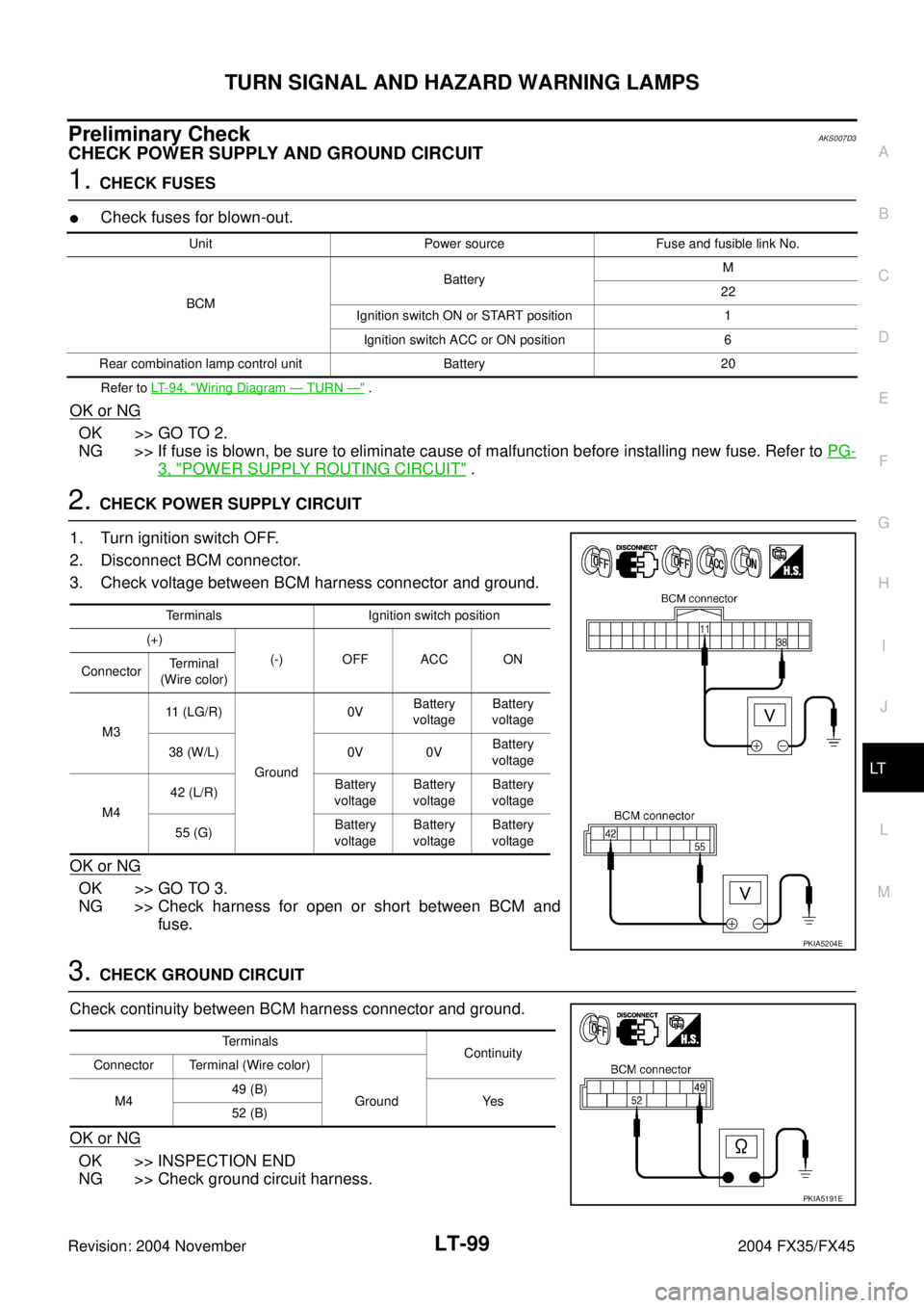
2. CHECK POWER SUPPLY CIRCUIT
1. Turn ignition switch OFF.
2. Disconnect BCM connector.
3. Check voltage between BCM harness connector and ground.
OK or NG
OK >> GO TO 3.
NG >> Check harness for open or short between BCM and
fuse.
3. CHECK GROUND CIRCUIT
Check continuity between BCM harness connector and ground.
OK or NG
OK >> INSPECTION END
NG >> Check ground circuit harness.
Unit Power source Fuse and fusible link No.
BCMBatteryM
22
Ignition switch ON or START position 1
Ignition switch ACC or ON position 6
Rear combination lamp control unit Battery 20
Terminals Ignition switch position
(+)
(-) OFF ACC ON
ConnectorTerminal
(Wire color)
M311 (LG/R)
Ground0VBattery
voltageBattery
voltage
38 (W/L) 0V 0VBattery
voltage
M442 (L/R)Battery
voltageBattery
voltageBattery
voltage
55 (G)Battery
voltageBattery
voltageBattery
voltage
PKIA5204E
Terminals
Continuity
Connector Terminal (Wire color)
M449 (B)
Ground Yes
52 (B)
PKIA5191E
Page 3665 of 4449
LT-110
COMBINATION SWITCH
Revision: 2004 November 2004 FX35/FX45
COMBINATION SWITCHPFP:25567
Wiring Diagram — COMBSW —AKS007G4
TKWM0814E
Page 3673 of 4449
LT-118
STOP LAMP
Revision: 2004 November 2004 FX35/FX45
Wiring Diagram — STOP/L —AKS007DL
TKWH0226E
Page 3680 of 4449
BACK-UP LAMP
LT-125
C
D
E
F
G
H
I
J
L
MA
B
LT
Revision: 2004 November 2004 FX35/FX45
BACK-UP LAMPPFP:26550
Wiring Diagram — BACK/L —AKS007DQ
TKWM1277E
Page 3684 of 4449

PARKING, LICENSE PLATE AND TAIL LAMPS
LT-129
C
D
E
F
G
H
I
J
L
MA
B
LT
Revision: 2004 November 2004 FX35/FX45
With power and ground supplied, the parking, license plate, side marker and tail lamps illuminate.
COMBINATION SWITCH READING FUNCTION
Refer to BCS-3, "COMBINATION SWITCH READING FUNCTION" .
EXTERIOR LAMP BATTERY SAVER CONTROL
When the combination switch (lighting switch) is in the 1ST (or 2ND) position, and the ignition switch is turned
from ON or ACC to OFF, the battery saver control feature is activated.
Under this condition, the parking, license, side marker and tail lamps remain illuminated for 5 minutes, then the
parking, license plate, side marker and tail lamps are turned off.
Exterior lamp battery saver control mode can be changed by the function setting of CONSULT-II.
CAN Communication System DescriptionAKS007DU
CAN (Controller Area Network) is a serial communication line for real time application. It is an on-vehicle mul-
tiplex communication line with high data communication speed and excellent error detection ability. Many elec-
tronic control units are equipped onto a vehicle, and each control unit shares information and links with other
control units during operation (not independent). In CAN communication, control units are connected with 2
communication lines (CAN H line, CAN L line) allowing a high rate of information transmission with less wiring.
Each control unit transmits/receives data but selectively reads required data only.
CAN Communication UnitAKS0080X
Refer to LAN-6, "CAN Communication Unit" .
Page 3686 of 4449
PARKING, LICENSE PLATE AND TAIL LAMPS
LT-131
C
D
E
F
G
H
I
J
L
MA
B
LT
Revision: 2004 November 2004 FX35/FX45
Wiring Diagram — TAIL/L —AKS007DX
TKWM0821E
Page 3693 of 4449

LT-138
PARKING, LICENSE PLATE AND TAIL LAMPS
Revision: 2004 November 2004 FX35/FX45
Refer to LT- 1 3 1 , "Wiring Diagram — TAIL/L —" .
OK or NG
OK >> GO TO 2.
NG >> If fuse is blown, be sure to eliminate cause of malfunction before installing new fuse. Refer to PG-
3, "POWER SUPPLY ROUTING CIRCUIT" .
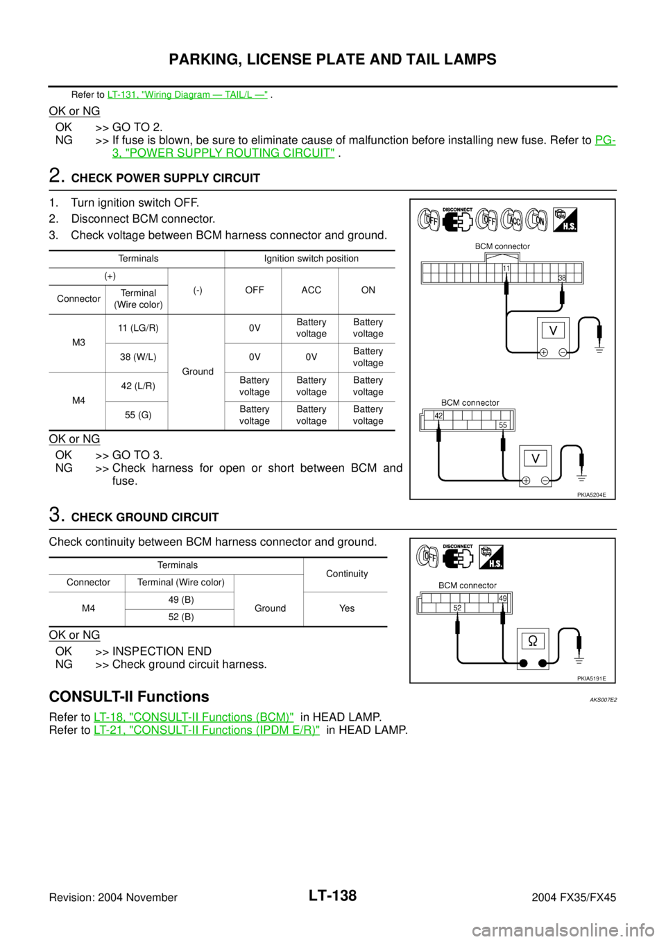
2. CHECK POWER SUPPLY CIRCUIT
1. Turn ignition switch OFF.
2. Disconnect BCM connector.
3. Check voltage between BCM harness connector and ground.
OK or NG
OK >> GO TO 3.
NG >> Check harness for open or short between BCM and
fuse.
3. CHECK GROUND CIRCUIT
Check continuity between BCM harness connector and ground.
OK or NG
OK >> INSPECTION END
NG >> Check ground circuit harness.
CONSULT-II FunctionsAKS007E2
Refer to LT- 1 8 , "CONSULT-II Functions (BCM)" in HEAD LAMP.
Refer to LT- 2 1 , "
CONSULT-II Functions (IPDM E/R)" in HEAD LAMP.
Terminals Ignition switch position
(+)
(-) OFF ACC ON
ConnectorTerminal
(Wire color)
M311 (LG/R)
Ground0VBattery
voltageBattery
voltage
38 (W/L) 0V 0VBattery
voltage
M442 (L/R)Battery
voltageBattery
voltageBattery
voltage
55 (G)Battery
voltageBattery
voltageBattery
voltage
PKIA5204E
Terminals
Continuity
Connector Terminal (Wire color)
M449 (B)
Ground Yes
52 (B)
PKIA5191E
Page 3719 of 4449
LT-164
INTERIOR ROOM LAMP
Revision: 2004 November 2004 FX35/FX45
Wiring Diagram — ROOM/L —AKS007FA
TKWM0824E