Page 3245 of 4449
GW-86
REAR WINDOW DEFOGGER
Revision: 2004 November 2004 FX35/FX45
REAR WINDOW DEFOGGERPFP:25350
Component Parts and Harness Connector LocationAIS004QY
System DescriptionAIS004QZ
The rear window defogger system is controlled by BCM (Body Control Module) and IPDM E/R (Intelligent
Power Distribution Module Engine Room).
The rear window defogger operates only for approximately 15 minutes.
Power is at all times supplied
�through 20A fuse [No. 75, and 80, located in the IPDM E/R]
�to rear window defogger relay terminals 3 and 6.
�through 10A fuse [No.12, located in the fuse block]
�to rear window defogger relay terminal 1.
�through 15A fuse [No. 32, located in the fuse block (J/B)]
PIIA6408E
Page 3246 of 4449

REAR WINDOW DEFOGGER
GW-87
C
D
E
F
G
H
J
K
L
MA
B
GW
Revision: 2004 November 2004 FX35/FX45
�to A/C and AV switch terminal 1.
�through 50A fusible link (letter M , located in the fuse and fusible link box)
�to BCM terminal 55.
�through 15A fuse [No.22, located in the fuse block (J/B)]
�to BCM terminal 42.
With the ignition switch turned to ON or START position,
Power is supplied
�through 15A fuse [No.1, located in the fuse block (J/B)]
�to BCM terminal 38.
Ground is supplied
�to BCM terminal 49 and 52
�through body grounds M35, M45 and M85.
�to A/C and AV switch terminal 5
�through body grounds M35, M45 and M85.
�to IPDM E/R terminals 38 and 60
�through body grounds E21, E50 and E51.
When rear window defogger switch in A/C and AV switch is turned to ON,
Ground is supplied
�to BCM terminal 9
�through A/C and AV switch terminal 16
�through A/C and AV switch terminal 5
�through body grounds M35, M45 and M85.
Then rear window defogger switch is illuminated.
Then BCM recognizes that rear window defogger switch is turned to ON.
Then it sends rear window defogger switch signals to IPDM E/R, display control unit (with navigation system)
or display unit (without navigation system) via DATA LINE (CAN H, CAN L).
When display control unit (with navigation system) or display unit (without navigation system) receives rear
window defogger switch signals, and display on the screen.
When IPDM E/R receives rear window defogger switch signals,
Ground is supplied
�to rear window defogger relay terminal 2
�through IPDM E/R terminal 52
�through IPDM E/R terminals 38 and 60
�through body grounds E21, E50 and E51,
and then rear window defogger relay is energized.
When rear window defogger relay is turned ON,
Signals are transmitted,
�through rear window defogger relay terminals 5 and 7
�to rear window defogger terminal 1
�Rear window defogger terminal 2 is grounded through body grounds B15 and B45.
With power and ground supplied, rear window defogger filaments heat and defog the rear window.
When rear window defogger relay is turned to ON,
Power is supplied
�through rear window defogger relay terminal 7
�through fuse block (J/B) terminal 2C
�through 15A fuse [No. 8, located in the fuse block (J/B)]
�through fuse block (J/B) terminal 5B
�to door mirror defogger (driver side and passenger side) terminal 1.
Door mirror defogger (driver side and passenger side) terminal 2 is grounded through body grounds M35, M45
and M85.
With power and ground supplied, rear window defogger filaments heat and defog the rear window and door
mirror defogger filaments heat and defog the mirror.
Page 3256 of 4449

REAR WINDOW DEFOGGER
GW-97
C
D
E
F
G
H
J
K
L
MA
B
GW
Revision: 2004 November 2004 FX35/FX45
Trouble Diagnoses Symptom ChartAIS004R8
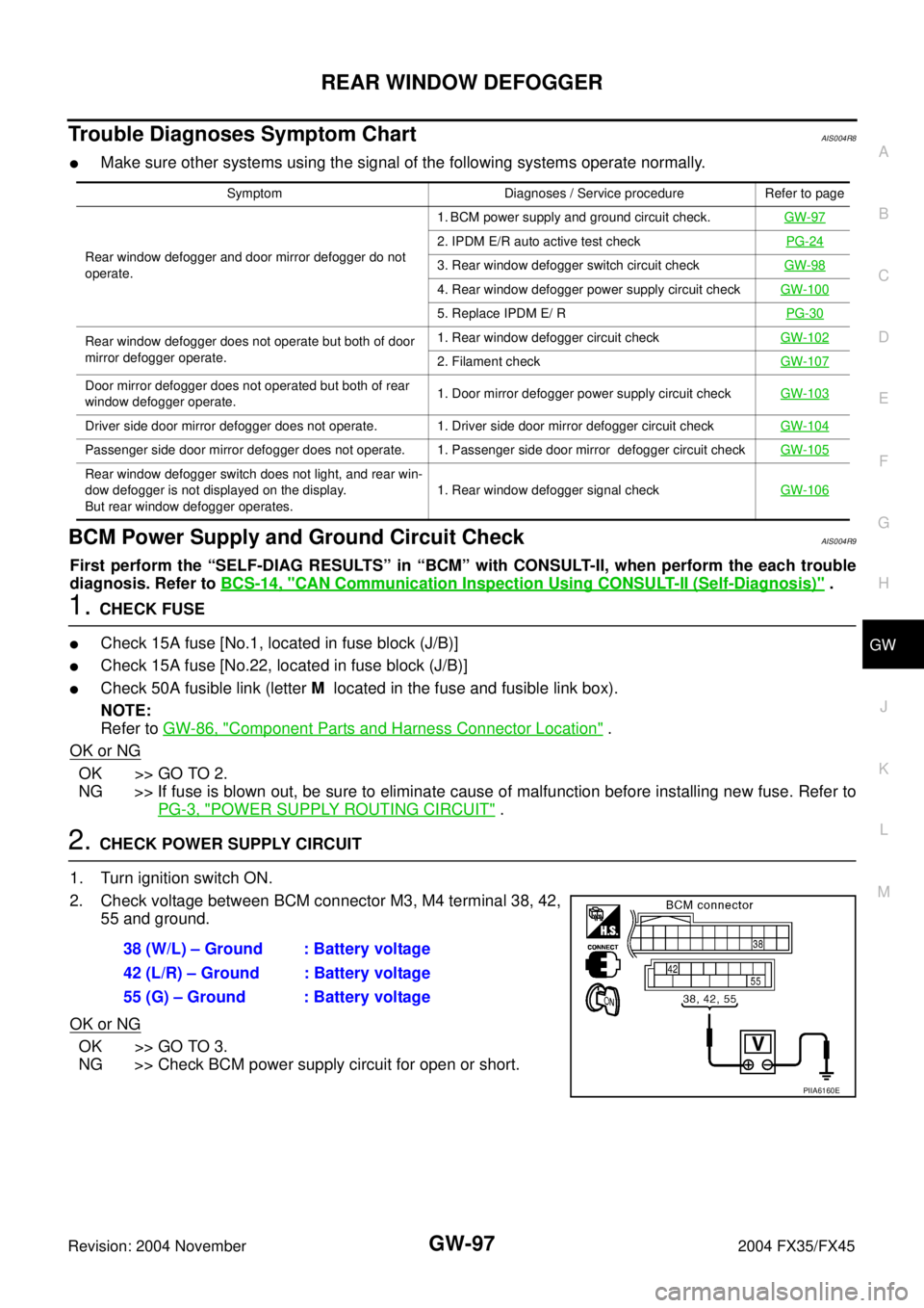
�Make sure other systems using the signal of the following systems operate normally.
BCM Power Supply and Ground Circuit CheckAIS004R9
First perform the “SELF-DIAG RESULTS” in “BCM” with CONSULT-II, when perform the each trouble
diagnosis. Refer to BCS-14, "
CAN Communication Inspection Using CONSULT-II (Self-Diagnosis)" .
1. CHECK FUSE
�Check 15A fuse [No.1, located in fuse block (J/B)]
�Check 15A fuse [No.22, located in fuse block (J/B)]
�Check 50A fusible link (letter M located in the fuse and fusible link box).
NOTE:
Refer to GW-86, "
Component Parts and Harness Connector Location" .
OK or NG
OK >> GO TO 2.
NG >> If fuse is blown out, be sure to eliminate cause of malfunction before installing new fuse. Refer to
PG-3, "
POWER SUPPLY ROUTING CIRCUIT" .
2. CHECK POWER SUPPLY CIRCUIT
1. Turn ignition switch ON.
2. Check voltage between BCM connector M3, M4 terminal 38, 42,
55 and ground.
OK or NG
OK >> GO TO 3.
NG >> Check BCM power supply circuit for open or short.
Symptom Diagnoses / Service procedure Refer to page
Rear window defogger and door mirror defogger do not
operate. 1. BCM power supply and ground circuit check.GW-97
2. IPDM E/R auto active test checkPG-24
3. Rear window defogger switch circuit checkGW-98
4. Rear window defogger power supply circuit checkGW-100
5. Replace IPDM E/ RPG-30
Rear window defogger does not operate but both of door
mirror defogger operate.1. Rear window defogger circuit checkGW-102
2. Filament checkGW-107
Door mirror defogger does not operated but both of rear
window defogger operate. 1. Door mirror defogger power supply circuit checkGW-103
Driver side door mirror defogger does not operate. 1. Driver side door mirror defogger circuit checkGW-104
Passenger side door mirror defogger does not operate. 1. Passenger side door mirror defogger circuit checkGW-105
Rear window defogger switch does not light, and rear win-
dow defogger is not displayed on the display.
But rear window defogger operates. 1. Rear window defogger signal checkGW-106
38 (W/L) – Ground : Battery voltage
42 (L/R) – Ground : Battery voltage
55 (G) – Ground : Battery voltage
PIIA6160E
Page 3259 of 4449
![INFINITI FX35 2004 Service Manual GW-100
REAR WINDOW DEFOGGER
Revision: 2004 November 2004 FX35/FX45
Rear Window Defogger Power Supply Circuit CheckAIS004RB
1. CHECK FUSE
�Check 10A fuse [No.12, located in fuse block (J/B)]
�Check 20 INFINITI FX35 2004 Service Manual GW-100
REAR WINDOW DEFOGGER
Revision: 2004 November 2004 FX35/FX45
Rear Window Defogger Power Supply Circuit CheckAIS004RB
1. CHECK FUSE
�Check 10A fuse [No.12, located in fuse block (J/B)]
�Check 20](/manual-img/42/57021/w960_57021-3258.png)
GW-100
REAR WINDOW DEFOGGER
Revision: 2004 November 2004 FX35/FX45
Rear Window Defogger Power Supply Circuit CheckAIS004RB
1. CHECK FUSE
�Check 10A fuse [No.12, located in fuse block (J/B)]
�Check 20A fuse (No.75, located in the IPDM E/R)
�Check 20A fuse (No.80, located in the IPDM E/R)
NOTE:
Refer to GW-86, "
Component Parts and Harness Connector Location" .
OK or NG
OK >> GO TO 2.
NG >> If fuse is blown out, be sure to eliminate cause of malfunction before installing new fuse, refer to
PG-3, "
POWER SUPPLY ROUTING CIRCUIT" .
2. CHECK POWER SUPPLY CIRCUIT
1. Turn ignition switch OFF.
2. Remove rear window defogger relay.
3. Turn ignition switch ON.
4. Check voltage between rear window defogger relay connector
and ground.
OK or NG
OK >> GO TO 3.
NG >> Repair or replace harness between fuse block (J/B) and
rear window defogger relay.
3. CHECK REAR WINDOW DEFOGGER RELAY
Check continuity between rear window defogger terminals 3 and 5, 6
and 7.
OK or NG
OK >> GO TO 4.
NG >> Replace rear window defogger relay.
ConnectorTerminals (Wire color)
Voltage (V)
(Approx.)
(+) (-)
E131 (OR)
Ground Battery voltage 3 (W)
6 (R)
PIIA4233E
Terminal Condition Continuity
3512V direct current supply
between terminals 1 and 2Ye s
No current supply No
6712V direct current supply
between terminals 1 and 2Ye s
No current supply No
SEC202B
Page 3262 of 4449

REAR WINDOW DEFOGGER
GW-103
C
D
E
F
G
H
J
K
L
MA
B
GW
Revision: 2004 November 2004 FX35/FX45
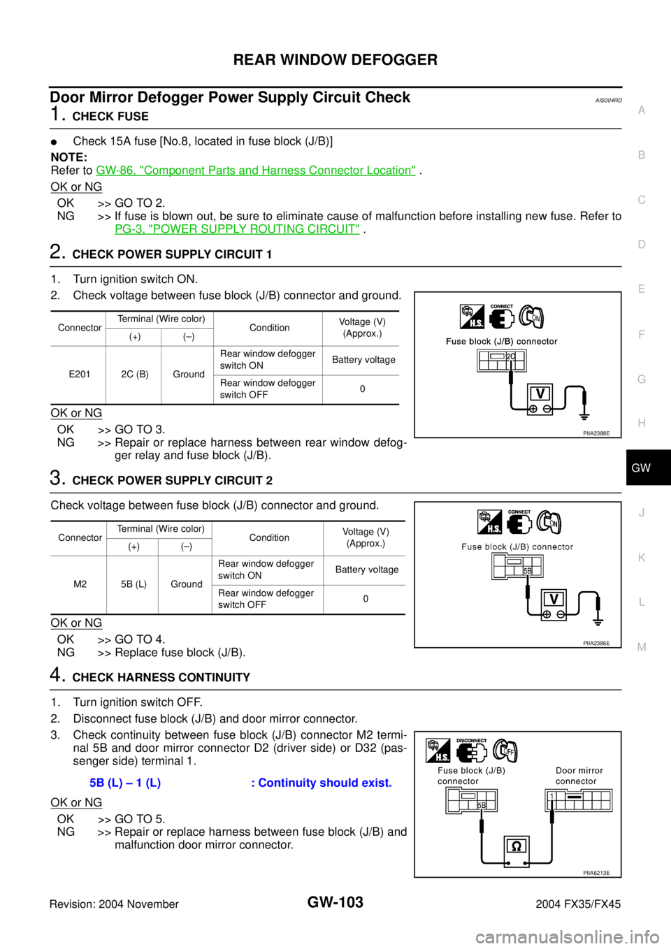
Door Mirror Defogger Power Supply Circuit CheckAIS004RD
1. CHECK FUSE
�Check 15A fuse [No.8, located in fuse block (J/B)]
NOTE:
Refer to GW-86, "
Component Parts and Harness Connector Location" .
OK or NG
OK >> GO TO 2.
NG >> If fuse is blown out, be sure to eliminate cause of malfunction before installing new fuse. Refer to
PG-3, "
POWER SUPPLY ROUTING CIRCUIT" .
2. CHECK POWER SUPPLY CIRCUIT 1
1. Turn ignition switch ON.
2. Check voltage between fuse block (J/B) connector and ground.
OK or NG
OK >> GO TO 3.
NG >> Repair or replace harness between rear window defog-
ger relay and fuse block (J/B).
3. CHECK POWER SUPPLY CIRCUIT 2
Check voltage between fuse block (J/B) connector and ground.
OK or NG
OK >> GO TO 4.
NG >> Replace fuse block (J/B).
4. CHECK HARNESS CONTINUITY
1. Turn ignition switch OFF.
2. Disconnect fuse block (J/B) and door mirror connector.
3. Check continuity between fuse block (J/B) connector M2 termi-
nal 5B and door mirror connector D2 (driver side) or D32 (pas-
senger side) terminal 1.
OK or NG
OK >> GO TO 5.
NG >> Repair or replace harness between fuse block (J/B) and
malfunction door mirror connector.
ConnectorTerminal (Wire color)
ConditionVoltage (V)
(Approx.)
(+) (–)
E201 2C (B) GroundRear window defogger
switch ON Battery voltage
Rear window defogger
switch OFF0
PIIA2388E
ConnectorTerminal (Wire color)
ConditionVoltage (V)
(Approx.)
(+) (–)
M2 5B (L) GroundRear window defogger
switch ON Battery voltage
Rear window defogger
switch OFF0
PIIA2386E
5B (L) – 1 (L) : Continuity should exist.
PIIA6213E
Page 3263 of 4449

GW-104
REAR WINDOW DEFOGGER
Revision: 2004 November 2004 FX35/FX45
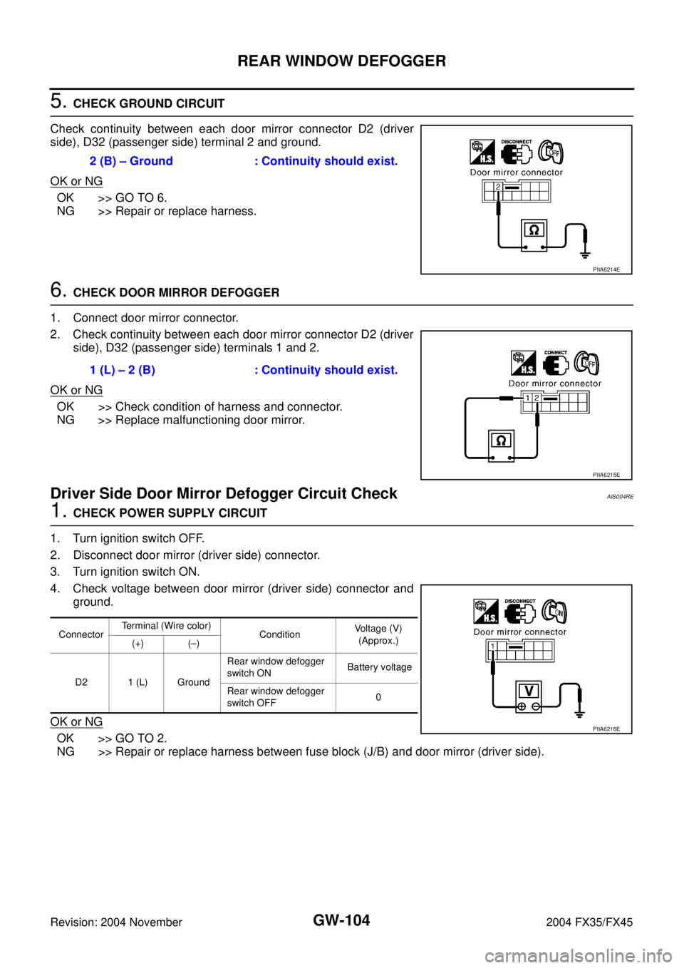
5. CHECK GROUND CIRCUIT
Check continuity between each door mirror connector D2 (driver
side), D32 (passenger side) terminal 2 and ground.
OK or NG
OK >> GO TO 6.
NG >> Repair or replace harness.
6. CHECK DOOR MIRROR DEFOGGER
1. Connect door mirror connector.
2. Check continuity between each door mirror connector D2 (driver
side), D32 (passenger side) terminals 1 and 2.
OK or NG
OK >> Check condition of harness and connector.
NG >> Replace malfunctioning door mirror.
Driver Side Door Mirror Defogger Circuit CheckAIS004RE
1. CHECK POWER SUPPLY CIRCUIT
1. Turn ignition switch OFF.
2. Disconnect door mirror (driver side) connector.
3. Turn ignition switch ON.
4. Check voltage between door mirror (driver side) connector and
ground.
OK or NG
OK >> GO TO 2.
NG >> Repair or replace harness between fuse block (J/B) and door mirror (driver side).2 (B) – Ground : Continuity should exist.
PIIA6214E
1 (L) – 2 (B) : Continuity should exist.
PIIA6215E
ConnectorTerminal (Wire color)
ConditionVoltage (V)
(Approx.)
(+) (–)
D2 1 (L) GroundRear window defogger
switch ON Battery voltage
Rear window defogger
switch OFF0
PIIA6216E
Page 3264 of 4449

REAR WINDOW DEFOGGER
GW-105
C
D
E
F
G
H
J
K
L
MA
B
GW
Revision: 2004 November 2004 FX35/FX45
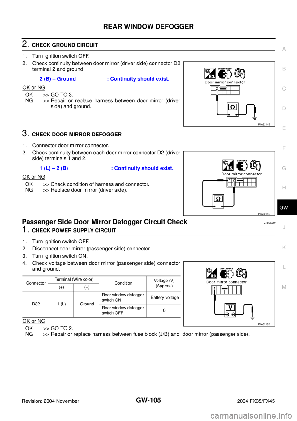
2. CHECK GROUND CIRCUIT
1. Turn ignition switch OFF.
2. Check continuity between door mirror (driver side) connector D2
terminal 2 and ground.
OK or NG
OK >> GO TO 3.
NG >> Repair or replace harness between door mirror (driver
side) and ground.
3. CHECK DOOR MIRROR DEFOGGER
1. Connector door mirror connector.
2. Check continuity between each door mirror connector D2 (driver
side) terminals 1 and 2.
OK or NG
OK >> Check condition of harness and connector.
NG >> Replace door mirror (driver side).
Passenger Side Door Mirror Defogger Circuit Check AIS004RF
1. CHECK POWER SUPPLY CIRCUIT
1. Turn ignition switch OFF.
2. Disconnect door mirror (passenger side) connector.
3. Turn ignition switch ON.
4. Check voltage between door mirror (passenger side) connector
and ground.
OK or NG
OK >> GO TO 2.
NG >> Repair or replace harness between fuse block (J/B) and door mirror (passenger side).2 (B) – Ground : Continuity should exist.
PIIA6214E
1 (L) – 2 (B) : Continuity should exist.
PIIA6215E
ConnectorTerminal (Wire color)
ConditionVoltage (V)
(Approx.)
(+) (–)
D32 1 (L) GroundRear window defogger
switch ON Battery voltage
Rear window defogger
switch OFF0
PIIA6216E
Page 3269 of 4449
GW-110
DOOR MIRROR
Revision: 2004 November 2004 FX35/FX45
Automatic Drive Positioner Interlocking Door Mirror AIS003L5
A trouble diagnosis of a automatic drive positioner interlocking door mirror is refer to SE-11, "AUTOMATIC
DRIVE POSITIONER" .