Page 3637 of 4449

LT-82
FRONT FOG LAMP
Revision: 2004 November 2004 FX35/FX45
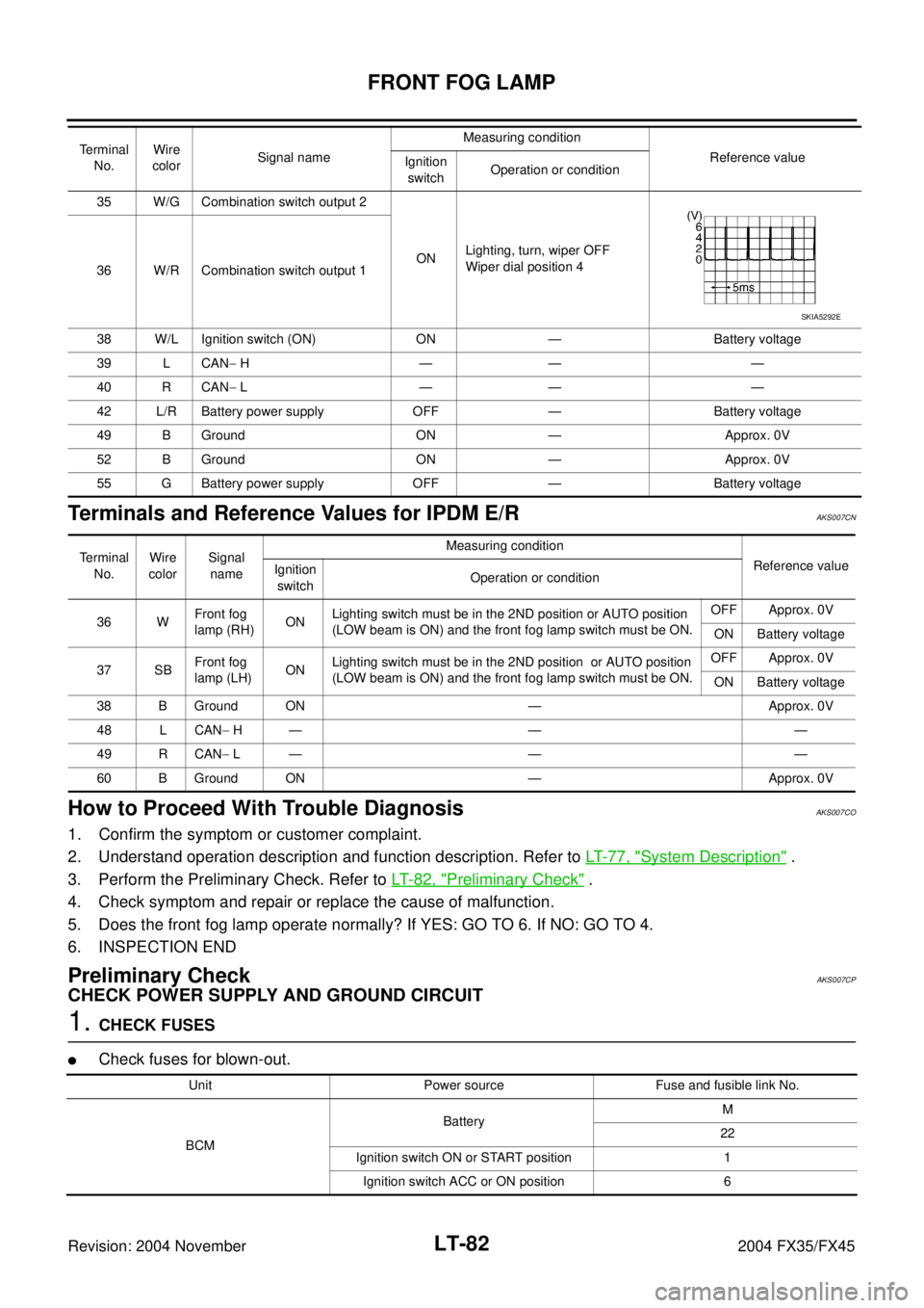
Terminals and Reference Values for IPDM E/RAKS007CN
How to Proceed With Trouble DiagnosisAKS007CO
1. Confirm the symptom or customer complaint.
2. Understand operation description and function description. Refer to LT- 7 7 , "
System Description" .
3. Perform the Preliminary Check. Refer to LT- 8 2 , "
Preliminary Check" .
4. Check symptom and repair or replace the cause of malfunction.
5. Does the front fog lamp operate normally? If YES: GO TO 6. If NO: GO TO 4.
6. INSPECTION END
Preliminary CheckAKS007CP
CHECK POWER SUPPLY AND GROUND CIRCUIT
1. CHECK FUSES
�Check fuses for blown-out.
35 W/G Combination switch output 2
ONLighting, turn, wiper OFF
Wiper dial position 4
36 W/R Combination switch output 1
38 W/L Ignition switch (ON) ON — Battery voltage
39 L CAN− H—— —
40 R CAN− L—— —
42 L/R Battery power supply OFF — Battery voltage
49 B Ground ON — Approx. 0V
52 B Ground ON — Approx. 0V
55 G Battery power supply OFF — Battery voltage Terminal
No.Wire
colorSignal nameMeasuring condition
Reference value
Ignition
switchOperation or condition
SKIA5292E
Terminal
No.Wire
colorSignal
nameMeasuring condition
Reference value
Ignition
switchOperation or condition
36 WFront fog
lamp (RH) ONLighting switch must be in the 2ND position or AUTO position
(LOW beam is ON) and the front fog lamp switch must be ON.OFF Approx. 0V
ON Battery voltage
37 SBFront fog
lamp (LH)ONLighting switch must be in the 2ND position or AUTO position
(LOW beam is ON) and the front fog lamp switch must be ON.OFF Approx. 0V
ON Battery voltage
38 B Ground ON — Approx. 0V
48 L CAN− H— — —
49 R CAN− L— — —
60 B Ground ON — Approx. 0V
Unit Power source Fuse and fusible link No.
BCMBatteryM
22
Ignition switch ON or START position 1
Ignition switch ACC or ON position 6
Page 3642 of 4449

FRONT FOG LAMP
LT-87
C
D
E
F
G
H
I
J
L
MA
B
LT
Revision: 2004 November 2004 FX35/FX45
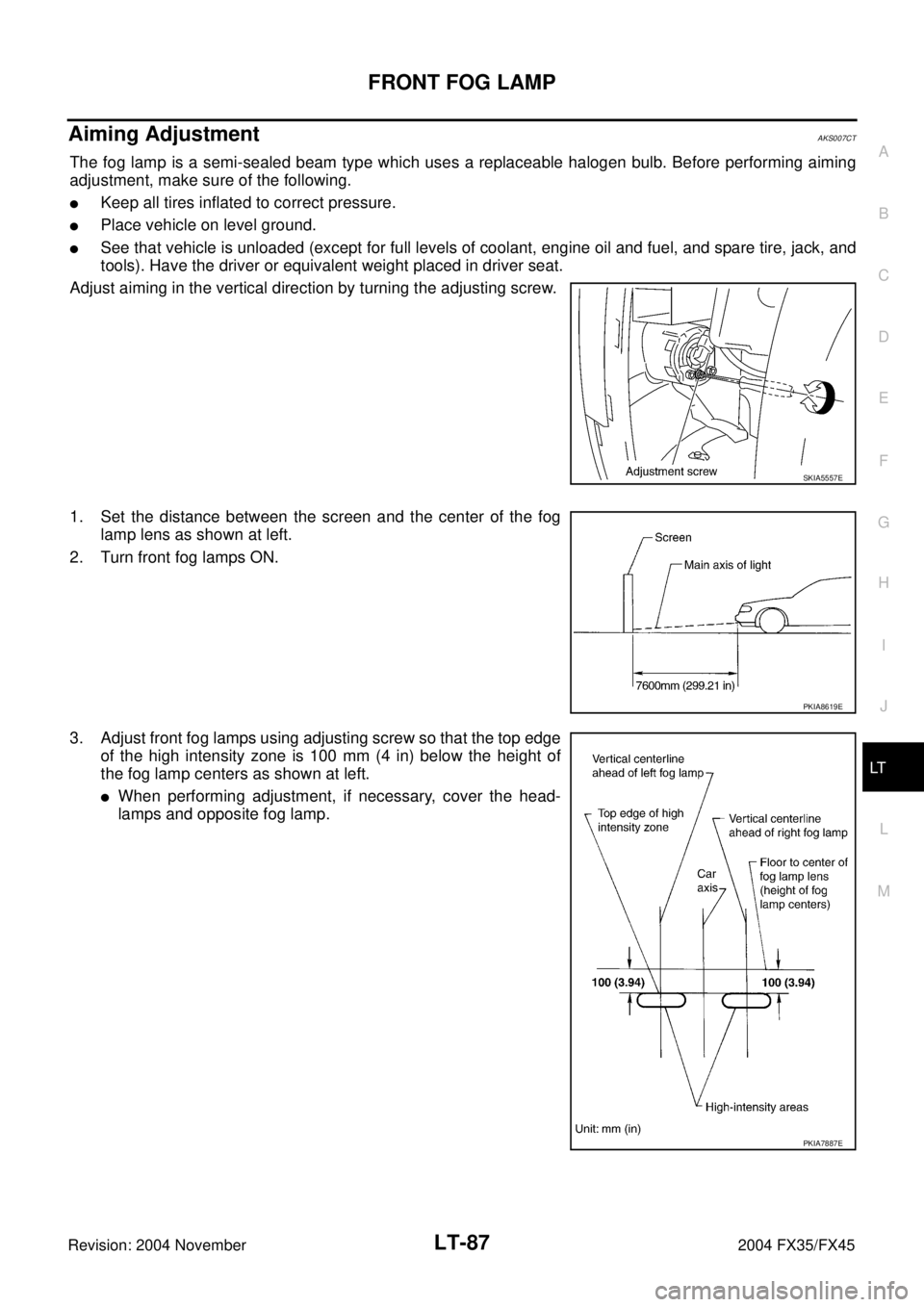
Aiming AdjustmentAKS007CT
The fog lamp is a semi-sealed beam type which uses a replaceable halogen bulb. Before performing aiming
adjustment, make sure of the following.
�Keep all tires inflated to correct pressure.
�Place vehicle on level ground.
�See that vehicle is unloaded (except for full levels of coolant, engine oil and fuel, and spare tire, jack, and
tools). Have the driver or equivalent weight placed in driver seat.
Adjust aiming in the vertical direction by turning the adjusting screw.
1. Set the distance between the screen and the center of the fog
lamp lens as shown at left.
2. Turn front fog lamps ON.
3. Adjust front fog lamps using adjusting screw so that the top edge
of the high intensity zone is 100 mm (4 in) below the height of
the fog lamp centers as shown at left.
�When performing adjustment, if necessary, cover the head-
lamps and opposite fog lamp.
SKIA5557E
PKIA8619E
PKIA7887E
Page 3667 of 4449

LT-112
COMBINATION SWITCH
Revision: 2004 November 2004 FX35/FX45
4. Touch “COMB SW”.
DATA MONITOR
Operation Procedure
1. Touch “COMB SW” on “SELECT TEST ITEM” screen.
2. Touch “DATA MONITOR” on “SELECT DIAG MODE” screen.
3. Touch either “ALL SIGNALS” or “SELECTION FROM MENU” on “DATA MONITOR” screen.
4. Touch “START”.
5. When “SELECTION FROM MENU” is selected, touch items to be monitored. When “ALL SIGNALS” is
selected, all the signals will be monitored.
6. Touch “RECORD” while monitoring, then the status of the monitored item can be recorded. To stop
recording, touch “STOP”.
Display Item List
PKIA5223E
ALL SIGNALS Monitors all the signals.
SELECTION FROM MENU Selects and monitors individual signal.
Monitor item name
“OPERATION OR UNIT”Contents
TURN SIGNAL R “ON/OFF” Displays “Turn Right (ON)/Other (OFF)” status, determined from lighting switch signal.
TURN SIGNAL L “ON/OFF” Displays “Turn Left (ON)/Other (OFF)” status, determined from lighting switch signal.
HI BEAM SW “ON/OFF”Displays status (high beam switch: ON/Others: OFF) of high beam switch judged from lighting
switch signal.
HEAD LAMP SW 1 “ON/OFF” Displays “Headlamp switch 1 (ON)/Other (OFF)” status, determined from lighting switch signal.
HEAD LAMP SW 2 “ON/OFF”Displays status (headlamp switch 2: ON/Others: OFF) of headlamp switch 2 judged from lighting
switch signal.
TAIL LAMP SW “ON/OFF”Displays status (lighting switch 1st position: ON/Others: OFF) of lighting switch judged from light-
ing switch signal.
PASSING SW “ON/OFF”Displays status (flash-to-pass switch: ON/Others: OFF) of flash-to-pass switch judged from light-
ing switch signal.
AUTO LIGHT SW “ON/OFF” Displays “Auto light switch (ON)/Other (OFF)” status, determined from lighting switch signal.
FR FOG SW “ON/OFF” Displays “Front fog lamp switch (ON)/Other (OFF)” status, determined from lighting switch signal.
FR WIPER HI “ON/OFF” Displays “Front Wiper HI (ON)/Other (OFF)” status, determined from wiper switch signal.
FR WIPER LOW “ON/OFF” Displays “Front Wiper LOW (ON)/Other (OFF)” status, determined from wiper switch signal.
FR WIPER INT “ON/OFF” Displays “Front Wiper INT (ON)/Other (OFF)” status, determined from wiper switch signal.
FR WASHER SW “ON/OFF” Displays “Front Washer Switch (ON)/Other (OFF)” status, determined from wiper switch signal.
INT VOLUME [1 - 7] Displays intermittent operation knob setting (1 - 7), determined from wiper switch signal.
RR WIPER ON “ON/OFF” Displays “rear Wiper (ON)/Other (OFF)” status as judged from wiper switch signal.
RR WIPER INT “ON/OFF” Displays “rear Wiper INT (ON)/Other (OFF)” status as judged from wiper switch signal.
RR WASHER SW “ON/OFF” Displays “rear Washer Switch (ON)/Other (OFF)” status as judged from wiper switch signal.
Page 3668 of 4449

COMBINATION SWITCH
LT-113
C
D
E
F
G
H
I
J
L
MA
B
LT
Revision: 2004 November 2004 FX35/FX45
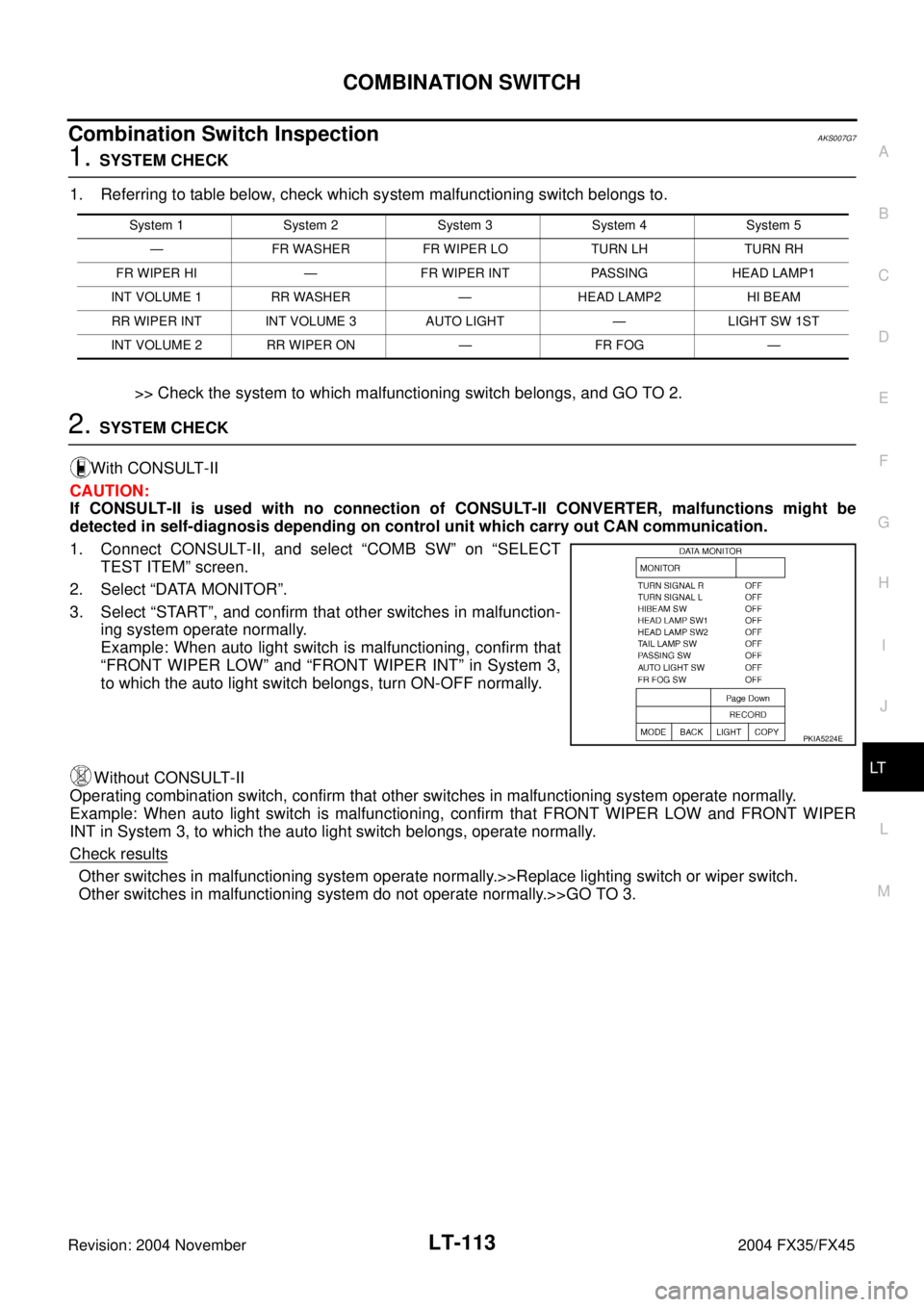
Combination Switch InspectionAKS007G7
1. SYSTEM CHECK
1. Referring to table below, check which system malfunctioning switch belongs to.
>> Check the system to which malfunctioning switch belongs, and GO TO 2.
2. SYSTEM CHECK
With CONSULT-II
CAUTION:
If CONSULT-II is used with no connection of CONSULT-II CONVERTER, malfunctions might be
detected in self-diagnosis depending on control unit which carry out CAN communication.
1. Connect CONSULT-II, and select “COMB SW” on “SELECT
TEST ITEM” screen.
2. Select “DATA MONITOR”.
3. Select “START”, and confirm that other switches in malfunction-
ing system operate normally.
Example: When auto light switch is malfunctioning, confirm that
“FRONT WIPER LOW” and “FRONT WIPER INT” in System 3,
to which the auto light switch belongs, turn ON-OFF normally.
Without CONSULT-II
Operating combination switch, confirm that other switches in malfunctioning system operate normally.
Example: When auto light switch is malfunctioning, confirm that FRONT WIPER LOW and FRONT WIPER
INT in System 3, to which the auto light switch belongs, operate normally.
Check results
Other switches in malfunctioning system operate normally.>>Replace lighting switch or wiper switch.
Other switches in malfunctioning system do not operate normally.>>GO TO 3.
System 1 System 2 System 3 System 4 System 5
— FR WASHER FR WIPER LO TURN LH TURN RH
FR WIPER HI — FR WIPER INT PASSING HEAD LAMP1
INT VOLUME 1 RR WASHER — HEAD LAMP2 HI BEAM
RR WIPER INT INT VOLUME 3 AUTO LIGHT — LIGHT SW 1ST
INT VOLUME 2 RR WIPER ON — FR FOG —
PKIA5224E
Page 4115 of 4449

SC-26
CHARGING SYSTEM
Revision: 2004 November 2004 FX35/FX45
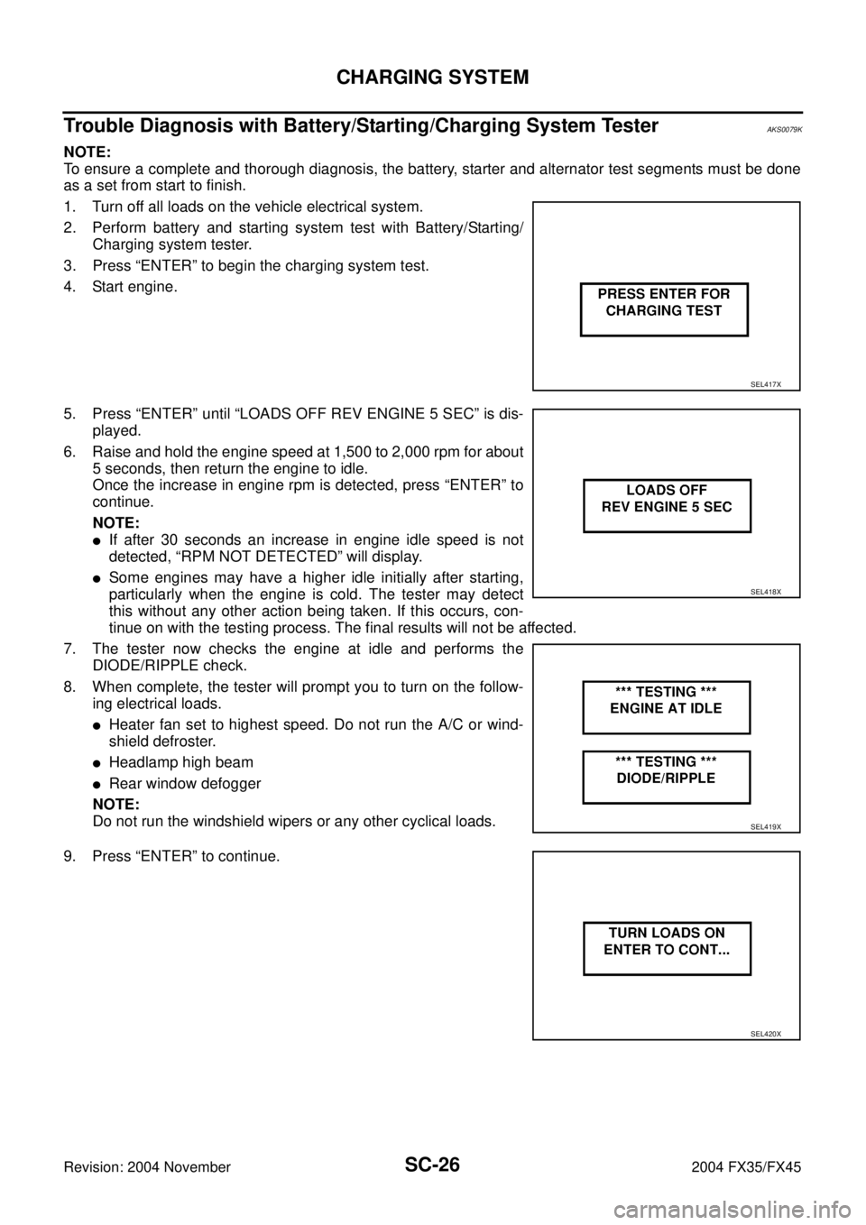
Trouble Diagnosis with Battery/Starting/Charging System TesterAKS0079K
NOTE:
To ensure a complete and thorough diagnosis, the battery, starter and alternator test segments must be done
as a set from start to finish.
1. Turn off all loads on the vehicle electrical system.
2. Perform battery and starting system test with Battery/Starting/
Charging system tester.
3. Press “ENTER” to begin the charging system test.
4. Start engine.
5. Press “ENTER” until “LOADS OFF REV ENGINE 5 SEC” is dis-
played.
6. Raise and hold the engine speed at 1,500 to 2,000 rpm for about
5 seconds, then return the engine to idle.
Once the increase in engine rpm is detected, press “ENTER” to
continue.
NOTE:
�If after 30 seconds an increase in engine idle speed is not
detected, “RPM NOT DETECTED” will display.
�Some engines may have a higher idle initially after starting,
particularly when the engine is cold. The tester may detect
this without any other action being taken. If this occurs, con-
tinue on with the testing process. The final results will not be affected.
7. The tester now checks the engine at idle and performs the
DIODE/RIPPLE check.
8. When complete, the tester will prompt you to turn on the follow-
ing electrical loads.
�Heater fan set to highest speed. Do not run the A/C or wind-
shield defroster.
�Headlamp high beam
�Rear window defogger
NOTE:
Do not run the windshield wipers or any other cyclical loads.
9. Press “ENTER” to continue.
SEL417X
SEL418X
SEL419X
SEL420X