Page 286 of 4449

TROUBLE DIAGNOSIS FOR SYMPTOMS
AT-209
D
E
F
G
H
I
J
K
L
MA
B
AT
Revision: 2004 November 2004 FX35/FX45
THROTTLE POSITION SENSOR" , AT- 11 6 , "DTC P0720 VEHICLE SPEED SENSOR A/T (REV-
OLUTION SENSOR)" , AT- 1 4 5 , "DTC P1721 VEHICLE SPEED SENSOR MTR" .
NO >> GO TO 3.
3. CHECK A/T FLUID LEVEL
Check A/T fluid level. Refer to AT- 1 2 , "
Checking A/T Fluid" .
OK or NG
OK >> GO TO 4.
NG >> Refill ATF.
4. CHECK LINE PRESSURE
Check line pressure at the engine stall point. Refer to AT- 5 2 , "
LINE
PRESSURE TEST" .
OK or NG
OK >> GO TO 7.
NG - 1 >> Line pressure high. GO TO 5.
NG - 2 >> Line pressure low. GO TO 6.
5. DETECT MALFUNCTIONING ITEM
1. Check control valve with TCM. Refer to AT- 2 4 2 , "
Control Valve with TCM and A/T Fluid Temperature Sen-
sor 2" .
2. Disassemble A/T. Refer to AT- 2 8 6 , "
DISASSEMBLY" .
3. Check the following items:
–Oil pump assembly. Refer to AT- 3 0 3 , "Oil Pump" .
OK or NG
OK >> GO TO 7.
NG >> Repair or replace damaged parts.
6. DETECT MALFUNCTIONING ITEM
1. Check control valve with TCM. Refer to AT- 2 4 2 , "
Control Valve with TCM and A/T Fluid Temperature Sen-
sor 2" .
2. Disassemble A/T. Refer to AT- 2 8 6 , "
DISASSEMBLY" .
3. Check the following items:
–Oil pump assembly. Refer to AT- 3 0 3 , "Oil Pump" .
–Power train system. Refer to AT- 2 8 6 , "DISASSEMBLY" .
–Transmission case. Refer to AT- 2 8 6 , "DISASSEMBLY" .
OK or NG
OK >> GO TO 7.
NG >> Repair or replace damaged parts.
SAT638A
SAT494G
Page 289 of 4449

AT-212
TROUBLE DIAGNOSIS FOR SYMPTOMS
Revision: 2004 November 2004 FX35/FX45
5. DETECT MALFUNCTIONING ITEM
1. Check control valve with TCM. Refer to AT- 2 4 2 , "
Control Valve with TCM and A/T Fluid Temperature Sen-
sor 2" .
2. Disassemble A/T. Refer to AT- 2 8 6 , "
DISASSEMBLY" .
3. Check the following items:
–Oil pump assembly. Refer to AT- 3 0 3 , "Oil Pump" .
OK or NG
OK >> GO TO 7.
NG >> Repair or replace damaged parts.
6. DETECT MALFUNCTIONING ITEM
1. Check control valve with TCM. Refer to AT- 2 4 2 , "
Control Valve with TCM and A/T Fluid Temperature Sen-
sor 2" .
2. Disassemble A/T. Refer to AT- 2 8 6 , "
DISASSEMBLY" .
3. Check the following items:
–Oil pump assembly. Refer to AT- 3 0 3 , "Oil Pump" .
–Power train system. Refer to AT- 2 8 6 , "DISASSEMBLY" .
–Transmission case. Refer to AT- 2 8 6 , "DISASSEMBLY" .
OK or NG
OK >> GO TO 7.
NG >> Repair or replace damaged parts.
7. CHECK A/T FLUID CONDITION
1. Remove oil pan. Refer to AT- 2 4 2 , "
Control Valve with TCM and A/T Fluid Temperature Sensor 2" .
2. Check A/T fluid condition. Refer to AT- 5 1 , "
Fluid Condition
Check" .
OK or NG
OK >> GO TO 8.
NG >> GO TO 11.
8. DETECT MALFUNCTIONING ITEM
�Check the malfunction items. If any items are damaged, repair or replace damaged parts. Refer to AT- 6 5 ,
"Symptom Chart" (Symptom No.12).
OK or NG
OK >> GO TO 9.
NG >> Repair or replace damaged parts.
9. CHECK SYMPTOM
Check again. Refer to AT- 5 7 , "
Cruise Test - Part 1" , AT- 6 0 , "Cruise Test - Part 2" .
OK or NG
OK >>INSPECTION END
NG >> GO TO 10.
SCIA5199E
Page 291 of 4449

AT-214
TROUBLE DIAGNOSIS FOR SYMPTOMS
Revision: 2004 November 2004 FX35/FX45
3. CHECK A/T FLUID LEVEL
Check A/T fluid level. Refer to AT- 1 2 , "
Checking A/T Fluid" .
OK or NG
OK >> GO TO 4.
NG >> Refill ATF.
4. CHECK LINE PRESSURE
Check line pressure at the engine stall point. Refer to AT- 5 2 , "
LINE
PRESSURE TEST" .
OK or NG
OK >> GO TO 7.
NG - 1 >> Line pressure high. GO TO 5.
NG - 2 >> Line pressure low. GO TO 6.
5. DETECT MALFUNCTIONING ITEM
1. Check control valve with TCM. Refer to AT- 2 4 2 , "
Control Valve with TCM and A/T Fluid Temperature Sen-
sor 2" .
2. Disassemble A/T. Refer to AT- 2 8 6 , "
DISASSEMBLY" .
3. Check the following items:
–Oil pump assembly. Refer to AT- 3 0 3 , "Oil Pump" .
OK or NG
OK >> GO TO 7.
NG >> Repair or replace damaged parts.
6. DETECT MALFUNCTIONING ITEM
1. Check control valve with TCM. Refer to AT- 2 4 2 , "
Control Valve with TCM and A/T Fluid Temperature Sen-
sor 2" .
2. Disassemble A/T. Refer to AT- 2 8 6 , "
DISASSEMBLY" .
3. Check the following items:
–Oil pump assembly. Refer to AT- 3 0 3 , "Oil Pump" .
–Power train system. Refer to AT- 2 8 6 , "DISASSEMBLY" .
–Transmission case. Refer to AT- 2 8 6 , "DISASSEMBLY" .
OK or NG
OK >> GO TO 7.
NG >> Repair or replace damaged parts.
SAT638A
SAT494G
Page 294 of 4449

TROUBLE DIAGNOSIS FOR SYMPTOMS
AT-217
D
E
F
G
H
I
J
K
L
MA
B
AT
Revision: 2004 November 2004 FX35/FX45
4. DETECT MALFUNCTIONING ITEM
1. Check control valve with TCM. Refer to AT- 2 4 2 , "
Control Valve with TCM and A/T Fluid Temperature Sen-
sor 2" .
2. Disassemble A/T. Refer to AT- 2 8 6 , "
DISASSEMBLY" .
3. Check the following items:
–Oil pump assembly. Refer to AT- 3 0 3 , "Oil Pump" .
OK or NG
OK >> GO TO 6.
NG >> Repair or replace damaged parts.
5. DETECT MALFUNCTIONING ITEM
1. Check control valve with TCM. Refer to AT- 2 4 2 , "
Control Valve with TCM and A/T Fluid Temperature Sen-
sor 2" .
2. Disassemble A/T. Refer to AT- 2 8 6 , "
DISASSEMBLY" .
3. Check the following items:
–Oil pump assembly. Refer to AT- 3 0 3 , "Oil Pump" .
–Power train system. Refer to AT- 2 8 6 , "DISASSEMBLY" .
–Transmission case. Refer to AT- 2 8 6 , "DISASSEMBLY" .
OK or NG
OK >> GO TO 6.
NG >> Repair or replace damaged parts.
6. CHECK A/T FLUID CONDITION
1. Remove oil pan. Refer to AT- 2 4 2 , "
Control Valve with TCM and A/T Fluid Temperature Sensor 2" .
2. Check A/T fluid condition. Refer to AT- 5 1 , "
Fluid Condition
Check" .
OK or NG
OK >> GO TO 7.
NG >> GO TO 10.
7. DETECT MALFUNCTIONING ITEM
�Check the malfunction items. If any items are damaged, repair or replace damaged parts. Refer to AT- 6 5 ,
"Symptom Chart" (Symptom No.24).
OK or NG
OK >> GO TO 8.
NG >> Repair or replace damaged parts.
8. CHECK SYMPTOM
Check again. Refer to AT- 5 7 , "
Cruise Test - Part 1" .
OK or NG
OK >>INSPECTION END
NG >> GO TO 9.
SCIA5199E
Page 323 of 4449

AT-246
ON-VEHICLE SERVICE
Revision: 2004 November 2004 FX35/FX45
Installation
CAUTION:
After completing installation, check A/T fluid leakage and fluid level. Refer to AT- 1 2 , "
Changing A/T
Fluid" , AT- 1 2 , "Checking A/T Fluid" .
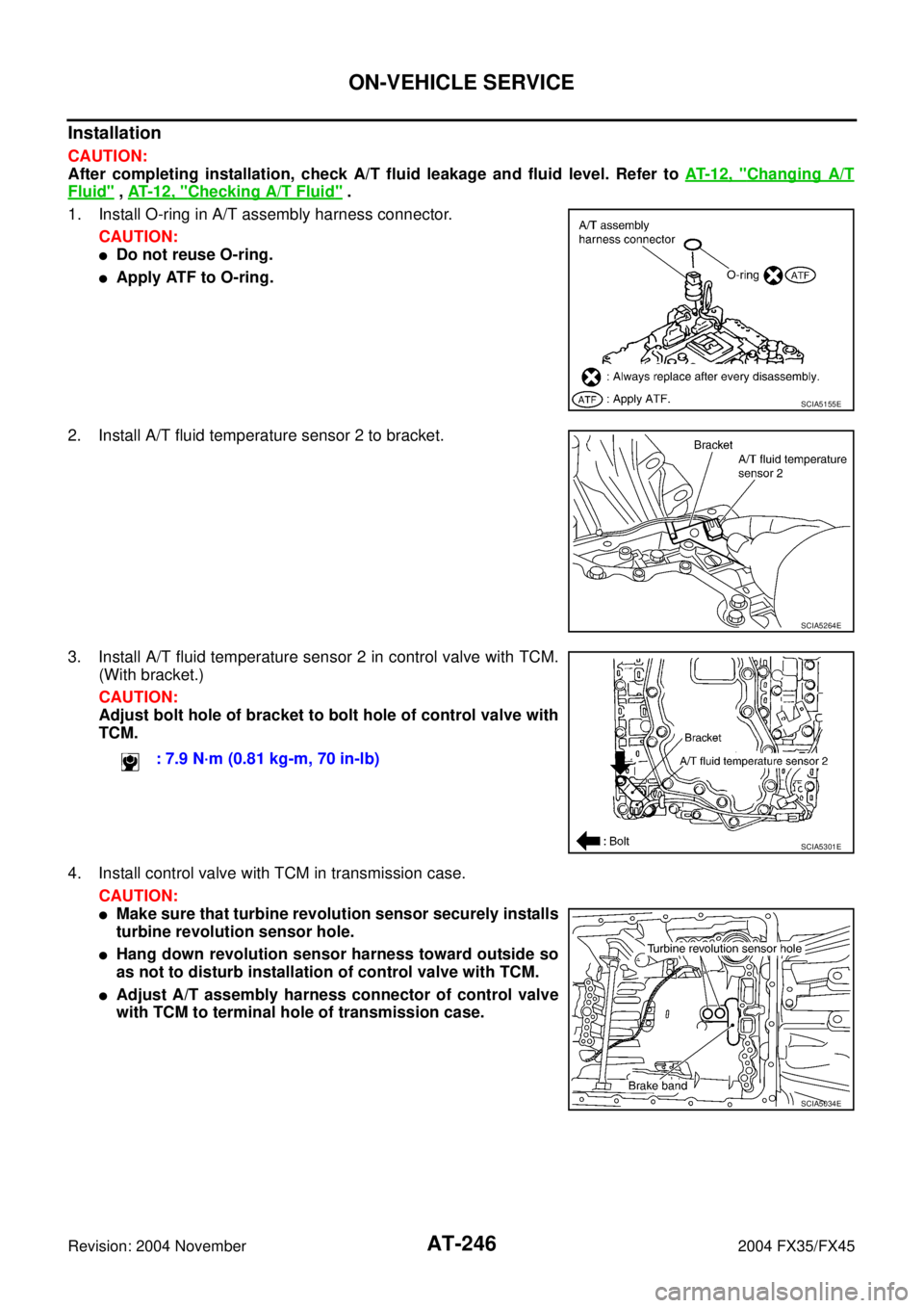
1. Install O-ring in A/T assembly harness connector.
CAUTION:
�Do not reuse O-ring.
�Apply ATF to O-ring.
2. Install A/T fluid temperature sensor 2 to bracket.
3. Install A/T fluid temperature sensor 2 in control valve with TCM.
(With bracket.)
CAUTION:
Adjust bolt hole of bracket to bolt hole of control valve with
TCM.
4. Install control valve with TCM in transmission case.
CAUTION:
�Make sure that turbine revolution sensor securely installs
turbine revolution sensor hole.
�Hang down revolution sensor harness toward outside so
as not to disturb installation of control valve with TCM.
�Adjust A/T assembly harness connector of control valve
with TCM to terminal hole of transmission case.
SCIA5155E
SCIA5264E
: 7.9 N·m (0.81 kg-m, 70 in-lb)
SCIA5301E
SCIA5034E
Page 328 of 4449
ON-VEHICLE SERVICE
AT-251
D
E
F
G
H
I
J
K
L
MA
B
AT
Revision: 2004 November 2004 FX35/FX45
Installation
CAUTION:
After completing installation, check A/T fluid leakage and fluid level. Refer to AT- 1 2 , "
Changing A/T
Fluid" , AT- 1 2 , "Checking A/T Fluid" .
1. Install A/T fluid temperature sensor 2 to bracket.
2. Install A/T fluid temperature sensor 2 in control valve with TCM.
(With bracket.)
3. Connect A/T fluid temperature sensor 2 connector.
4. Securely fasten A/T fluid temperature sensor 2 harness with ter-
minal clip.
5. Install oil pan to transmission case.
a. Install oil pan gasket to oil pan.
CAUTION:
�Do not reuse oil pan gasket.
�Install it in the direction to align hole positions.
�Complete remove all moisture, oil and old gasket, etc. from oil pan mounting surface.
SCIA5264E
: 7.9 N·m (0.81 kg-m, 70 in-lb)
SCIA5302E
SCIA5023E
SCIA5146E
Page 336 of 4449

ON-VEHICLE SERVICE
AT-259
D
E
F
G
H
I
J
K
L
MA
B
AT
Revision: 2004 November 2004 FX35/FX45
Rear Oil SealACS007H1
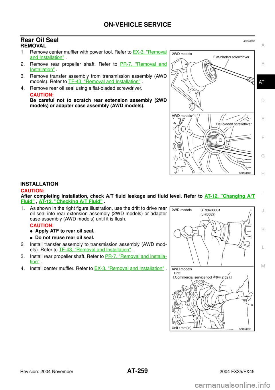
REMOVAL
1. Remove center muffler with power tool. Refer to EX-3, "Removal
and Installation" .
2. Remove rear propeller shaft. Refer to PR-7, "
Removal and
Installation" .
3. Remove transfer assembly from transmission assembly (AWD
models). Refer to TF-43, "
Removal and Installation" .
4. Remove rear oil seal using a flat-bladed screwdriver.
CAUTION:
Be careful not to scratch rear extension assembly (2WD
models) or adapter case assembly (AWD models).
INSTALLATION
CAUTION:
After completing installation, check A/T fluid leakage and fluid level. Refer to AT- 1 2 , "
Changing A/T
Fluid" , AT- 1 2 , "Checking A/T Fluid" .
1. As shown in the right figure illustration, use the drift to drive rear
oil seal into rear extension assembly (2WD models) or adapter
case assembly (AWD models) until it is flush.
CAUTION:
�Apply ATF to rear oil seal.
�Do not reuse rear oil seal.
2. Install transfer assembly to transmission assembly (AWD mod-
els). Refer to TF-43, "
Removal and Installation" .
3. Install rear propeller shaft. Refer to PR-7, "
Removal and Installa-
tion" .
4. Install center muffler. Refer to EX-3, "
Removal and Installation" .
SCIA5410E
SCIA5411E
Page 339 of 4449

AT-262
ON-VEHICLE SERVICE
Revision: 2004 November 2004 FX35/FX45
INSTALLATION
CAUTION:
After completing installation, check A/T fluid leakage and fluid level. Refer to AT- 1 2 , "
Changing A/T
Fluid" , AT- 1 2 , "Checking A/T Fluid" .
1. Install revolution sensor in transmission case.
CAUTION:
�Do not subject it to impact by dropping or hitting it.
�Do not disassemble.
�Do not allow metal filings, etc. to get on the sensor's front
edge magnetic area.
�Do not place in an area affected by magnetism.
2. Connect revolution sensor connector.
3. Securely fasten revolution sensor harness with clips.
4. Apply recommended sealant (Genuine Anaerobic Liquid Gasket
or equivalent. Refer to GI-48, "
Recommended Chemical Prod-
ucts and Sealants" .) to rear extension assembly as shown in
the figure.
CAUTION:
Completely remove all moisture, oil and old sealant, etc.
from transmission case and rear extension assembly
mounting surfaces.
5. Install rear extension assembly to transmission case. (With nee-
dle bearing.): 5.8 N·m (0.59 kg-m, 51 in-lb)
SCIA3997E
SCIA3969E
SCIA5212E
SCIA3431E