Page 3118 of 4449
HOW TO USE THIS MANUAL
GI-15
C
D
E
F
G
H
I
J
K
L
MB
GI
Revision: 2004 November 2004 FX35/FX45
How to Read Wiring DiagramsAAS000E2
CONNECTOR SYMBOLS
Most of connector symbols in wiring diagrams are shown from the terminal side.
�Connector symbols shown from the terminal side are enclosed
by a single line and followed by the direction mark.
�Connector symbols shown from the harness side are enclosed
by a double line and followed by the direction mark.
�Certain systems and components, especially those related to
OBD, may use a new style slide-locking type harness connector.
For description and how to disconnect, refer to PG section,
“Description”, “HARNESS CONNECTOR”.
�Male and female terminals
Connector guides for male terminals are shown in black and
female terminals in white in wiring diagrams.
SAIA0257E
SGI363
Page 3119 of 4449
GI-16
HOW TO USE THIS MANUAL
Revision: 2004 November 2004 FX35/FX45
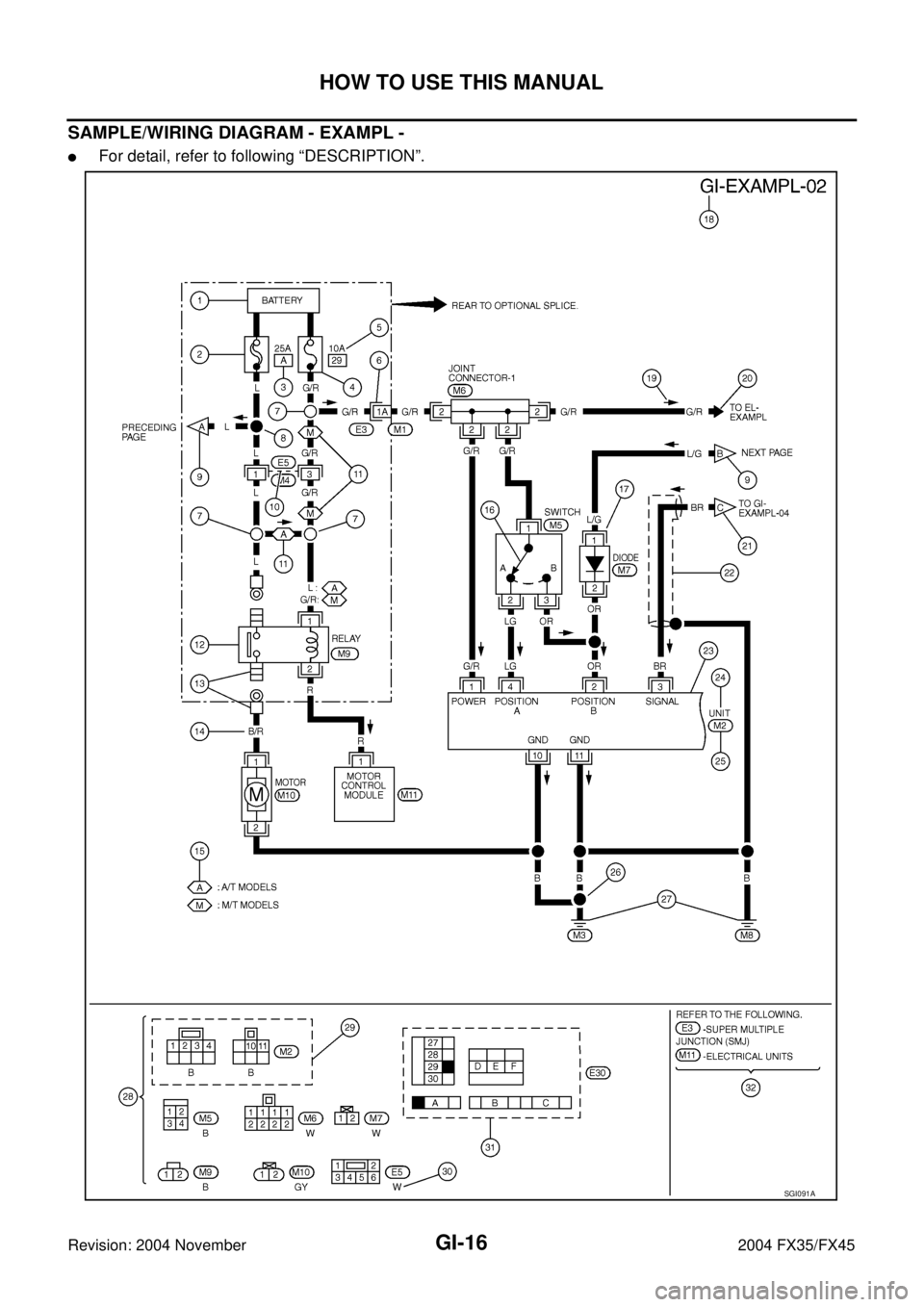
SAMPLE/WIRING DIAGRAM - EXAMPL -
�For detail, refer to following “DESCRIPTION”.
SGI091A
Page 3121 of 4449

GI-18
HOW TO USE THIS MANUAL
Revision: 2004 November 2004 FX35/FX45
14 Wire color
�This shows a code for the color of the wire.
B = Black
W = White
R = Red
G = Green
L = Blue
Y = Yellow
LG = Light GreenBR = Brown
OR or O = Orange
P = Pink
PU or V (Violet) = Purple
GY or GR = Gray
SB = Sky Blue
CH = Dark Brown
DG = Dark Green
When the wire color is striped, the base color is given first, followed by the stripe color as shown
below:
Example: L/W = Blue with White Stripe
15 Option description
�This shows a description of the option abbreviation used on the page.
16 Switch
�This shows that continuity exists between terminals 1 and 2 when the switch is in the A posi-
tion. Continuity exists between terminals 1 and 3 when the switch is in the B position.
17 Assembly parts
�Connector terminal in component shows that it is a harness incorporated assembly.
18 Cell code
�This identifies each page of the wiring diagram by section, system and wiring diagram page
number.
19 Current flow arrow
�Arrow indicates electric current flow, especially where the direction of standard flow (vertically
downward or horizontally from left to right) is difficult to follow.
�A double arrow “ ” shows that current can flow in either direction depending on cir-
cuit operation.
20 System branch
�This shows that the system branches to another system identified by cell code (section and
system).
21 Page crossing
�This arrow shows that the circuit continues to another page identified by cell code.
�The C will match with the C on another page within the system other than the next or preced-
ing pages.
22 Shielded line
�The line enclosed by broken line circle shows shield wire.
23Component box in
wave line
�This shows that another part of the component is also shown on another page (indicated by
wave line) within the system.
24 Component name
�This shows the name of a component.
25 Connector number
�This shows the connector number.
�The letter shows which harness the connector is located in.
�Example: M : main harness. For detail and to locate the connector, refer to PG section "Main
Harness", “Harness Layout”. A coordinate grid is included for complex harnesses to aid in
locating connectors.
26 Ground (GND)
�The line spliced and grounded under wire color shows that ground line is spliced at the
grounded connector.
27 Ground (GND)
�This shows the ground connection. For detailed ground distribution information, refer to
"Ground Distribution" in PG section.
28 Connector views
�This area shows the connector faces of the components in the wiring diagram on the page.
29 Common component
�Connectors enclosed in broken line show that these connectors belong to the same compo-
nent.
30 Connector color
�This shows a code for the color of the connector. For code meaning, refer to wire color codes,
Number 14 of this chart.
31Fusible link and fuse
box
�This shows the arrangement of fusible link(s) and fuse(s), used for connector views of
"POWER SUPPLY ROUTING" in PG section.
The open square shows current flow in, and the shaded square shows current flow out.
32 Reference area
�This shows that more information on the Super Multiple Junction (SMJ) and Joint Connectors
(J/C) exists on the PG section. Refer to "Reference Area" for details. Num-
berItem Description
Page 3122 of 4449
HOW TO USE THIS MANUAL
GI-19
C
D
E
F
G
H
I
J
K
L
MB
GI
Revision: 2004 November 2004 FX35/FX45
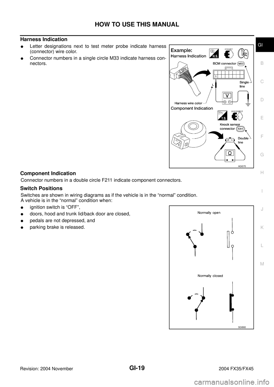
Harness Indication
�Letter designations next to test meter probe indicate harness
(connector) wire color.
�Connector numbers in a single circle M33 indicate harness con-
nectors.
Component Indication
Connector numbers in a double circle F211 indicate component connectors.
Switch Positions
Switches are shown in wiring diagrams as if the vehicle is in the “normal” condition.
A vehicle is in the “normal” condition when:
�ignition switch is “OFF”,
�doors, hood and trunk lid/back door are closed,
�pedals are not depressed, and
�parking brake is released.
AGI070
SGI860
Page 3123 of 4449
GI-20
HOW TO USE THIS MANUAL
Revision: 2004 November 2004 FX35/FX45
Detectable Lines and Non-Detectable Lines
In some wiring diagrams, two kinds of lines, representing wires, with different weight are used.
�A line with regular weight (wider line) represents a “detectable
line for DTC (Diagnostic Trouble Code)”. A “detectable line for
DTC” is a circuit in which ECM can detect its malfunctions with
the on board diagnostic system.
�A line with less weight (thinner line) represents a “non-detect-
able line for DTC”. A “non-detectable line for DTC” is a circuit in
which ECM cannot detect its malfunctions with the on board
diagnostic system.
SGI862-B
Page 3124 of 4449
HOW TO USE THIS MANUAL
GI-21
C
D
E
F
G
H
I
J
K
L
MB
GI
Revision: 2004 November 2004 FX35/FX45
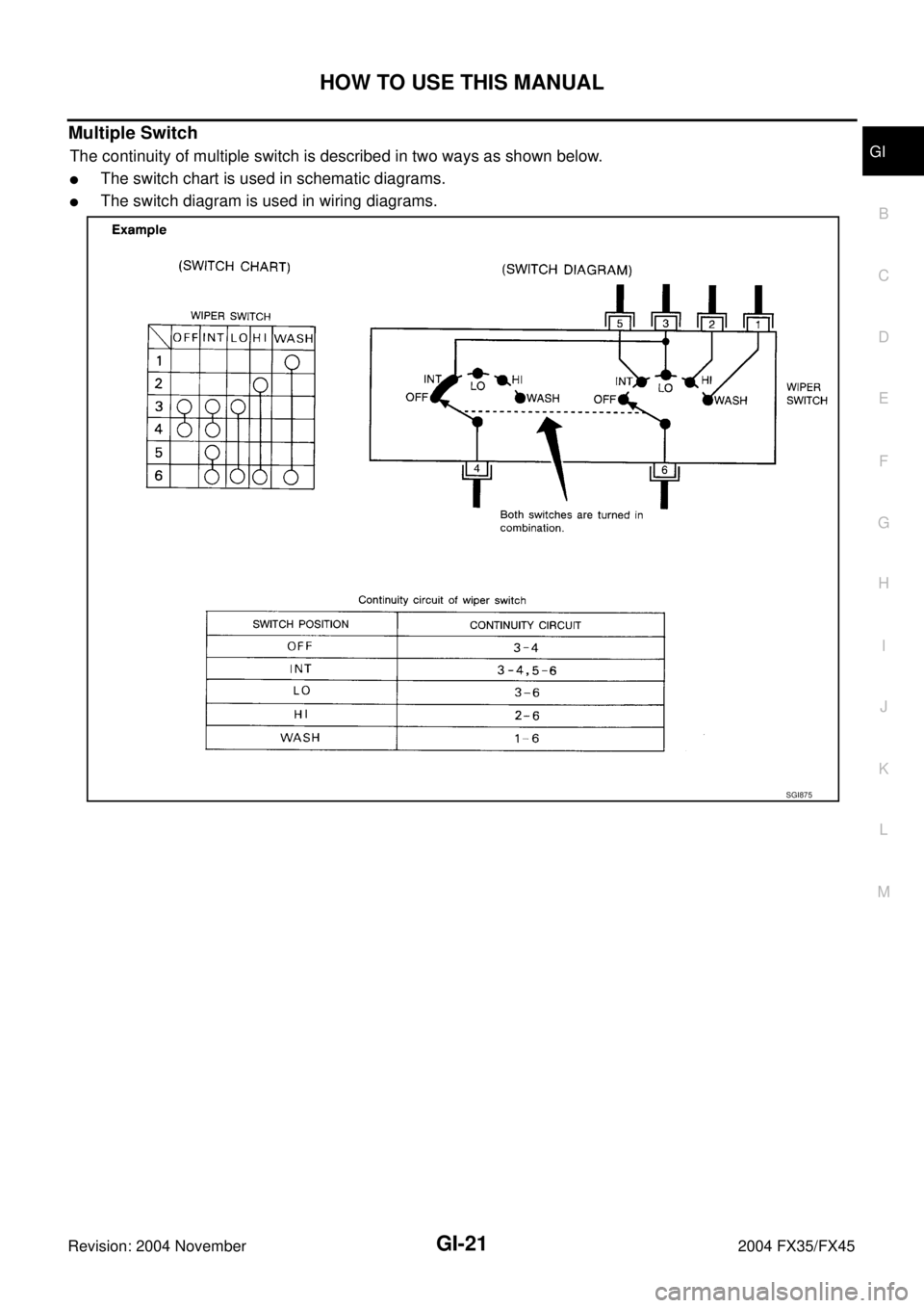
Multiple Switch
The continuity of multiple switch is described in two ways as shown below.
�The switch chart is used in schematic diagrams.
�The switch diagram is used in wiring diagrams.
SGI875
Page 3125 of 4449
GI-22
HOW TO USE THIS MANUAL
Revision: 2004 November 2004 FX35/FX45
Reference Area
The Reference Area of the wiring diagram contains references to additional electrical reference pages at the
end of the manual. If connector numbers and titles are shown in the Reference Area of the wiring diagram,
these connector symbols are not shown in the Connector Area.
SGI092A
Page 3131 of 4449

GI-28
SERVICE INFORMATION FOR ELECTRICAL INCIDENT
Revision: 2004 November 2004 FX35/FX45
�Freezing
�Water intrusion
�Electrical load
�Cold or hot start up
Get a thorough description of the incident from the customer. It is important for simulating the conditions of the
problem.
Vehicle Vibration
The problem may occur or become worse while driving on a rough road or when engine is vibrating (idle with
A/C on). In such a case, you will want to check for a vibration related condition. Refer to the following illustra-
tion.
CONNECTORS & HARNESS
Determine which connectors and wiring harness would affect the electrical system you are inspecting. Gently
shake each connector and harness while monitoring the system for the incident you are trying to duplicate.
This test may indicate a loose or poor electrical connection.
HINT
Connectors can be exposed to moisture. It is possible to get a thin film of corrosion on the connector termi-
nals. A visual inspection may not reveal this without disconnecting the connector. If the problem occurs inter-
mittently, perhaps the problem is caused by corrosion. It is a good idea to disconnect, inspect and clean the
terminals on related connectors in the system.
SENSORS & RELAYS
Gently apply a slight vibration to sensors and relays in the system you are inspecting.
This test may indicate a loose or poorly mounted sensor or relay.
ENGINE COMPARTMENT
There are several reasons a vehicle or engine vibration could cause an electrical complaint. Some of the
things to check for are:
�Connectors not fully seated.
�Wiring harness not long enough and is being stressed due to engine vibrations or rocking.
�Wires laying across brackets or moving components.
�Loose, dirty or corroded ground wires.
�Wires routed too close to hot components.
To inspect components under the hood, start by verifying the integrity of ground connections. (Refer to Ground
Inspection described later.) First check that the system is properly grounded. Then check for loose connection
by gently shaking the wiring or components as previously explained. Using the wiring diagrams inspect the
wiring for continuity.
BEHIND THE INSTRUMENT PANEL
An improperly routed or improperly clamped harness can become pinched during accessory installation. Vehi-
cle vibration can aggravate a harness which is routed along a bracket or near a screw.
SGI839