2004 INFINITI FX35 service indicator
[x] Cancel search: service indicatorPage 3275 of 4449
IDX-2
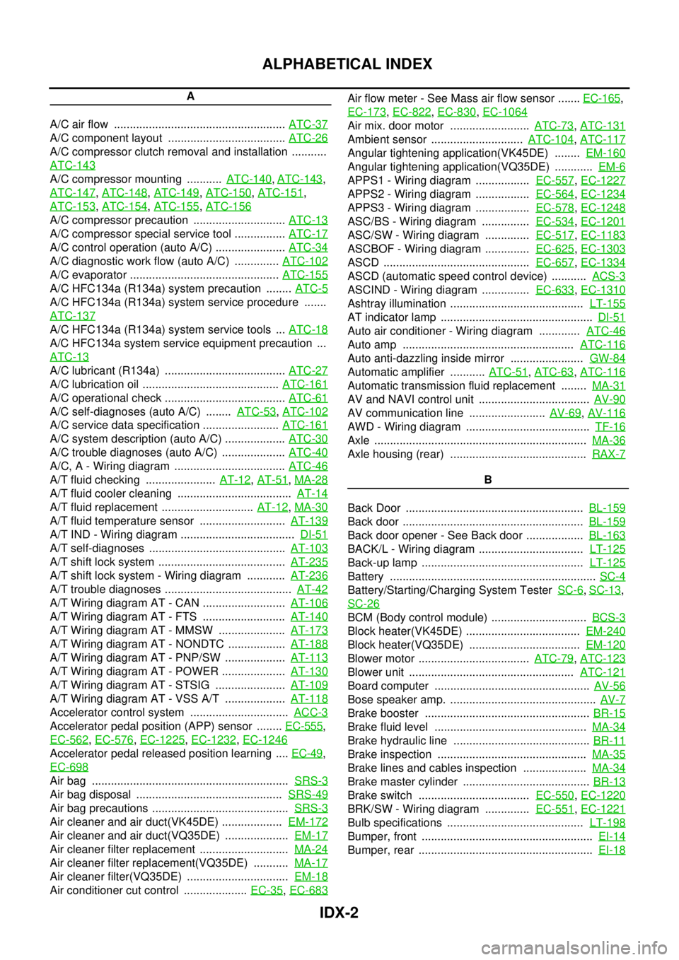
ALPHABETICAL INDEX
A
A/C air flow ...................................................... ATC-37
A/C component layout ..................................... ATC-26
A/C compressor clutch removal and installation ...........
ATC-143
A/C compressor mounting ........... ATC-140, ATC-143,
ATC-147
, ATC-148, ATC-149, ATC-150, ATC-151,
ATC-153
, ATC-154, ATC-155, ATC-156
A/C compressor precaution ............................. ATC-13
A/C compressor special service tool ................ ATC-17
A/C control operation (auto A/C) ...................... ATC-34
A/C diagnostic work flow (auto A/C) .............. ATC-102
A/C evaporator ............................................... ATC-155
A/C HFC134a (R134a) system precaution ........ ATC-5
A/C HFC134a (R134a) system service procedure .......
ATC-137
A/C HFC134a (R134a) system service tools ... ATC-18
A/C HFC134a system service equipment precaution ...
ATC-13
A/C lubricant (R134a) ...................................... ATC-27
A/C lubrication oil ........................................... ATC-161
A/C operational check ...................................... ATC-61
A/C self-diagnoses (auto A/C) ........ ATC-53, ATC-102
A/C service data specification ........................ ATC-161
A/C system description (auto A/C) ................... ATC-30
A/C trouble diagnoses (auto A/C) .................... ATC-40
A/C, A - Wiring diagram ................................... ATC-46
A/T fluid checking ...................... AT-12, AT-51, MA-28
A/T fluid cooler cleaning .................................... AT-14
A/T fluid replacement ............................. AT-12, MA-30
A/T fluid temperature sensor ........................... AT-139
A/T IND - Wiring diagram .................................... DI-51
A/T self-diagnoses ........................................... AT-103
A/T shift lock system ........................................ AT-235
A/T shift lock system - Wiring diagram ............ AT-236
A/T trouble diagnoses ........................................ AT-42
A/T Wiring diagram AT - CAN .......................... AT-106
A/T Wiring diagram AT - FTS .......................... AT-140
A/T Wiring diagram AT - MMSW ..................... AT-173
A/T Wiring diagram AT - NONDTC .................. AT-188
A/T Wiring diagram AT - PNP/SW ................... AT-113
A/T Wiring diagram AT - POWER .................... AT-130
A/T Wiring diagram AT - STSIG ...................... AT-109
A/T Wiring diagram AT - VSS A/T ................... AT-118
Accelerator control system ............................... ACC-3
Accelerator pedal position (APP) sensor ........ EC-555,
EC-562
, EC-576, EC-1225, EC-1232, EC-1246
Accelerator pedal released position learning .... EC-49,
EC-698
Air bag .............................................................. SRS-3
Air bag disposal .............................................. SRS-49
Air bag precautions ........................................... SRS-3
Air cleaner and air duct(VK45DE) ................... EM-172
Air cleaner and air duct(VQ35DE) .................... EM-17
Air cleaner filter replacement ............................ MA-24
Air cleaner filter replacement(VQ35DE) ........... MA-17
Air cleaner filter(VQ35DE) ................................ EM-18
Air conditioner cut control .................... EC-35, EC-683
Air flow meter - See Mass air flow sensor ....... EC-165,
EC-173
, EC-822, EC-830, EC-1064
Air mix. door motor ......................... ATC-73, ATC-131
Ambient sensor ............................. ATC-104, ATC-117
Angular tightening application(VK45DE) ........ EM-160
Angular tightening application(VQ35DE) ............ EM-6
APPS1 - Wiring diagram ................. EC-557, EC-1227
APPS2 - Wiring diagram ................. EC-564, EC-1234
APPS3 - Wiring diagram ................. EC-578, EC-1248
ASC/BS - Wiring diagram ............... EC-534, EC-1201
ASC/SW - Wiring diagram .............. EC-517, EC-1183
ASCBOF - Wiring diagram .............. EC-625, EC-1303
ASCD .............................................. EC-657, EC-1334
ASCD (automatic speed control device) ........... ACS-3
ASCIND - Wiring diagram ............... EC-633, EC-1310
Ashtray illumination .......................................... LT-155
AT indicator lamp ................................................ DI-51
Auto air conditioner - Wiring diagram ............. ATC-46
Auto amp ...................................................... ATC-116
Auto anti-dazzling inside mirror ....................... GW-84
Automatic amplifier ........... ATC-51, ATC-63, ATC-116
Automatic transmission fluid replacement ........ MA-31
AV and NAVI control unit ................................... AV-90
AV communication line ........................ AV-69, AV-116
AWD - Wiring diagram ....................................... TF-16
Axle ................................................................... MA-36
Axle housing (rear) ........................................... RAX-7
B
Back Door ........................................................ BL-159
Back door ......................................................... BL-159
Back door opener - See Back door .................. BL-163
BACK/L - Wiring diagram ................................. LT-125
Back-up lamp ................................................... LT-125
Battery ................................................................. SC-4
Battery/Starting/Charging System Tester SC-6, SC-13,
SC-26
BCM (Body control module) .............................. BCS-3
Block heater(VK45DE) .................................... EM-240
Block heater(VQ35DE) ................................... EM-120
Blower motor ................................... ATC-79, ATC-123
Blower unit .................................................... ATC-121
Board computer ................................................. AV-56
Bose speaker amp. .............................................. AV-7
Brake booster .................................................... BR-15
Brake fluid level ................................................ MA-34
Brake hydraulic line ........................................... BR-11
Brake inspection ............................................... MA-35
Brake lines and cables inspection .................... MA-34
Brake master cylinder ........................................ BR-13
Brake switch ................................... EC-550, EC-1220
BRK/SW - Wiring diagram .............. EC-551, EC-1221
Bulb specifications ........................................... LT-198
Bumper, front ...................................................... EI-14
Bumper, rear ....................................................... EI-18
Page 3556 of 4449
LT-1
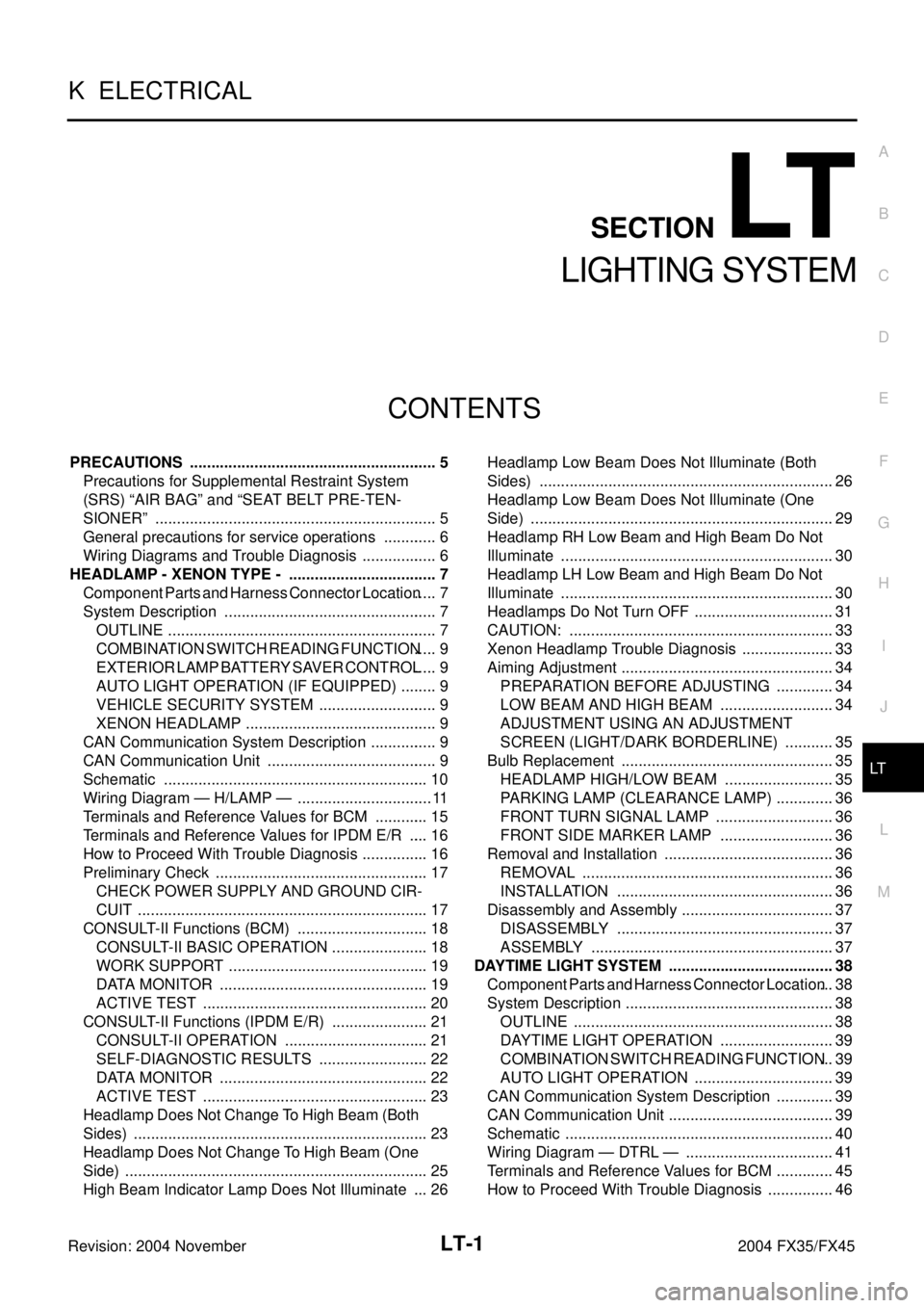
LIGHTING SYSTEM
K ELECTRICAL
CONTENTS
C
D
E
F
G
H
I
J
L
M
SECTION LT
A
B
LT
Revision: 2004 November 2004 FX35/FX45
LIGHTING SYSTEM
PRECAUTIONS .......................................................... 5
Precautions for Supplemental Restraint System
(SRS) “AIR BAG” and “SEAT BELT PRE-TEN-
SIONER” .................................................................. 5
General precautions for service operations ............. 6
Wiring Diagrams and Trouble Diagnosis .................. 6
HEADLAMP - XENON TYPE - ................................... 7
Component Parts and Harness Connector Location ..... 7
System Description .................................................. 7
OUTLINE ............................................................... 7
COMBINATION SWITCH READING FUNCTION ..... 9
EXTERIOR LAMP BATTERY SAVER CONTROL ..... 9
AUTO LIGHT OPERATION (IF EQUIPPED) ......... 9
VEHICLE SECURITY SYSTEM ............................ 9
XENON HEADLAMP ............................................. 9
CAN Communication System Description ................ 9
CAN Communication Unit ........................................ 9
Schematic .............................................................. 10
Wiring Diagram — H/LAMP — ................................ 11
Terminals and Reference Values for BCM ............. 15
Terminals and Reference Values for IPDM E/R ..... 16
How to Proceed With Trouble Diagnosis ................ 16
Preliminary Check .................................................. 17
CHECK POWER SUPPLY AND GROUND CIR-
CUIT .................................................................... 17
CONSULT-II Functions (BCM) ............................... 18
CONSULT-II BASIC OPERATION ....................... 18
WORK SUPPORT ............................................... 19
DATA MONITOR ................................................. 19
ACTIVE TEST ..................................................... 20
CONSULT-II Functions (IPDM E/R) ....................... 21
CONSULT-II OPERATION .................................. 21
SELF-DIAGNOSTIC RESULTS .......................... 22
DATA MONITOR ................................................. 22
ACTIVE TEST ..................................................... 23
Headlamp Does Not Change To High Beam (Both
Sides) ..................................................................... 23
Headlamp Does Not Change To High Beam (One
Side) ....................................................................... 25
High Beam Indicator Lamp Does Not Illuminate .... 26Headlamp Low Beam Does Not Illuminate (Both
Sides) ..................................................................... 26
Headlamp Low Beam Does Not Illuminate (One
Side) ....................................................................... 29
Headlamp RH Low Beam and High Beam Do Not
Illuminate ................................................................ 30
Headlamp LH Low Beam and High Beam Do Not
Illuminate ................................................................ 30
Headlamps Do Not Turn OFF ................................. 31
CAUTION: .............................................................. 33
Xenon Headlamp Trouble Diagnosis ...................... 33
Aiming Adjustment .................................................. 34
PREPARATION BEFORE ADJUSTING .............. 34
LOW BEAM AND HIGH BEAM ........................... 34
ADJUSTMENT USING AN ADJUSTMENT
SCREEN (LIGHT/DARK BORDERLINE) ............ 35
Bulb Replacement .................................................. 35
HEADLAMP HIGH/LOW BEAM .......................... 35
PARKING LAMP (CLEARANCE LAMP) .............. 36
FRONT TURN SIGNAL LAMP ............................ 36
FRONT SIDE MARKER LAMP ........................... 36
Removal and Installation ........................................ 36
REMOVAL ........................................................... 36
INSTALLATION ................................................... 36
Disassembly and Assembly .................................... 37
DISASSEMBLY ................................................... 37
ASSEMBLY ......................................................... 37
DAYTIME LIGHT SYSTEM ....................................... 38
Component Parts and Harness Connector Location ... 38
System Description ................................................. 38
OUTLINE ............................................................. 38
DAYTIME LIGHT OPERATION ........................... 39
COMBINATION SWITCH READING FUNCTION ... 39
AUTO LIGHT OPERATION ................................. 39
CAN Communication System Description .............. 39
CAN Communication Unit ....................................... 39
Schematic ............................................................... 40
Wiring Diagram — DTRL — ................................... 41
Terminals and Reference Values for BCM .............. 45
How to Proceed With Trouble Diagnosis ................ 46
Page 4090 of 4449
SC-1
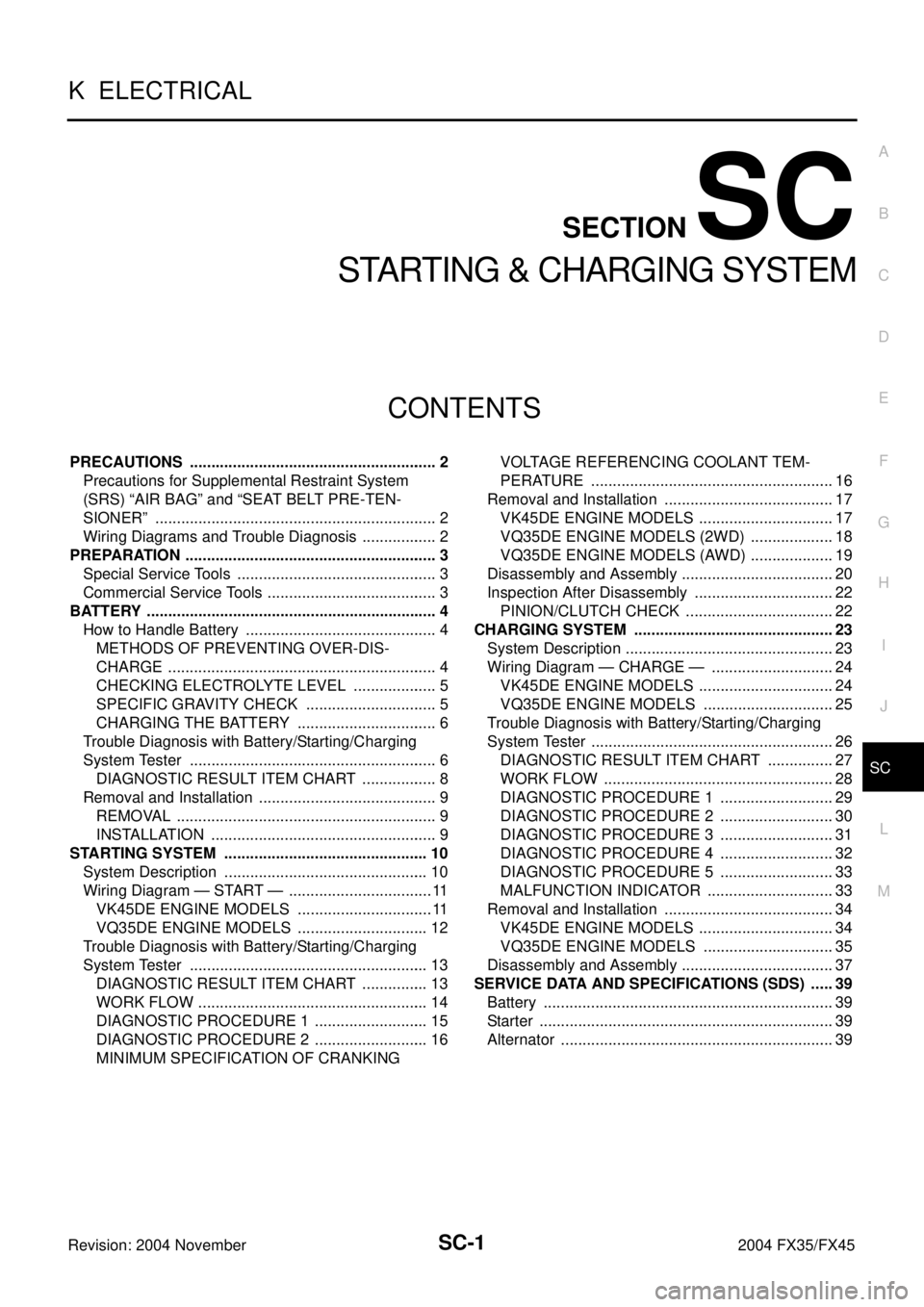
STARTING & CHARGING SYSTEM
K ELECTRICAL
CONTENTS
C
D
E
F
G
H
I
J
L
M
SECTION SC
A
B
SC
Revision: 2004 November 2004 FX35/FX45
STARTING & CHARGING SYSTEM
PRECAUTIONS .......................................................... 2
Precautions for Supplemental Restraint System
(SRS) “AIR BAG” and “SEAT BELT PRE-TEN-
SIONER” .................................................................. 2
Wiring Diagrams and Trouble Diagnosis .................. 2
PREPARATION ........................................................... 3
Special Service Tools ............................................... 3
Commercial Service Tools ........................................ 3
BATTERY .................................................................... 4
How to Handle Battery ............................................. 4
METHODS OF PREVENTING OVER-DIS-
CHARGE ............................................................... 4
CHECKING ELECTROLYTE LEVEL .................... 5
SPECIFIC GRAVITY CHECK ............................... 5
CHARGING THE BATTERY ................................. 6
Trouble Diagnosis with Battery/Starting/Charging
System Tester .......................................................... 6
DIAGNOSTIC RESULT ITEM CHART .................. 8
Removal and Installation .......................................... 9
REMOVAL ............................................................. 9
INSTALLATION ..................................................... 9
STARTING SYSTEM ................................................ 10
System Description ................................................ 10
Wiring Diagram — START — .................................. 11
VK45DE ENGINE MODELS ................................ 11
VQ35DE ENGINE MODELS ............................... 12
Trouble Diagnosis with Battery/Starting/Charging
System Tester ........................................................ 13
DIAGNOSTIC RESULT ITEM CHART ................ 13
WORK FLOW ...................................................... 14
DIAGNOSTIC PROCEDURE 1 ........................... 15
DIAGNOSTIC PROCEDURE 2 ........................... 16
MINIMUM SPECIFICATION OF CRANKING VOLTAGE REFERENCING COOLANT TEM-
PERATURE ......................................................... 16
Removal and Installation ........................................ 17
VK45DE ENGINE MODELS ................................ 17
VQ35DE ENGINE MODELS (2WD) .................... 18
VQ35DE ENGINE MODELS (AWD) .................... 19
Disassembly and Assembly .................................... 20
Inspection After Disassembly ................................. 22
PINION/CLUTCH CHECK ................................... 22
CHARGING SYSTEM ............................................... 23
System Description ................................................. 23
Wiring Diagram — CHARGE — ............................. 24
VK45DE ENGINE MODELS ................................ 24
VQ35DE ENGINE MODELS ............................... 25
Trouble Diagnosis with Battery/Starting/Charging
System Tester ......................................................... 26
DIAGNOSTIC RESULT ITEM CHART ................ 27
WORK FLOW ...................................................... 28
DIAGNOSTIC PROCEDURE 1 ........................... 29
DIAGNOSTIC PROCEDURE 2 ........................... 30
DIAGNOSTIC PROCEDURE 3 ........................... 31
DIAGNOSTIC PROCEDURE 4 ........................... 32
DIAGNOSTIC PROCEDURE 5 ........................... 33
MALFUNCTION INDICATOR .............................. 33
Removal and Installation ........................................ 34
VK45DE ENGINE MODELS ................................ 34
VQ35DE ENGINE MODELS ............................... 35
Disassembly and Assembly .................................... 37
SERVICE DATA AND SPECIFICATIONS (SDS) ...... 39
Battery .................................................................... 39
Starter ..................................................................... 39
Alternator ................................................................ 39
Page 4172 of 4449
AUTOMATIC DRIVE POSITIONER
SE-43
C
D
E
F
G
H
J
K
L
MA
B
SE
Revision: 2004 November 2004 FX35/FX45
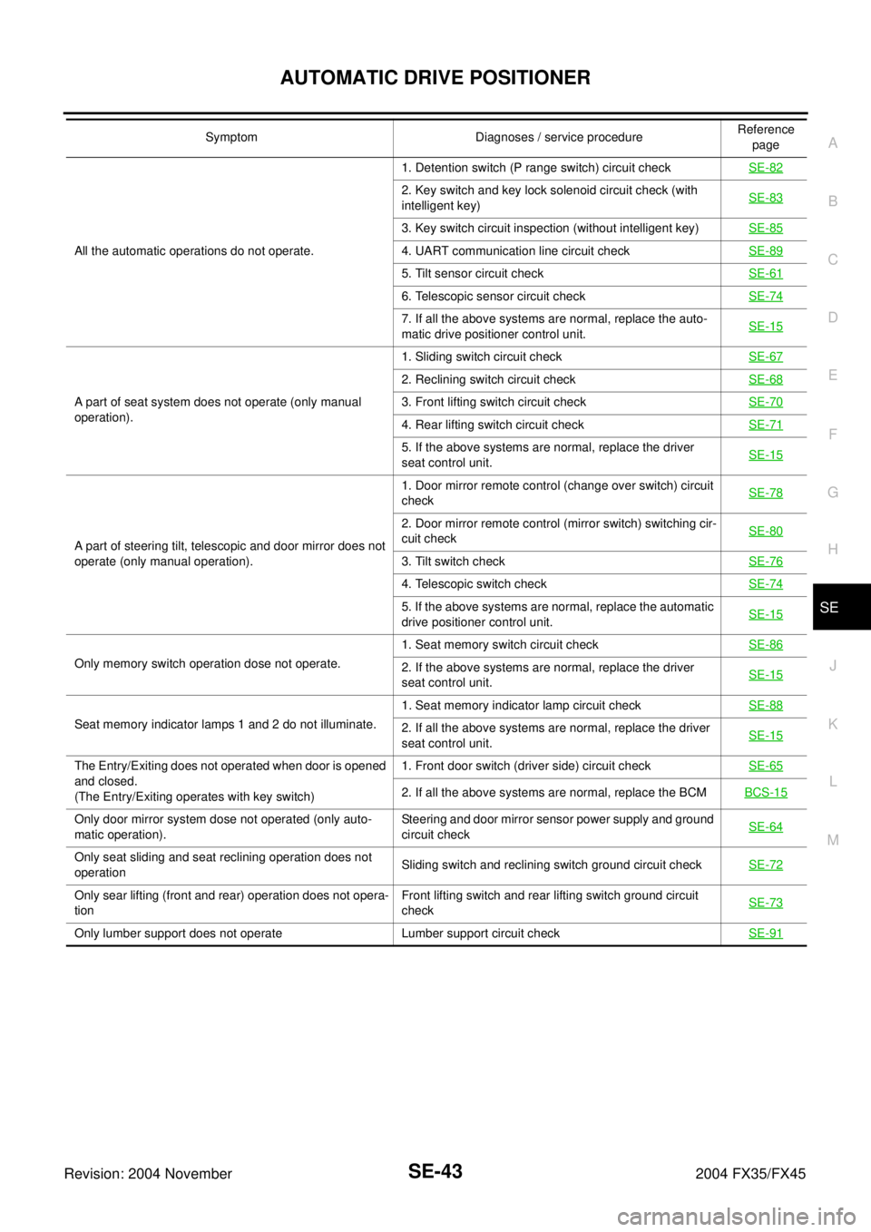
All the automatic operations do not operate.1. Detention switch (P range switch) circuit checkSE-82
2. Key switch and key lock solenoid circuit check (with
intelligent key)SE-83
3. Key switch circuit inspection (without intelligent key)SE-85
4. UART communication line circuit checkSE-89
5. Tilt sensor circuit checkSE-61
6. Telescopic sensor circuit checkSE-74
7. If all the above systems are normal, replace the auto-
matic drive positioner control unit.SE-15
A part of seat system does not operate (only manual
operation).1. Sliding switch circuit checkSE-67
2. Reclining switch circuit checkSE-68
3. Front lifting switch circuit checkSE-70
4. Rear lifting switch circuit checkSE-71
5. If the above systems are normal, replace the driver
seat control unit.SE-15
A part of steering tilt, telescopic and door mirror does not
operate (only manual operation).1. Door mirror remote control (change over switch) circuit
check SE-78
2. Door mirror remote control (mirror switch) switching cir-
cuit check SE-80
3. Tilt switch checkSE-76
4. Telescopic switch checkSE-74
5. If the above systems are normal, replace the automatic
drive positioner control unit.SE-15
Only memory switch operation dose not operate.1. Seat memory switch circuit checkSE-862. If the above systems are normal, replace the driver
seat control unit.SE-15
Seat memory indicator lamps 1 and 2 do not illuminate.1. Seat memory indicator lamp circuit checkSE-882. If all the above systems are normal, replace the driver
seat control unit.SE-15
The Entry/Exiting does not operated when door is opened
and closed.
(The Entry/Exiting operates with key switch)1. Front door switch (driver side) circuit checkSE-65
2. If all the above systems are normal, replace the BCMBCS-15
Only door mirror system dose not operated (only auto-
matic operation).Steering and door mirror sensor power supply and ground
circuit checkSE-64
Only seat sliding and seat reclining operation does not
operationSliding switch and reclining switch ground circuit checkSE-72
Only sear lifting (front and rear) operation does not opera-
tionFront lifting switch and rear lifting switch ground circuit
checkSE-73
Only lumber support does not operate Lumber support circuit checkSE-91
Symptom Diagnoses / service procedureReference
page
Page 4361 of 4449
WT-4
ROAD WHEEL
Revision: 2004 November 2004 FX35/FX45
ROAD WHEELPFP:40300
InspectionAES000OP
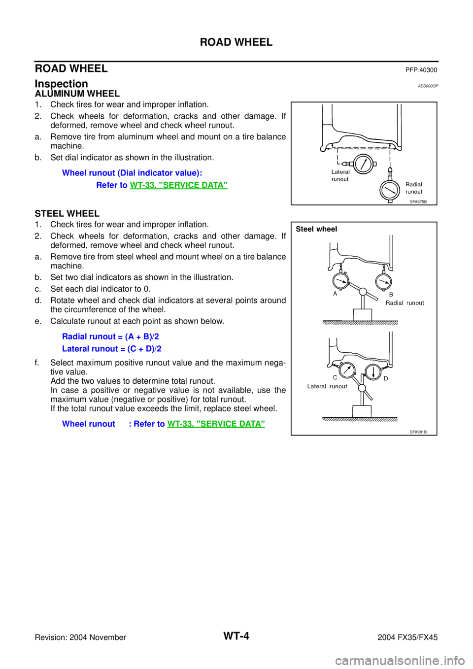
ALUMINUM WHEEL
1. Check tires for wear and improper inflation.
2. Check wheels for deformation, cracks and other damage. If
deformed, remove wheel and check wheel runout.
a. Remove tire from aluminum wheel and mount on a tire balance
machine.
b. Set dial indicator as shown in the illustration.
STEEL WHEEL
1. Check tires for wear and improper inflation.
2. Check wheels for deformation, cracks and other damage. If
deformed, remove wheel and check wheel runout.
a. Remove tire from steel wheel and mount wheel on a tire balance
machine.
b. Set two dial indicators as shown in the illustration.
c. Set each dial indicator to 0.
d. Rotate wheel and check dial indicators at several points around
the circumference of the wheel.
e. Calculate runout at each point as shown below.
f. Select maximum positive runout value and the maximum nega-
tive value.
Add the two values to determine total runout.
In case a positive or negative value is not available, use the
maximum value (negative or positive) for total runout.
If the total runout value exceeds the limit, replace steel wheel.Wheel runout (Dial indicator value):
Refer to WT-33, "
SERVICE DATA"
SFA975B
Radial runout = (A + B)/2
Lateral runout = (C + D)/2
Wheel runout : Refer to WT-33, "
SERVICE DATA"SFA981B