Page 2863 of 4449
EM-138
[VQ35DE]
CYLINDER BLOCK
Revision: 2004 November 2004 FX35/FX45
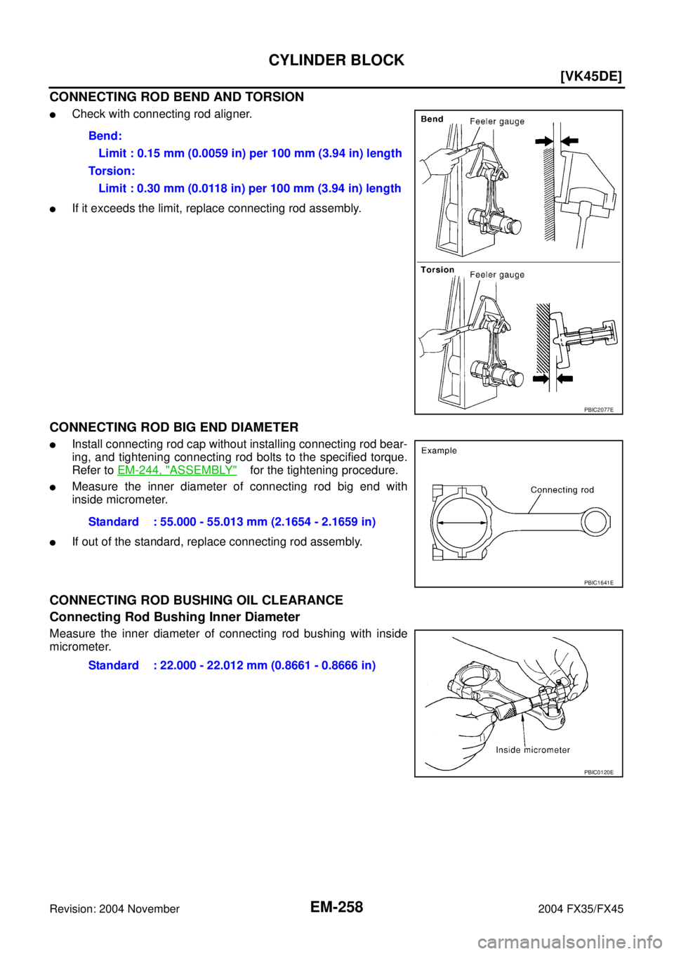
CONNECTING ROD BEND AND TORSION
�Check with connecting rod aligner.
�If it exceeds the limit, replace connecting rod assembly.
CONNECTING ROD BEARING HOUSING DIAMETER (BIG END)
Install connecting rod cap without connecting rod bearing installed.
After tightening connecting rod bolt to the specified torque, measure
the connecting rod big end inner diameter using an inside microme-
ter. Refer to EM-126, "
ASSEMBLY" for the tightening procedure.
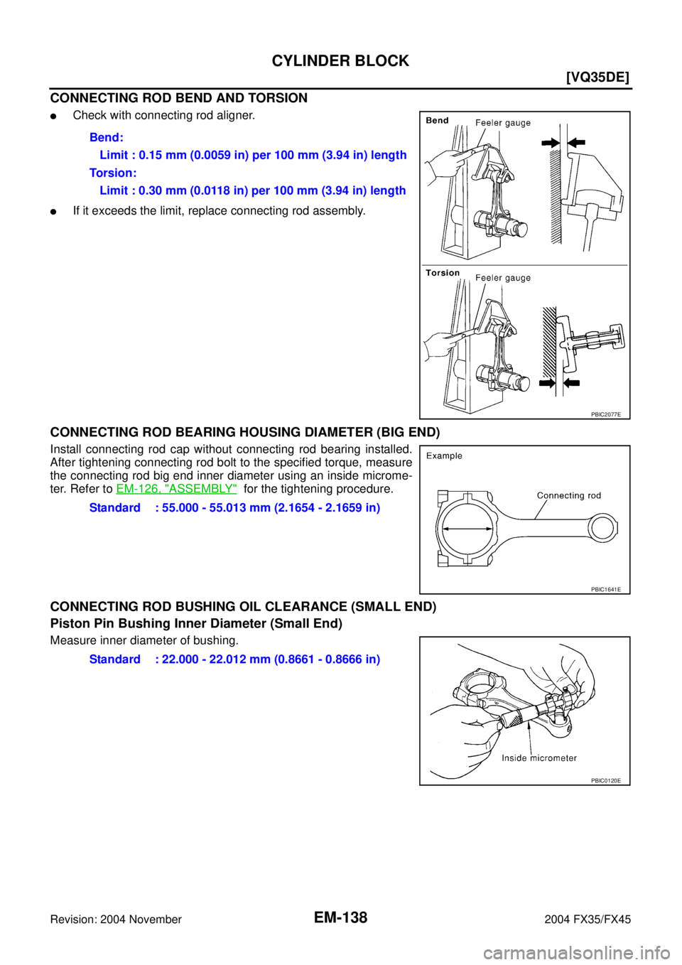
CONNECTING ROD BUSHING OIL CLEARANCE (SMALL END)
Piston Pin Bushing Inner Diameter (Small End)
Measure inner diameter of bushing.Bend:
Limit : 0.15 mm (0.0059 in) per 100 mm (3.94 in) length
Torsion:
Limit : 0.30 mm (0.0118 in) per 100 mm (3.94 in) length
PBIC2077E
Standard : 55.000 - 55.013 mm (2.1654 - 2.1659 in)
PBIC1641E
Standard : 22.000 - 22.012 mm (0.8661 - 0.8666 in)
PBIC0120E
Page 2875 of 4449
EM-150
[VQ35DE]
SERVICE DATA AND SPECIFICATIONS (SDS)
Revision: 2004 November 2004 FX35/FX45
CYLINDER HEAD
Unit: mm (in)
Valve Dimensions
Unit: mm (in) Items Standard Limit
Head surface distortion 0.03 (0.0012) 0.1 (0.004)
Normal cylinder head height “H” 126.3 - 126.5 (4.972 - 4.980)
PBIC0924E
Valve head diameter “D” Intake 37.0 - 37.3 (1.4567 - 1.4685)
Exhaust 31.2 - 31.5 (1.228 - 1.240)
Valve length “L”Intake 96.37 (3.7941)
Exhaust 93.90 (3.6968)
Valve stem diameter “d”Intake 5.965 - 5.980 (0.2348 - 0.2354)
Exhaust 5.955 - 5.970 (0.2344 - 0.2350)
Valve seat angle “α”Intake
45°15′ - 45°45′
Exhaust
Valve margin “T”Intake 1.1 (0.043)
Exhaust 1.3 (0.051)
Valve margin “T” limitMore than 0.5 (0.020)
Valve stem end surface grinding limit Less than 0.2 (0.008)
SEM188
Page 2876 of 4449
SERVICE DATA AND SPECIFICATIONS (SDS)
EM-151
[VQ35DE]
C
D
E
F
G
H
I
J
K
L
MA
EM
Revision: 2004 November 2004 FX35/FX45
Valve Guide
Unit: mm (in)
Items Standard 0.2 (0.008) Oversize (Service)
Valve guideOuter diameter 10.023 - 10.034 (0.3946 - 0.3950) 10.223 - 10.234 (0.4025 - 0.4029)
Inner diameter (Finished size) 6.000 - 6.018 (0.2362 - 0.2369) —
Cylinder head valve guide hole diameter 9.975 - 9.996 (0.3927 - 0.3935) 10.175 - 10.196 (0.4006 - 0.4014)
Interference fit of valve guide 0.027 - 0.059 (0.0011 - 0.0023)
Items Standard Limit
Stem to guide clearanceIntake 0.020 - 0.053 (0.0008 - 0.0021) 0.08 (0.0031)
Exhaust 0.030 - 0.063 (0.0012 - 0.0025) 0.09 (0.0035)
Projection length “L” 12.6 - 12.8 (0.496 - 0.504)
SEM950E
Page 2905 of 4449
![INFINITI FX35 2004 Service Manual EM-180
[VK45DE]
EXHAUST MANIFOLD AND THREE WAY CATALYST
Revision: 2004 November 2004 FX35/FX45
INSPECTION AFTER REMOVAL
Surface Distortion
�Check the surface distortion of the each exhaust manifold fl](/manual-img/42/57021/w960_57021-2904.png "INFINITI FX35 2004 Service Manual EM-180
[VK45DE]
EXHAUST MANIFOLD AND THREE WAY CATALYST
Revision: 2004 November 2004 FX35/FX45
INSPECTION AFTER REMOVAL
Surface Distortion
�Check the surface distortion of the each exhaust manifold fl")
EM-180
[VK45DE]
EXHAUST MANIFOLD AND THREE WAY CATALYST
Revision: 2004 November 2004 FX35/FX45
INSPECTION AFTER REMOVAL
Surface Distortion
�Check the surface distortion of the each exhaust manifold flange
mating surface with straightedge and feeler gauge.
�If it exceeds the limit, replace exhaust manifold.
INSTALLATION
Note the following, and install in the reverse order of removal.
Exhaust Manifold Gasket
Install exhaust manifold gasket with its directional protrusion set upward.
Refer to the figure of components on former page. Refer to EM-178, "
Removal and Installation" .
Exhaust Manifold
�Install exhaust manifold in numerical order as shown in the fig-
ure.
NOTE:
Tighten mounting nuts No. 1 to 4 in two steps. The numerical
order No. 9 to 12 shown second steps.
Heated Oxygen Sensor
�Install heated oxygen sensors in the original position.
�Install referring the following if the installation positions cannot
be identified.
*: The length of glass tube of bank 2 is longer than the one
of bank 1.
CAUTION:
�Before installing a new heated oxygen sensor, clean
exhaust system threads using oxygen sensor thread
cleaner (commercial service tool: J-43897-18 or J-43897-12), and apply anti-seize lubricant (com-
mercial service tool).
�Do not over torque heated oxygen sensor. Doing so may cause damage to the heated oxygen sen-
sor, resulting in “MIL” coming on.Limit : 0.3 mm (0.012 in)
PBIC1550E
PBIC1549E
Glass tube color
Heated oxygen sensor 1* : Black
Heated oxygen sensor 2 : White
PBIC2652E
Page 2983 of 4449
EM-258
[VK45DE]
CYLINDER BLOCK
Revision: 2004 November 2004 FX35/FX45
CONNECTING ROD BEND AND TORSION
�Check with connecting rod aligner.
�If it exceeds the limit, replace connecting rod assembly.
CONNECTING ROD BIG END DIAMETER
�Install connecting rod cap without installing connecting rod bear-
ing, and tightening connecting rod bolts to the specified torque.
Refer to EM-244, "
ASSEMBLY" for the tightening procedure.
�Measure the inner diameter of connecting rod big end with
inside micrometer.
�If out of the standard, replace connecting rod assembly.
CONNECTING ROD BUSHING OIL CLEARANCE
Connecting Rod Bushing Inner Diameter
Measure the inner diameter of connecting rod bushing with inside
micrometer.Bend:
Limit : 0.15 mm (0.0059 in) per 100 mm (3.94 in) length
Torsion:
Limit : 0.30 mm (0.0118 in) per 100 mm (3.94 in) length
PBIC2077E
Standard : 55.000 - 55.013 mm (2.1654 - 2.1659 in)
PBIC1641E
Standard : 22.000 - 22.012 mm (0.8661 - 0.8666 in)
PBIC0120E
Page 2995 of 4449
![INFINITI FX35 2004 Service Manual EM-270
[VK45DE]
SERVICE DATA AND SPECIFICATIONS (SDS)
Revision: 2004 November 2004 FX35/FX45
Valve Dimensions
Unit: mm (in)
Valve Guide
Unit: mm (in) Valve head diameter “D” Intake 36.0 - 36.3 (1.](/manual-img/42/57021/w960_57021-2994.png "INFINITI FX35 2004 Service Manual EM-270
[VK45DE]
SERVICE DATA AND SPECIFICATIONS (SDS)
Revision: 2004 November 2004 FX35/FX45
Valve Dimensions
Unit: mm (in)
Valve Guide
Unit: mm (in) Valve head diameter “D” Intake 36.0 - 36.3 (1.")
EM-270
[VK45DE]
SERVICE DATA AND SPECIFICATIONS (SDS)
Revision: 2004 November 2004 FX35/FX45
Valve Dimensions
Unit: mm (in)
Valve Guide
Unit: mm (in) Valve head diameter “D” Intake 36.0 - 36.3 (1.417 - 1.429)
Exhaust 31.2 - 31.5 (1.228 - 1.240)
Valve length “L”Intake 96.57 (3.8020)
Exhaust 94.50 (3.720)
Valve stem diameter “d”Intake 5.972 - 5.980 (0.2351 - 0.2354)
Exhaust 5.962 - 5.970 (0.2347 - 0.2350)
Valve seat angle “α”Intake
45°15′ - 45°45′
Exhaust
Valve margin “T”Intake 1.15 - 1.45 (0.0453 - 0.0571)
Exhaust 1.85 - 2.15 (0.0728 - 0.0846)
SEM188
ItemsStandard 0.2 (0.008) Oversize (Service)
Valve guideOuter diameter10.023 - 10.034 (0.3946 -
0.3950)10.223 - 10.234 (0.4025 -
0.4029)
Inner diameter (Finished size) 6.000 - 6.018 (0.2362 - 0.2369)
Cylinder head valve guide hole diameter 9.975 - 9.996 (0.3927 - 0.3935)10.175 - 10.196 (0.4006 -
0.4014)
Interference fit of valve guide 0.027 - 0.059 (0.0011 - 0.0023)
ItemsStandard Limit
Valve guide clearanceIntake 0.020 - 0.046 (0.0008 - 0.0018) 0.08 (0.003)
Exhaust 0.030 - 0.056 (0.0012 - 0.0022) 0.1 (0.004)
Projection length “L”Intake 10.1 - 10.3 (0.398 - 0.406) —
Exhaust 10.0 - 10.4 (0.394 - 0.409) —
PBIC0184E
Page 3026 of 4449
![INFINITI FX35 2004 Service Manual FRONT DRIVE SHAFT
FAX-17
[AWD]
C
E
F
G
H
I
J
K
L
MA
B
FA X
Revision: 2004 November 2004 FX35/FX45
7. Install housing to spider assembly. Apply Nissan genuine grease
or equivalent to housing.
8. Instal](/manual-img/42/57021/w960_57021-3025.png "INFINITI FX35 2004 Service Manual FRONT DRIVE SHAFT
FAX-17
[AWD]
C
E
F
G
H
I
J
K
L
MA
B
FA X
Revision: 2004 November 2004 FX35/FX45
7. Install housing to spider assembly. Apply Nissan genuine grease
or equivalent to housing.
8. Instal")
FRONT DRIVE SHAFT
FAX-17
[AWD]
C
E
F
G
H
I
J
K
L
MA
B
FA X
Revision: 2004 November 2004 FX35/FX45
7. Install housing to spider assembly. Apply Nissan genuine grease
or equivalent to housing.
8. Install boot securely into grooves (indicated by * marks) shown
in the figure.
CAUTION:
If there is grease on boot mounting surfaces (indicated by*
marks) of shaft and housing, boot may come off. Remove
all grease from surfaces.
9. Make sure boot installation length “L” is the length indicated
below. Insert a flat-bladed screwdriver or similar tool into smaller
side of boot. Bleed air from boot to prevent boot deformation.
CAUTION:
�Boot may break if boot installation length is less than standard value.
�Take care not to touch the tip of screwdriver to inside surface of boot.
10. Install new larger and smaller boot bands securely with a suit-
able tool.
NOTE:
�Discard old boot bands; replace with new ones.
�Secure boot band so that dimension “M” shown bellow right
satisfies the following:
11. After installing housing and shaft, rotate boot to check whether
or not the actual position is correct. If boot position is not correct,
secure boot with new boot bands again.Grease amount : 95 − 105 g (3.35 − 3.70 oz)
SDIA1445E
Boot installation Length “L ”:
95 − 97 mm (3.74 − 3.82 in)SDIA1126E
RAC1133D
Large diameter side : 3.0 mm (0.118 in)
Small diameter side : 2.0 mm (0.079 in)
DSF0047D
Page 3027 of 4449
![INFINITI FX35 2004 Service Manual FAX-18
[AWD]
FRONT DRIVE SHAFT
Revision: 2004 November 2004 FX35/FX45
Wheel Side
1. Insert the amount grease (Nissan genuine grease or equivalent)
into joint sub-assembly serration hole until grease b](/manual-img/42/57021/w960_57021-3026.png "INFINITI FX35 2004 Service Manual FAX-18
[AWD]
FRONT DRIVE SHAFT
Revision: 2004 November 2004 FX35/FX45
Wheel Side
1. Insert the amount grease (Nissan genuine grease or equivalent)
into joint sub-assembly serration hole until grease b")
FAX-18
[AWD]
FRONT DRIVE SHAFT
Revision: 2004 November 2004 FX35/FX45
Wheel Side
1. Insert the amount grease (Nissan genuine grease or equivalent)
into joint sub-assembly serration hole until grease begins to
ooze from ball groove and serration hole. After inserting grease,
use a shop cloth to wipe off old grease that has oozed out.
2. Wind serrated part of shaft with tape. Install boot band and boot
to shaft. Be careful not to damage boot.
NOTE:
Discard old boot band and boot; replace with new ones.
3. Remove protective tape wound around serrated part of shaft.
4. Attach circular clip to shaft. At this time, circular clip must fit
securely into shaft groove. Attach nut to joint sub-assembly.
Use a wooden hammer to press-fit.
NOTE:
Discard old circular clip; replace with new one.
5. Insert the specified amount of grease (Nissan genuine grease or
equivalent) listed below into boot from large end of boot.
6. Install boot securely into grooves (indicated by * marks) shown
in the figure.
CAUTION:
If there is grease on boot mounting surfaces (indicated by*
marks) of shaft and housing of joint sub assembly, boot
may come off. Remove all grease from surfaces.
7. Make sure boot installation length “L” is the length indicated
below. Insert a flat-bladed screwdriver or similar tool into smaller
side of boot. Bleed air from boot to prevent boot deformation.
CAUTION:
�Boot may brake if boot installation length is less than standard value.
�Be careful that screwdriver tip does not contact inside surface of boot.
SDIA1127E
SFA800
Grease amount : 95 − 11 5 g ( 3 . 3 5 − 4.06 oz)
RAC0049D
Boot installation length “L” : 136 mm (5.35 in)SDIA1736E
![INFINITI FX35 2004 Service Manual EM-150
[VQ35DE]
SERVICE DATA AND SPECIFICATIONS (SDS)
Revision: 2004 November 2004 FX35/FX45
CYLINDER HEAD
Unit: mm (in)
Valve Dimensions
Unit: mm (in) Items Standard Limit
Head surface distortion 0.0](/manual-img/42/57021/w960_57021-2874.png "INFINITI FX35 2004 Service Manual EM-150
[VQ35DE]
SERVICE DATA AND SPECIFICATIONS (SDS)
Revision: 2004 November 2004 FX35/FX45
CYLINDER HEAD
Unit: mm (in)
Valve Dimensions
Unit: mm (in) Items Standard Limit
Head surface distortion 0.0")
![INFINITI FX35 2004 Service Manual SERVICE DATA AND SPECIFICATIONS (SDS)
EM-151
[VQ35DE]
C
D
E
F
G
H
I
J
K
L
MA
EM
Revision: 2004 November 2004 FX35/FX45
Valve Guide
Unit: mm (in)
Items Standard 0.2 (0.008) Oversize (Service)
Valve gui](/manual-img/42/57021/w960_57021-2875.png "INFINITI FX35 2004 Service Manual SERVICE DATA AND SPECIFICATIONS (SDS)
EM-151
[VQ35DE]
C
D
E
F
G
H
I
J
K
L
MA
EM
Revision: 2004 November 2004 FX35/FX45
Valve Guide
Unit: mm (in)
Items Standard 0.2 (0.008) Oversize (Service)
Valve gui")