2004 INFINITI FX35 engine spec
[x] Cancel search: engine specPage 155 of 4449

AT-78
TROUBLE DIAGNOSIS
Revision: 2004 November 2004 FX35/FX45
34
Slips/Will
Not
EngageWhen you press the
accelerator pedal and
shift speed D2 → D1
or M
2 → M1 the
engine idles or the
transmission slips.ON vehicle1. Fluid level and stateAT- 5 1
2. Vehicle speed sensor A/T and vehicle speed sensor MTRAT- 11 6,
AT- 1 4 5
3. ATF pressure switch 5 and direct clutch solenoid valveAT- 1 8 2,
AT- 1 6 0
4. CAN communication lineAT- 1 0 5
5. Line pressure testAT- 5 2
6. Control valve with TCMAT- 2 4 2
OFF vehicle7. Torque converterAT- 2 8 6
8. Oil pump assemblyAT- 3 0 3
9. 3rd one-way clutchAT- 3 0 6
10. 1st one-way clutchAT- 3 1 4
11. Gear systemAT- 2 7 4
12. Reverse brakeAT- 2 8 6
13. Forward one-way clutch (Parts behind drum support is
impossible to perform inspection by disassembly. Refer to
AT-17, "
Cross-Sectional View (2WD Models)" or AT-18,
"Cross-Sectional View (AWD Models)" )AT- 2 8 6
14. Forward brake (Parts behind drum support is impossible
to perform inspection by disassembly. Refer to AT-17,
"Cross-Sectional View (2WD Models)" or AT- 1 8 , "Cross-
Sectional View (AWD Models)" )AT- 2 8 6
35With selector lever in
D position, accelera-
tion is extremely poor.ON vehicle1. Fluid level and stateAT- 5 1
2. Line pressure testAT- 5 2
3. Accelerator pedal position sensorAT- 1 3 6
4. CAN communication lineAT- 1 0 5
5. PNP switchAT- 11 2
6. Control linkage adjustmentAT- 2 3 4
7. Control valve with TCMAT- 2 4 2
OFF vehicle8. Torque converterAT- 2 8 6
9. Oil pump assemblyAT- 3 0 3
10. 1st one-way clutchAT- 3 1 4
11. Gear systemAT- 2 7 4
12. Reverse brakeAT- 2 8 6
13. Forward one-way clutch (Parts behind drum support is
impossible to perform inspection by disassembly. Refer to
AT-17, "
Cross-Sectional View (2WD Models)" or AT-18,
"Cross-Sectional View (AWD Models)" )AT- 2 8 6
14. Forward brake (Parts behind drum support is impossible
to perform inspection by disassembly. Refer to AT-17,
"Cross-Sectional View (2WD Models)" or AT- 1 8 , "Cross-
Sectional View (AWD Models)" )AT- 2 8 6
No. Items Symptom Condition Diagnostic ItemReference
page
Page 156 of 4449

TROUBLE DIAGNOSIS
AT-79
D
E
F
G
H
I
J
K
L
MA
B
AT
Revision: 2004 November 2004 FX35/FX45
36
Slips/Will
Not
EngageWith selector lever in
R position, accelera-
tion is extremely poor.ON vehicle1. Fluid level and stateAT- 5 1
2. Line pressure testAT- 5 2
3. Accelerator pedal position sensorAT-136
4. ATF pressure switch 6, high and low reverse clutch sole-
noid valveAT-184,
AT-164
5. CAN communication lineAT-105
6. PNP switchAT- 11 2
7. Control linkage adjustmentAT-234
8. Control valve with TCMAT-242
OFF vehicle9. Gear systemAT-27410. Output shaft AT-286
11. Reverse brakeAT-286
37While starting off by
accelerating in 1st,
engine races or slip-
page occurs.ON vehicle1. Fluid level and stateAT- 5 1
2. Line pressure testAT- 5 2
3. Accelerator pedal position sensorAT-136
4. CAN communication lineAT-105
5. Control valve with TCMAT-242
OFF vehicle6. Torque converterAT-286
7. Oil pump assemblyAT-303
8. 3rd one-way clutchAT-306
9. 1st one-way clutchAT-314
10. Gear systemAT-274
11. Reverse brakeAT-286
12. Forward one-way clutch (Parts behind drum support is
impossible to perform inspection by disassembly. Refer to
AT- 1 7 , "
Cross-Sectional View (2WD Models)" or AT- 1 8 ,
"Cross-Sectional View (AWD Models)" )AT-286
13. Forward brake (Parts behind drum support is impossible
to perform inspection by disassembly. Refer to AT-17,
"Cross-Sectional View (2WD Models)" or AT-18, "Cross-
Sectional View (AWD Models)" )AT-286
No. Items Symptom Condition Diagnostic ItemReference
page
Page 157 of 4449

AT-80
TROUBLE DIAGNOSIS
Revision: 2004 November 2004 FX35/FX45
38
Slips/Will
Not
EngageWhile accelerating in
2nd, engine races or
slippage occurs.ON vehicle1. Fluid level and stateAT- 5 1
2. Line pressure testAT- 5 2
3. Accelerator pedal position sensorAT- 1 3 6
4. CAN communication lineAT- 1 0 5
5. ATF pressure switch 5 and direct clutch solenoid valveAT- 1 8 2,
AT- 1 6 0
6. Control valve with TCMAT- 2 4 2
OFF vehicle7. Torque converterAT- 2 8 6
8. Oil pump assemblyAT- 3 0 3
9. 3rd one-way clutchAT- 3 0 6
10. Gear systemAT- 2 7 4
11. Direct clutchAT- 3 2 3
12. Forward brake (Parts behind drum support is impossible
to perform inspection by disassembly. Refer to AT-17,
"Cross-Sectional View (2WD Models)" or AT- 1 8 , "Cross-
Sectional View (AWD Models)" )AT- 2 8 6
39While accelerating in
3rd, engine races or
slippage occurs.ON vehicle1. Fluid level and stateAT- 5 1
2. Line pressure testAT- 5 2
3. Accelerator pedal position sensorAT- 1 3 6
4. CAN communication lineAT- 1 0 5
5. ATF pressure switch 6, high and low reverse clutch sole-
noid valveAT- 1 8 4,
AT- 1 6 4
6. Control valve with TCMAT- 2 4 2
OFF vehicle7. Torque converterAT- 2 8 6
8. Oil pump assemblyAT- 3 0 3
9. 3rd one-way clutchAT- 3 0 6
10. Gear systemAT- 2 7 4
11. High and low reverse clutchAT- 3 2 0
12. Forward one-way clutch (Parts behind drum support is
impossible to perform inspection by disassembly. Refer to
AT-17, "
Cross-Sectional View (2WD Models)" or AT-18,
"Cross-Sectional View (AWD Models)" )AT- 2 8 6
13. Forward brake (Parts behind drum support is impossible
to perform inspection by disassembly. Refer to AT-17,
"Cross-Sectional View (2WD Models)" or AT- 1 8 , "Cross-
Sectional View (AWD Models)" )AT- 2 8 6
No. Items Symptom Condition Diagnostic ItemReference
page
Page 163 of 4449

AT-86
TROUBLE DIAGNOSIS
Revision: 2004 November 2004 FX35/FX45
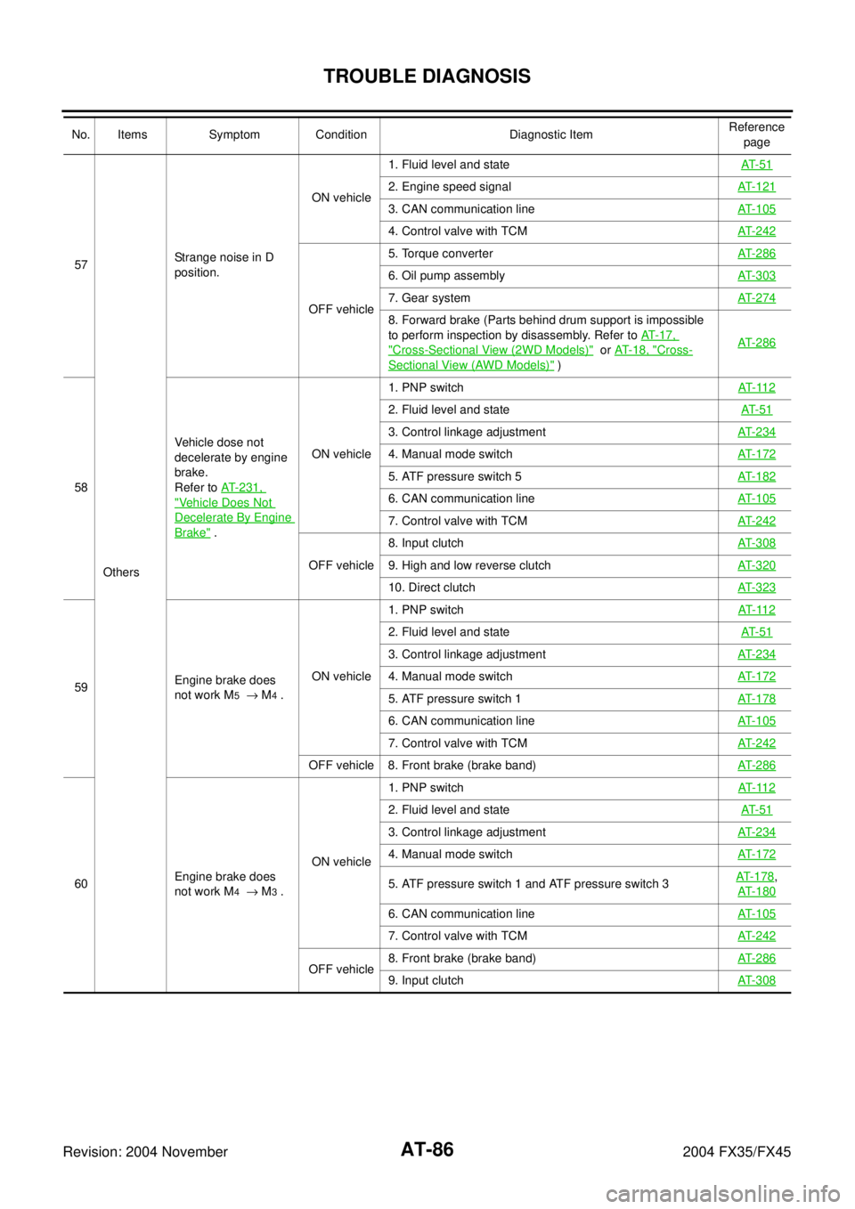
57
OthersStrange noise in D
position.ON vehicle1. Fluid level and stateAT- 5 1
2. Engine speed signalAT- 1 2 1
3. CAN communication lineAT- 1 0 5
4. Control valve with TCMAT- 2 4 2
OFF vehicle5. Torque converterAT- 2 8 6
6. Oil pump assemblyAT- 3 0 3
7. Gear systemAT- 2 7 4
8. Forward brake (Parts behind drum support is impossible
to perform inspection by disassembly. Refer to AT-17,
"Cross-Sectional View (2WD Models)" or AT- 1 8 , "Cross-
Sectional View (AWD Models)" )AT- 2 8 6
58Vehicle dose not
decelerate by engine
brake.
Refer to AT-231,
"Vehicle Does Not
Decelerate By Engine
Brake" .ON vehicle1. PNP switchAT- 11 2
2. Fluid level and stateAT- 5 1
3. Control linkage adjustmentAT- 2 3 4
4. Manual mode switchAT- 1 7 2
5. ATF pressure switch 5AT- 1 8 2
6. CAN communication lineAT- 1 0 5
7. Control valve with TCMAT- 2 4 2
OFF vehicle8. Input clutchAT- 3 0 89. High and low reverse clutchAT- 3 2 0
10. Direct clutchAT- 3 2 3
59Engine brake does
not work M5 → M4 .ON vehicle1. PNP switchAT- 11 2
2. Fluid level and stateAT- 5 1
3. Control linkage adjustmentAT- 2 3 4
4. Manual mode switchAT- 1 7 2
5. ATF pressure switch 1AT- 1 7 8
6. CAN communication lineAT- 1 0 5
7. Control valve with TCMAT- 2 4 2
OFF vehicle 8. Front brake (brake band) AT- 2 8 6
60Engine brake does
not work M4 → M3 .ON vehicle1. PNP switchAT- 11 2
2. Fluid level and stateAT- 5 1
3. Control linkage adjustmentAT- 2 3 4
4. Manual mode switchAT- 1 7 2
5. ATF pressure switch 1 and ATF pressure switch 3AT- 1 7 8,
AT- 1 8 0
6. CAN communication lineAT- 1 0 5
7. Control valve with TCMAT- 2 4 2
OFF vehicle8. Front brake (brake band)AT- 2 8 69. Input clutchAT- 3 0 8
No. Items Symptom Condition Diagnostic ItemReference
page
Page 164 of 4449

TROUBLE DIAGNOSIS
AT-87
D
E
F
G
H
I
J
K
L
MA
B
AT
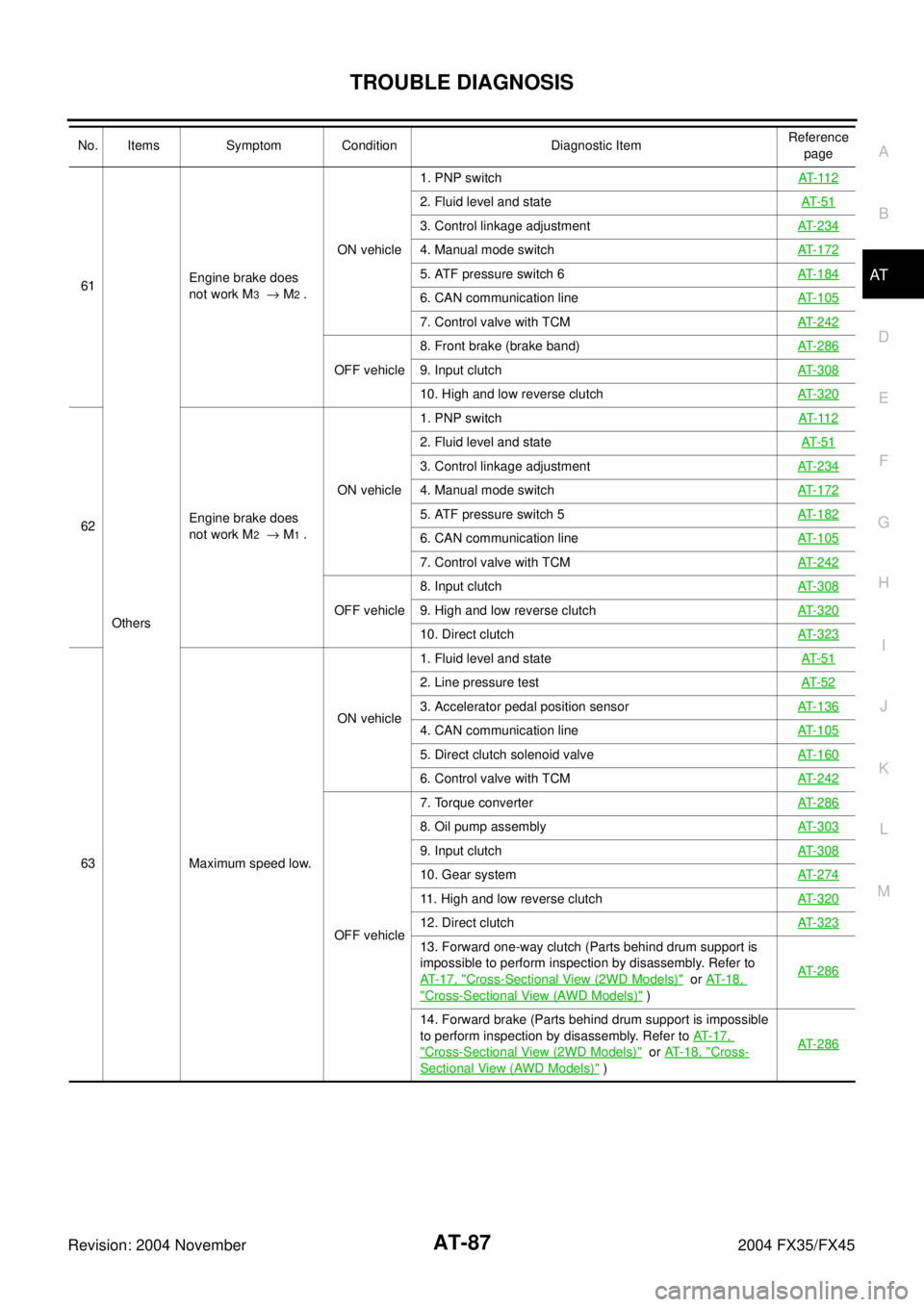
Revision: 2004 November 2004 FX35/FX4561
OthersEngine brake does
not work M3 → M2 .ON vehicle1. PNP switchAT- 11 2
2. Fluid level and stateAT- 5 1
3. Control linkage adjustmentAT-234
4. Manual mode switchAT-172
5. ATF pressure switch 6AT-184
6. CAN communication lineAT-105
7. Control valve with TCMAT-242
OFF vehicle8. Front brake (brake band)AT-2869. Input clutchAT-308
10. High and low reverse clutchAT-320
62Engine brake does
not work M2 → M1 .ON vehicle1. PNP switchAT- 11 2
2. Fluid level and stateAT- 5 1
3. Control linkage adjustmentAT-234
4. Manual mode switchAT-172
5. ATF pressure switch 5AT-182
6. CAN communication lineAT-105
7. Control valve with TCMAT-242
OFF vehicle8. Input clutchAT-3089. High and low reverse clutchAT-320
10. Direct clutchAT-323
63 Maximum speed low.ON vehicle1. Fluid level and stateAT- 5 1
2. Line pressure testAT- 5 2
3. Accelerator pedal position sensorAT-136
4. CAN communication lineAT-105
5. Direct clutch solenoid valveAT-160
6. Control valve with TCMAT-242
OFF vehicle7. Torque converter AT-286
8. Oil pump assemblyAT-303
9. Input clutchAT-308
10. Gear systemAT-274
11. High and low reverse clutchAT-320
12. Direct clutchAT-323
13. Forward one-way clutch (Parts behind drum support is
impossible to perform inspection by disassembly. Refer to
AT- 1 7 , "
Cross-Sectional View (2WD Models)" or AT- 1 8 ,
"Cross-Sectional View (AWD Models)" )AT-286
14. Forward brake (Parts behind drum support is impossible
to perform inspection by disassembly. Refer to AT-17,
"Cross-Sectional View (2WD Models)" or AT-18, "Cross-
Sectional View (AWD Models)" )AT-286
No. Items Symptom Condition Diagnostic ItemReference
page
Page 165 of 4449

AT-88
TROUBLE DIAGNOSIS
Revision: 2004 November 2004 FX35/FX45
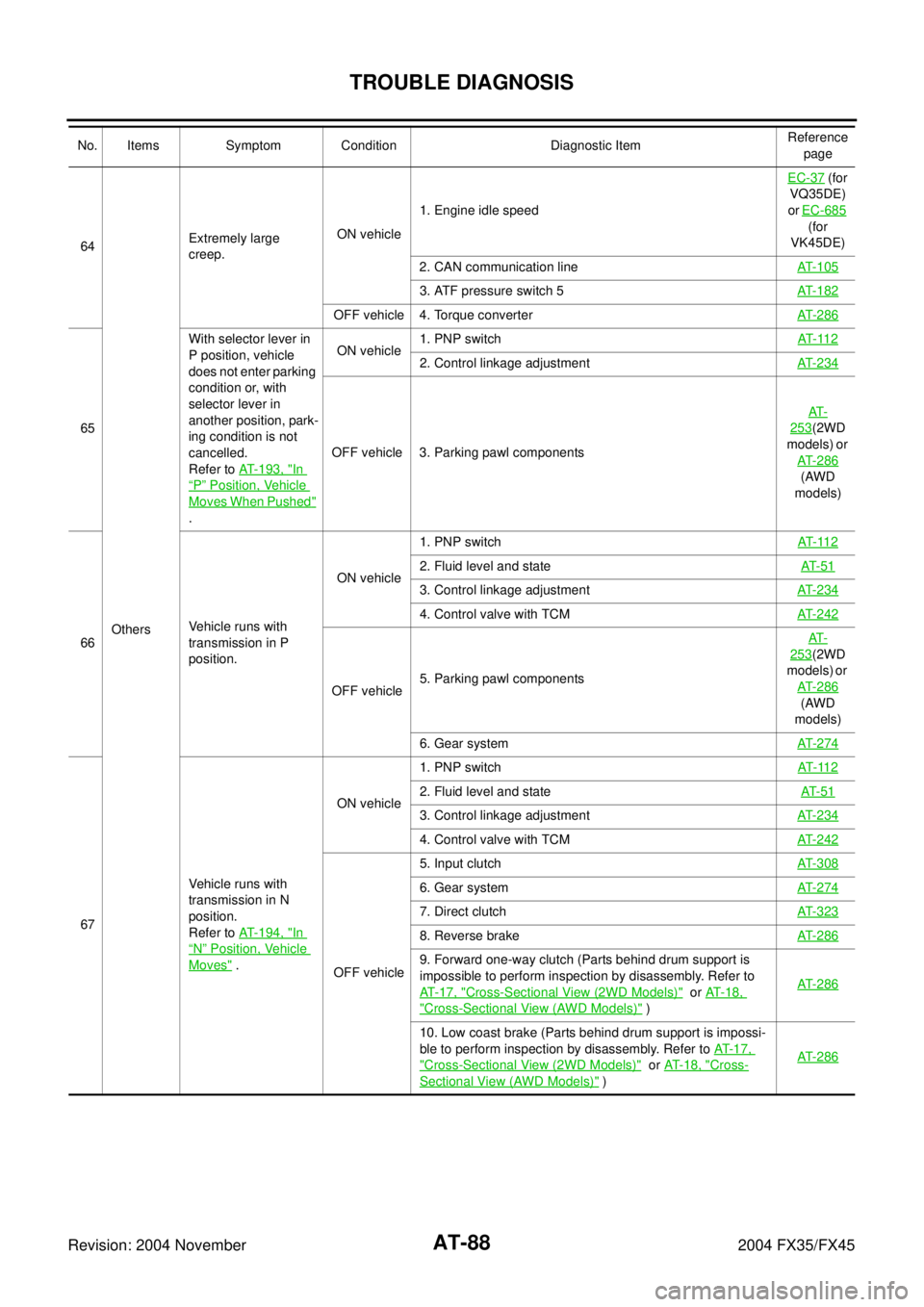
64
OthersExtremely large
creep.ON vehicle1. Engine idle speed EC-37
(for
VQ35DE)
or EC-685
(for
VK45DE)
2. CAN communication lineAT- 1 0 5
3. ATF pressure switch 5AT- 1 8 2
OFF vehicle 4. Torque converterAT- 2 8 6
65With selector lever in
P position, vehicle
does not enter parking
condition or, with
selector lever in
another position, park-
ing condition is not
cancelled.
Refer to AT-193, "
In
“P” Position, Vehicle
Moves When Pushed"
.ON vehicle1. PNP switchAT- 11 2
2. Control linkage adjustmentAT- 2 3 4
OFF vehicle 3. Parking pawl componentsAT-
253(2WD
models) or
AT- 2 8 6
(AWD
models)
66Vehicle runs with
transmission in P
position.ON vehicle1. PNP switchAT- 11 2
2. Fluid level and stateAT- 5 1
3. Control linkage adjustmentAT- 2 3 4
4. Control valve with TCMAT- 2 4 2
OFF vehicle5. Parking pawl componentsAT-
253(2WD
models) or
AT- 2 8 6
(AWD
models)
6. Gear systemAT- 2 7 4
67Vehicle runs with
transmission in N
position.
Refer to AT-194, "In
“N” Position, Vehicle
Moves" .ON vehicle1. PNP switchAT- 11 2
2. Fluid level and stateAT- 5 1
3. Control linkage adjustmentAT- 2 3 4
4. Control valve with TCMAT- 2 4 2
OFF vehicle5. Input clutchAT- 3 0 8
6. Gear systemAT- 2 7 4
7. Direct clutchAT- 3 2 3
8. Reverse brakeAT- 2 8 6
9. Forward one-way clutch (Parts behind drum support is
impossible to perform inspection by disassembly. Refer to
AT-17, "
Cross-Sectional View (2WD Models)" or AT-18,
"Cross-Sectional View (AWD Models)" )AT- 2 8 6
10. Low coast brake (Parts behind drum support is impossi-
ble to perform inspection by disassembly. Refer to AT- 1 7 ,
"Cross-Sectional View (2WD Models)" or AT- 1 8 , "Cross-
Sectional View (AWD Models)" )AT- 2 8 6
No. Items Symptom Condition Diagnostic ItemReference
page
Page 175 of 4449

AT-98
TROUBLE DIAGNOSIS
Revision: 2004 November 2004 FX35/FX45
GEAR — X XGear position recognized by the TCM updated
after gear-shifting
ENGINE SPEED (rpm) X X X
TURBINE REV (rpm) X X X
OUTPUT REV (rpm) X X X
GEAR RATIO — X X
TC SLIP SPEED (rpm) — X XDifference between engine speed and torque
converter input shaft speed
F SUN GR REV (rpm) — — X
F CARR GR REV (rpm) — — X
ATF TEMP SE 1 (V) X — X
ATF TEMP SE 2 (V) X — X
ATF TEMP 1 (°C) — X X
ATF TEMP 2 (°C) — X X
BATTERY VOLT (V) X — X
ATF PRES SW 1 (ON-OFF display) X X X (for FR/B solenoid)
ATF PRES SW 2 (ON-OFF display) X X X (for LC/B solenoid)
ATF PRES SW 3 (ON-OFF display) X X X (for I/C solenoid)
ATF PRES SW 5 (ON-OFF display) X X X (for D/C solenoid)
ATF PRES SW 6 (ON-OFF display) X X X (for HLR/C solenoid)
PNP SW 1 (ON-OFF display) X — X
PNP SW 2 (ON-OFF display) X — X
PNP SW 3 (ON-OFF display) X — X
PNP SW 4 (ON-OFF display) X — X
1 POSITION SW (ON-OFF display) X — X
SLCT LVR POSI — X XSelector lever position is recognized by the
TCM.
For fail-safe operation, the specific value used
for control is displayed.
OD CONT SW (ON-OFF display) X — X
Not mounted but displayed. POWERSHIFT SW (ON-OFF display) X — X
HOLD SW (ON-OFF display) X — X
MANU MODE SW (ON-OFF display) X — X
NON M-MODE SW (ON-OFF display) X — X
UP SW LEVER (ON-OFF display) X — X
DOWN SW LEVER (ON-OFF display) X — X
SFT UP ST SW (ON-OFF display) — — X
Not mounted but displayed.
SFT DWN ST SW (ON-OFF display) — — X
ASCD·OD CUT (ON-OFF display) — — X
ASCD·CRUISE (ON-OFF display) — — X
ABS SIGNAL (ON-OFF display) — — X
ACC OD CUT (ON-OFF display) — — X
ICC (intelligent cruise control)
ACC SIGNAL (ON-OFF display) — — XMonitored item (Unit)Monitor Item Selection
Remarks ECU
INPUT
SIGNALSMAIN SIG-
NALSSELEC-
TION
FROM
MENU
Page 184 of 4449

DTC U1000 CAN COMMUNICATION LINE
AT-107
D
E
F
G
H
I
J
K
L
MA
B
AT
Revision: 2004 November 2004 FX35/FX45
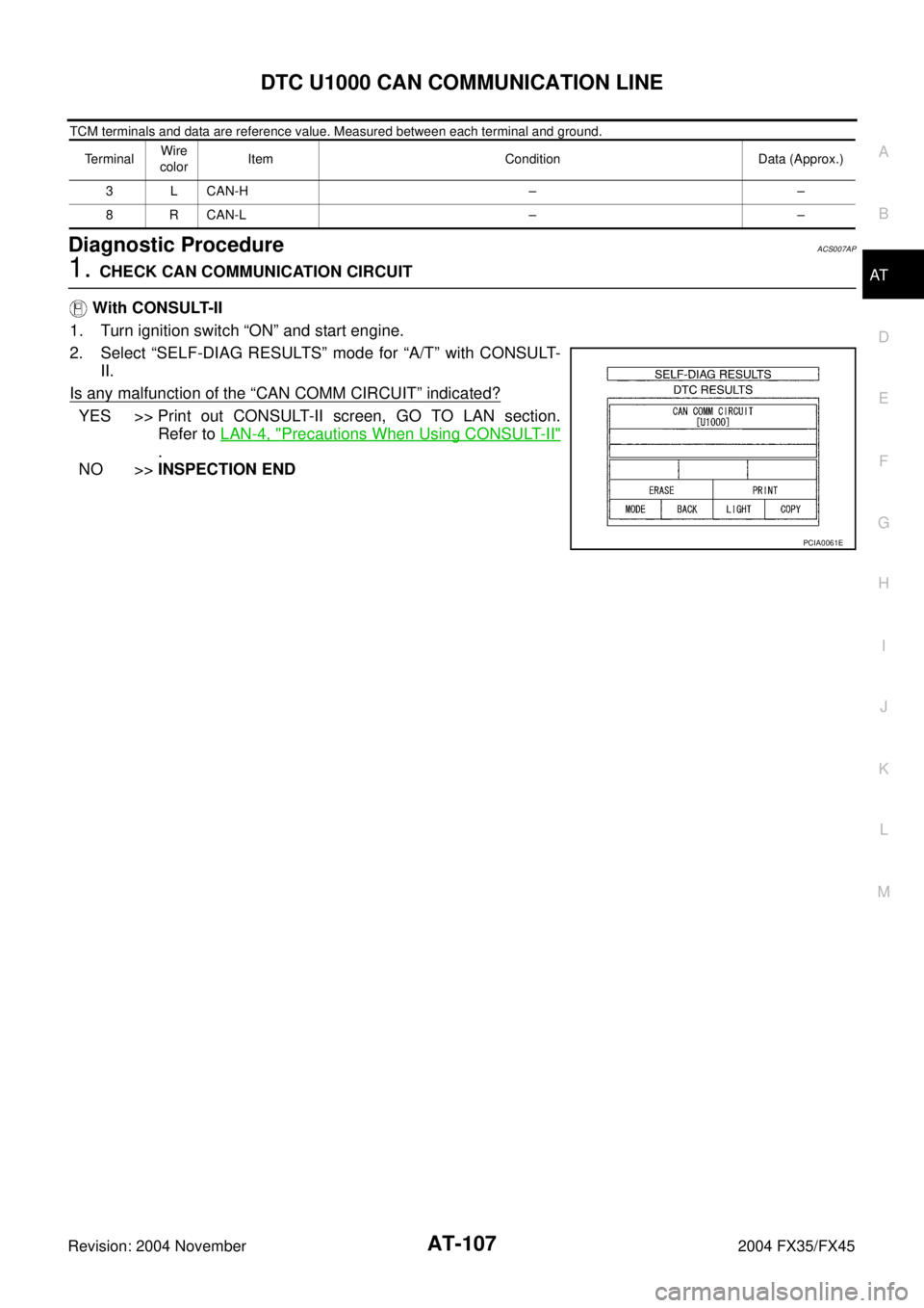
TCM terminals and data are reference value. Measured between each terminal and ground.
Diagnostic ProcedureACS007AP
1. CHECK CAN COMMUNICATION CIRCUIT
With CONSULT-II
1. Turn ignition switch “ON” and start engine.
2. Select “SELF-DIAG RESULTS” mode for “A/T” with CONSULT-
II.
Is any malfunction of the
“CAN COMM CIRCUIT” indicated?
YES >> Print out CONSULT-II screen, GO TO LAN section.
Refer to LAN-4, "
Precautions When Using CONSULT-II"
.
NO >>INSPECTION END
TerminalWire
colorItem Condition Data (Approx.)
3 L CAN-H – –
8 R CAN-L – –
PCIA0061E