Page 3030 of 4449
FRONT DRIVE SHAFT
FAX-21
[AWD]
C
E
F
G
H
I
J
K
L
MA
B
FA X
Revision: 2004 November 2004 FX35/FX45
NOTE:
Housing and spider assembly are components which are used as a set.
ASSEMBLY
Front Final Drive Assembly Side
1. Wind serrated part of drive shaft with tape. Install boot band and
boot to shaft. Be careful not to damage boot.
NOTE:
Discard old boot band and boot; replace with each new one.
2. Remove protective tape wound around serrated part of shaft.
3. Line up alignment marks which were made when spider assem-
bly was removed. Install spider assembly, with serration chamfer
facing dive shaft.
4. Secure spider assembly with snap ring.
NOTE:
Discard old snap ring; replace with new one.
5. Apply Nissan genuine grease or equivalent to spider assembly
and sliding surface.
6. Install housing to spider assembly. Apply Nissan genuine grease
or equivalent to housing.
SFA800
SDIA1735E
SFA023A
Grease amount : 113 − 123 g (3.99 − 4.34 oz)
SDIA1446E
Page 3031 of 4449
![INFINITI FX35 2004 Service Manual FAX-22
[AWD]
FRONT DRIVE SHAFT
Revision: 2004 November 2004 FX35/FX45
7. Install boot securely into grooves (indicated by * marks) shown
in the figure.
CAUTION:
If there is grease on boot mounting sur](/manual-img/42/57021/w960_57021-3030.png "INFINITI FX35 2004 Service Manual FAX-22
[AWD]
FRONT DRIVE SHAFT
Revision: 2004 November 2004 FX35/FX45
7. Install boot securely into grooves (indicated by * marks) shown
in the figure.
CAUTION:
If there is grease on boot mounting sur")
FAX-22
[AWD]
FRONT DRIVE SHAFT
Revision: 2004 November 2004 FX35/FX45
7. Install boot securely into grooves (indicated by * marks) shown
in the figure.
CAUTION:
If there is grease on boot mounting surfaces (indicated by*
marks) of shaft and housing, boot may come off. Remove
all grease from surfaces.
8. Make sure boot installation length “L” is the length indicated
below. Insert a flat-bladed screwdriver or similar tool into smaller
side of boot. Bleed air from boot to prevent boot deformation.
CAUTION:
�Boot may break if boot installation length is less than standard value.
�Take care not to touch the tip of screwdriver to inside surface of boot.
9. Install new larger and smaller boot bands securely with a suit-
able tool.
NOTE:
�Discard old boot band; replace with new ones.
�Secure boot bands so that dimension “M” shown bellow right
satisfies the following:
10. After installing housing and shaft, rotate boot to check whether
or not the actual position is correct. If boot position is not correct,
secure boot with new boot bands again.
11. Install circular clip.
NOTE:
Discard old circular clip; replace with new one.
Wheel Side
1. Insert the amount grease (Nissan genuine grease or equivalent)
into joint sub-assembly serration hole until grease begins to
ooze from ball groove and serration hole. After inserting grease,
use a shop cloth to wipe off old grease that has oozed out.Boot installation Length “L ”:
157.8 − 159.8 mm (6.21 − 6.29 in)
SDIA1737E
RAC1133D
Large diameter side : 3.0 mm (0.118 in)
Small diameter side : 2.0 mm (0.079 in)
DSF0047D
SDIA1127E
Page 3032 of 4449
![INFINITI FX35 2004 Service Manual FRONT DRIVE SHAFT
FAX-23
[AWD]
C
E
F
G
H
I
J
K
L
MA
B
FA X
Revision: 2004 November 2004 FX35/FX45
2. Wind serrated part of shaft with tape. Install boot band and boot
to shaft. Be careful not to damag](/manual-img/42/57021/w960_57021-3031.png "INFINITI FX35 2004 Service Manual FRONT DRIVE SHAFT
FAX-23
[AWD]
C
E
F
G
H
I
J
K
L
MA
B
FA X
Revision: 2004 November 2004 FX35/FX45
2. Wind serrated part of shaft with tape. Install boot band and boot
to shaft. Be careful not to damag")
FRONT DRIVE SHAFT
FAX-23
[AWD]
C
E
F
G
H
I
J
K
L
MA
B
FA X
Revision: 2004 November 2004 FX35/FX45
2. Wind serrated part of shaft with tape. Install boot band and boot
to shaft. Be careful not to damage boot.
NOTE:
Discard old boot band and boot; replace with new ones.
3. Remove protective tape wound around serrated part of shaft.
4. Attach circular clip to shaft. At this time, circular clip must fit
securely into shaft groove. Attach nut to joint sub-assembly.
Use a wooden hammer to press-fit.
NOTE:
Discard old circular clip; replace with new one.
5. Insert the specified amount of grease (Nissan genuine grease or
equivalent) listed below into boot from large end of boot.
6. Install boot securely into grooves (indicated by * marks) shown
in the figure.
CAUTION:
If there is grease on boot mounting surfaces (indicated by*
marks) of shaft and housing of joint sub-assembly, boot
may come off. Remove all grease from surfaces.
7. Make sure boot installation length “L” is the length indicated
below. Insert a flat-bladed screwdriver or similar tool into smaller
side of boot. Bleed air from boot to prevent boot deformation.
CAUTION:
�Boot may brake if boot installation length is less than standard value.
�Be careful that screwdriver tip does not contact inside surface of boot.
8. Install new larger and smaller boot bands securely with a suit-
able tool.
NOTE:
�Discard old boot band; replace with new ones.
SFA800
Grease amount : 95 − 11 5 g ( 3 . 3 5 − 4.06 oz)
RAC0049D
Boot installation length “L” : 136 mm (5.35 in) SDIA1736E
RAC1133D
Page 3033 of 4449
FAX-24
[AWD]
FRONT DRIVE SHAFT
Revision: 2004 November 2004 FX35/FX45
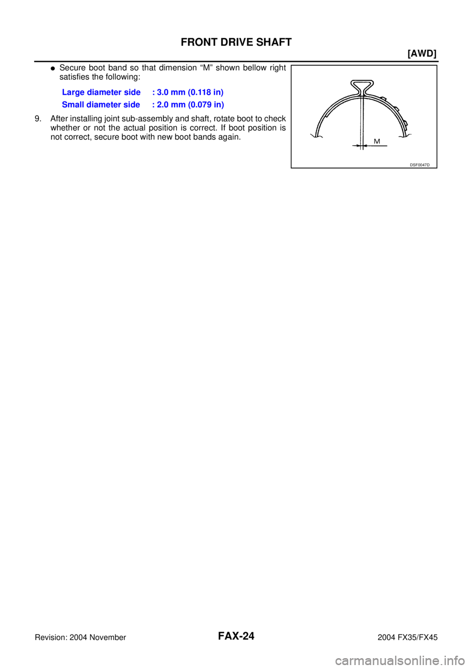
�Secure boot band so that dimension “M” shown bellow right
satisfies the following:
9. After installing joint sub-assembly and shaft, rotate boot to check
whether or not the actual position is correct. If boot position is
not correct, secure boot with new boot bands again.Large diameter side : 3.0 mm (0.118 in)
Small diameter side : 2.0 mm (0.079 in)
DSF0047D
Page 3054 of 4449
FRONT FINAL DRIVE ASSEMBLY
FFD-19
C
E
F
G
H
I
J
K
L
MA
B
FFD
Revision: 2004 November 2004 FX35/FX45
EXTENSION TUBE REPLACEMENT
1. Drain engine oil. Refer to MA-17, "Changing Engine Oil" (VQ35DE) or MA-24, "Changing Engine Oil"
(VK45DE).
2. Ply out the extension tube from the engine oil sump.
3. Remove the O-rings from the extension tube and replace them
with new ones.
4. Apply grease to the new extension tube O-rings.
5. Install the extension tube into the engine oil sump.
PRE-DISASSEMBLY INSPECTION
Before disassembling the front final drive, perform the following inspection.
To ta l P r e l o a d
1. Place the front final drive onto the attachment and secure it.
2. Drain the final drive oil.
3. Remove the carrier cover.
CAUTION:
When the carrier case is damaged, replace the final drive
assembly.
SDIA1632E
SDIA1633E
SDIA1634E
SDIA1648E
Page 3076 of 4449

FUEL SYSTEM
FL-3
C
D
E
F
G
H
I
J
K
L
MA
FL
Revision: 2004 November 2004 FX35/FX45
FUEL SYSTEMPFP:17503
Checking Fuel LinesABS005YX
Inspect fuel lines, fuel filler cap and fuel tank for improper attach-
ment, leaks, cracks, damage, loose connections, chafing or deterio-
ration.
If necessary, repair or replace damaged parts.
General PrecautionsABS005YY
WARNING:
When replacing fuel line parts, be sure to observe the following.
�Put a “CAUTION: INFLAMMABLE” sign in the workshop.
�Be sure to work in a well ventilated area and furnish workshop with a CO2 fire extinguisher.
�Do not smoke while servicing fuel system. Keep open flames and sparks away from the work area.
CAUTION:
�Before removing fuel line parts, carry out the following procedures:
–Put drained fuel in an explosion-proof container and put the lid on securely. Keep the container in
safe area.
–Release fuel pressure from the fuel lines. Refer to EC-51, "FUEL PRESSURE RELEASE" (VQ35DE)
or EC-700, "
FUEL PRESSURE RELEASE" (VK45DE).
–Disconnect negative battery terminal.
�Always replace O-ring and clamps with new ones.
�Do not kink or twist tubes when they are being installed.
�Do not tighten hose clamps excessively to avoid damaging hoses.
�After connecting fuel tube quick connectors, make sure
quick connectors are secure.
Ensure that connector and resin tube do not contact any
adjacent parts.
�After installing tubes, make sure there is no fuel leakage at
connections in the following steps.
–Apply fuel pressure to fuel lines with turning ignition switch
“ON” (with engine stopped). Then check for fuel leaks at
connections.
–Start engine and rev it up and check for fuel leaks at con-
nections.
�Use only a genuine NISSAN fuel filler cap as a replacement.
If an incorrect fuel filler cap is used, the “MIL” may come
on.
�For servicing “Evaporative Emission System” parts, refer to
EC-643, "
EVAPORATIVE EMISSION SYSTEM" (VQ35DE) or
EC-1320, "
EVAPORATIVE EMISSION SYSTEM" (VK45DE).
�For servicing“On Board Refueling Vapor Recovery (ORVR)”
parts, refer to EC-650, "
ON BOARD REFUELING VAPOR
RECOVERY (ORVR)" (VQ35DE) or EC-1327, "ON BOARD
REFUELING VAPOR RECOVERY (ORVR)" (VK45DE).
SMA803A
SBIA0504E
Page 3080 of 4449

FUEL LEVEL SENSOR UNIT, FUEL FILTER AND FUEL PUMP ASSEMBLY
FL-7
C
D
E
F
G
H
I
J
K
L
MA
FL
Revision: 2004 November 2004 FX35/FX45
Main and Sub Fuel Level Sensor Unit
�When installing fuel hose connector insert them fully until a click
sound of full stopper engagement is heard.
�Face main and sub fuel level sensor units as shown in the fig-
ure, and install them with the knock pin on back aligned with pin
hole on fuel tank.
�Install retainer so that its notch becomes parallel with the notch
on fuel tank.
�Tighten retainer mounting bolts evenly.
Quick Connector
Connect quick connector as follows:
1. Check the connection for damage or any foreign materials.
2. Align the connector with the tube, then insert the connector straight into the tube until a click sound is
heard.
3. After connecting, make sure that the connection is secure by following method.
�Pull the tube and the connector to make sure they are
securely connected.
�Visually confirm that the two retainer tabs are connected to
the connector.
INSPECTION AFTER INSTALLATION
Use the following procedure to check for fuel leaks.
PBIC1579E
PBIC1065E
PBIC1652E
PBIC1653E
Page 3082 of 4449
FUEL LEVEL SENSOR UNIT, FUEL FILTER AND FUEL PUMP ASSEMBLY
FL-9
C
D
E
F
G
H
I
J
K
L
MA
FL
Revision: 2004 November 2004 FX35/FX45
ASSEMBLY
1. Check for damage of fuel level sensor unit installation position on the side of fuel filter and fuel pump
assembly.
2. Slide fuel level sensor unit until it aligns to installation groove, then insert it until stop.
�After inserting, apply force in reverse direction (removal direction) to ensure it cannot be pulled out.
3. Connect harness connector.
�Securely insert harness connector until it stops.
![INFINITI FX35 2004 Service Manual FRONT DRIVE SHAFT
FAX-21
[AWD]
C
E
F
G
H
I
J
K
L
MA
B
FA X
Revision: 2004 November 2004 FX35/FX45
NOTE:
Housing and spider assembly are components which are used as a set.
ASSEMBLY
Front Final Drive A](/manual-img/42/57021/w960_57021-3029.png "INFINITI FX35 2004 Service Manual FRONT DRIVE SHAFT
FAX-21
[AWD]
C
E
F
G
H
I
J
K
L
MA
B
FA X
Revision: 2004 November 2004 FX35/FX45
NOTE:
Housing and spider assembly are components which are used as a set.
ASSEMBLY
Front Final Drive A")
 or M")
