Page 4267 of 4449
SRS-26
TROUBLE DIAGNOSIS
Revision: 2004 November 2004 FX35/FX45
6. Touch “SELF-DIAG [PAST]”.
7. If diagnostic codes are displayed on “SELF-DIAG [PAST]”, go to
step 10.
If no malfunction is detected on “SELF-DIAG [PAST]”, touch
“BACK” and go back to “SELECT DIAG MODE”.
8. Touch “TROUBLE DIAG RECORD”.
NOTE:
With “TROUBLE DIAG RECORD”, diagnosis results previously
erased by a reset operation can be displayed.
9. Diagnostic code is displayed on “TROUBLE DIAG RECORD”.
10. Touch “PRINT”.
11. Compare diagnostic codes to SRS-25, "
DIAGNOSTIC PROCE-
DURE 5" .
12. Touch “BACK” key of CONSULT-II until “SELECT SYSTEM”
appears.
13. Turn ignition switch OFF, then turn off and disconnect CON-
SULT-II, and both battery cables.
14. Repair the system as outlined by the “Repair order” in “Intermit-
tent Malfunction Diagnostic Code Chart”, that corresponds to the
SRS697
SRS700
SRS702
SRS697
SHIA0182E
Page 4296 of 4449

DISPOSAL OF AIR BAG MODULE AND SEAT BELT PRE-TENSIONER
SRS-55
C
D
E
F
G
I
J
K
L
MA
B
SRS
Revision: 2004 November 2004 FX35/FX45
DEPLOYMENT OF AIR BAG MODULE AND SEAT BELT PRE-TENSIONER WHILE MOUNTED IN
VEHICLE
When disposing of a vehicle, deploy air bag module and seat belt pre-tensioners while they are mounted in
vehicle.
CAUTION:
When deploying air bag module or seat belt pre-tensioner, ensure vehicle is empty.
1. Disconnect both the vehicle battery cables and wait 3 minutes.
2. Disconnect air bag module and seat belt pre-tensioner connector.
3. Connect deployment tool [SST: KV99106400 (J38381)] to air bag module.
For front passenger air bag module, attach deployment tool adapter (SST: J38381-65) to the tool connec-
tor. For side air bag module, attach deployment tool adapter [SST: KV99108300 (J38381-35)]. For driver
air bag module, side curtain air bag module and seat belt pre-tensioner, attach deployment tool adapter
(SST: J38381-80).
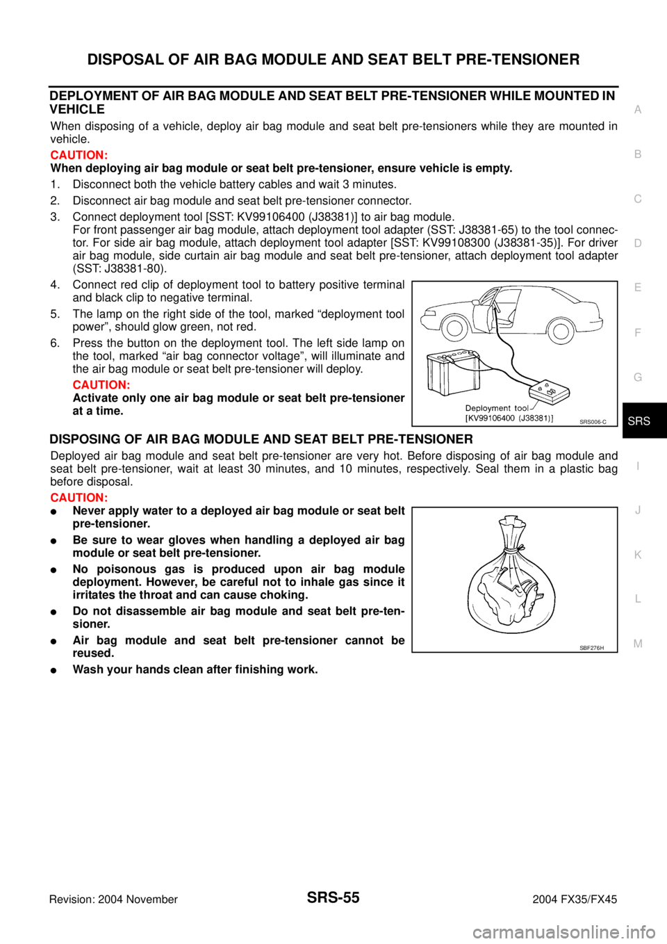
4. Connect red clip of deployment tool to battery positive terminal
and black clip to negative terminal.
5. The lamp on the right side of the tool, marked “deployment tool
power”, should glow green, not red.
6. Press the button on the deployment tool. The left side lamp on
the tool, marked “air bag connector voltage”, will illuminate and
the air bag module or seat belt pre-tensioner will deploy.
CAUTION:
Activate only one air bag module or seat belt pre-tensioner
at a time.
DISPOSING OF AIR BAG MODULE AND SEAT BELT PRE-TENSIONER
Deployed air bag module and seat belt pre-tensioner are very hot. Before disposing of air bag module and
seat belt pre-tensioner, wait at least 30 minutes, and 10 minutes, respectively. Seal them in a plastic bag
before disposal.
CAUTION:
�Never apply water to a deployed air bag module or seat belt
pre-tensioner.
�Be sure to wear gloves when handling a deployed air bag
module or seat belt pre-tensioner.
�No poisonous gas is produced upon air bag module
deployment. However, be careful not to inhale gas since it
irritates the throat and can cause choking.
�Do not disassemble air bag module and seat belt pre-ten-
sioner.
�Air bag module and seat belt pre-tensioner cannot be
reused.
�Wash your hands clean after finishing work.
SRS006-C
SBF276H
Page 4310 of 4449

AWD SYSTEM
TF-9
C
E
F
G
H
I
J
K
L
MA
B
TF
Revision: 2004 November 2004 FX35/FX45
AWD SYSTEMPFP:41650
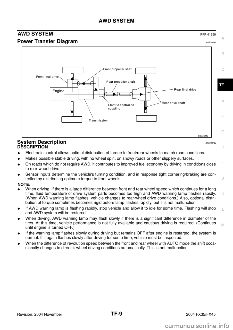
Power Transfer DiagramADS000RV
System DescriptionADS000RW
DESCRIPTION
�Electronic control allows optimal distribution of torque to front/rear wheels to match road conditions.
�Makes possible stable driving, with no wheel spin, on snowy roads or other slippery surfaces.
�On roads which do not require AWD, it contributes to improved fuel economy by driving in conditions close
to rear-wheel drive.
�Sensor inputs determine the vehicle's turning condition, and in response tight cornering/braking are con-
trolled by distributing optimum torque to front wheels.
NOTE:
�When driving, if there is a large difference between front and rear wheel speed which continues for a long
time, fluid temperature of drive system parts becomes too high and AWD warning lamp flashes rapidly.
(When AWD warning lamp flashes, vehicle changes to rear-wheel drive conditions.) Also, optional distri-
bution of torque sometimes becomes rigid before lamp flashes rapidly, but it is not malfunction.
�If AWD warning lamp is flashing rapidly, stop vehicle and allow it to idle for some time. Flashing will stop
and AWD system will be restored.
�When driving, AWD warning lamp may flash slowly if there is a significant difference in diameter of the
tires. At this time, vehicle performance is not fully available and cautious driving is required. (Continues
until engine is turned OFF.)
�If the warning lamp flashes slowly during driving but remains OFF after engine is restarted, the system is
normal. If it again flashes slowly after driving for some time, vehicle must be inspected.
�When the difference of revolution speed between the front and rear wheel with AUTO mode the shift occa-
sionally changes to direct 4-wheel driving conditions automatically. This is not malfunction.
SDIA1611E
Page 4311 of 4449
TF-10
AWD SYSTEM
Revision: 2004 November 2004 FX35/FX45
ELECTRIC CONTROLLED COUPLING
Operation principle
1. AWD control unit supplies command current to electric controlled coupling (AWD solenoid).
2. Control clutch is engaged by electromagnet and torque is detected in control clutch.
3. The cam operates in response to control clutch torque and applies pressure to main clutch.
4. Main clutch transmits torque to front wheels according to pressing power.
�Transmission torque to front wheels is determined according
to command current.
AWD CONTROL UNIT
�Controls distribution of drive power between rear-wheel drive
(0:100) and AWD (50:50) conditions according to signals from
sensors.
�Self-diagnosis can be done with CONSULT-II.
SDIA2270E
SDIA1844E
SDIA2273E
Page 4321 of 4449
![INFINITI FX35 2004 Service Manual TF-20
TROUBLE DIAGNOSIS
Revision: 2004 November 2004 FX35/FX45
*: The values are changed by throttle opening and engine speed.RR RH SENSOR [km/h] or [mph]Wheel speed (Rear wheel
right)Vehicle stopped INFINITI FX35 2004 Service Manual TF-20
TROUBLE DIAGNOSIS
Revision: 2004 November 2004 FX35/FX45
*: The values are changed by throttle opening and engine speed.RR RH SENSOR [km/h] or [mph]Wheel speed (Rear wheel
right)Vehicle stopped](/manual-img/42/57021/w960_57021-4320.png)
TF-20
TROUBLE DIAGNOSIS
Revision: 2004 November 2004 FX35/FX45
*: The values are changed by throttle opening and engine speed.RR RH SENSOR [km/h] or [mph]Wheel speed (Rear wheel
right)Vehicle stopped 0.00 km/h (0.00 mph)
Vehicle running
CAUTION:
Check air pressure of tire under
standard condition.Approximately equal to
the indication on speed-
ometer (Inside of ±10%)
RR LH SENSOR [km/h] or [mph]Wheel speed (Rear wheel
left)Vehicle stopped 0.00 km/h (0.00 mph)
Vehicle running
CAUTION:
Check air pressure of tire under
standard condition.Approximately equal to
the indication on speed-
ometer (Inside of ±10%)
BATTERY VOLT [V]Power supply voltage for
AWD control unitIgnition switch: ON Battery voltage
THRTL POS SEN [%] Throttle opening conditionWhen depressing accelerator pedal
(Value rises gradually in response to
throttle position.)0 - 100%
ETS SOLENOID [A]Monitored value of current at
AWD solenoidEngine running
�At idle speedApprox. 0.000A
Engine running
�When depressing accelerator
pedalApprox. 0.000 - 2.400A*
STOP LAMP SW [ON/OFF]Condition of brake pedal
operationBrake pedal: Depressed ON
Brake pedal: Released OFF
ENG SPEED SIG [RUN/STOP] Condition of engine runningEngine stopped
(Engine speed: Less than 400 rpm)STOP
Engine running
(Engine speed: 400 rpm or more)RUN
ETS ACTUATOR [ON/OFF]Operating condition of AWD
actuator relay (integrated in
AWD control unit)Engine stopped (Ignition
switch: ON)OFF
Engine running ON
4WD WARN LAMP [ON/OFF] AWD warning lamp conditionAWD warning lamp: ON ON
AWD warning lamp: OFF OFF
4WD MODE MON [AUTO] Control status of AWD Engine running AUTO
DIS-TIRE MONI [mm]Improper size tire installed
conditionVehicle running with normal size tire
installed0-4 mm
Vehicle running with improper size
tire installed (Front/rear tire size dif-
ference, wear condition)4-8 mm, 8- mm
P BRAKE SW [ON/OFF] Condition of parking brakeParking brake operated ON
Parking brake not operated OFF Monitored item [Unit] Content Condition Display value
Page 4341 of 4449
TF-40
REAR OIL SEAL
Revision: 2004 November 2004 FX35/FX45
REAR OIL SEALPFP:33140
Removal and InstallationADS000RQ
REMOVAL
1. Remove the rear propeller shaft. Refer to PR-6, "REAR PROPELLER SHAFT" .
2. Remove companion flange lock nut using the flange wrench.
3. Put matching mark on the end of the main shaft corresponding
to the B position matching mark on the companion flange.
CAUTION:
�For matching mark, use paint. Do not damage main shaft.
�The mark on the transfer companion flange indicates the
maximum vertical runout position.
4. Remove the companion flange using a puller.
5. Remove the rear oil seal using a tool.
CAUTION:
Be careful not to damage the rear case.Tool number : KV38108300 (J44195)
SDIA1784E
SDIA1798E
SDIA1785E
Tool number : KV381054S0 (J34286)
SDIA1786E
Page 4347 of 4449
TF-46
TRANSFER ASSEMBLY
Revision: 2004 November 2004 FX35/FX45
4. Remove snap ring from front case.
5. Remove main shaft bearing from front case.
Rear Case
1. Remove the drive chain and front drive shaft from rear case.
2. Remove companion flange lock nut from main shaft using the
flange wrench.
3. Put matching mark on the end of the main shaft corresponding
to the B position matching mark on the companion flange.
SDIA1601E
SDIA1595E
SDIA1693E
Tool number : KV38108300 (J44195)
SDIA1694E
SDIA1798E
Page 4367 of 4449
WT-10
TROUBLE DIAGNOSES
Revision: 2004 November 2004 FX35/FX45
TROUBLE DIAGNOSESPFP:00004
SchematicAES000NS
TEWM0045E