Page 2897 of 4449
![INFINITI FX35 2004 Service Manual EM-172
[VK45DE]
AIR CLEANER AND AIR DUCT
Revision: 2004 November 2004 FX35/FX45
AIR CLEANER AND AIR DUCTPFP:16500
Removal and InstallationABS006IB
REMOVAL
1. Remove engine cover with power tool. Refer](/manual-img/42/57021/w960_57021-2896.png "INFINITI FX35 2004 Service Manual EM-172
[VK45DE]
AIR CLEANER AND AIR DUCT
Revision: 2004 November 2004 FX35/FX45
AIR CLEANER AND AIR DUCTPFP:16500
Removal and InstallationABS006IB
REMOVAL
1. Remove engine cover with power tool. Refer")
EM-172
[VK45DE]
AIR CLEANER AND AIR DUCT
Revision: 2004 November 2004 FX35/FX45
AIR CLEANER AND AIR DUCTPFP:16500
Removal and InstallationABS006IB
REMOVAL
1. Remove engine cover with power tool. Refer to EM-168, "ENGINE ROOM COVER" .
2. Disconnect harness connector from mass air flow sensor.
3. Disconnect vacuum hose and PCV hose.
4. Remove air duct (inlet), air cleaner case and mass air flow sensor assembly, air duct and resonator
assembly disconnecting their joints.
�Add marks as necessary for easier installation.
5. Remove mass air flow sensor from air cleaner case.
CAUTION:
Handle mass air flow sensor with following cares.
�Do not shock it.
�Do not disassemble it.
�Do not touch its sensor.
INSTALLATION
Note to the following, and install in the reverse order of removal.
1. Air duct and resonator assembly 2. Bracket 3. Vacuum hose
4. Mass air flow sensor 5. O-ring 6. Air cleaner case
7. Air cleaner filter 8. Cover 9. Air cleaner case
10. Resonator 11. Mounting rubber 12. Air duct (inlet)
13. Clip
PBIC1657E
Page 2899 of 4449
EM-174
[VK45DE]
INTAKE MANIFOLD
Revision: 2004 November 2004 FX35/FX45
INTAKE MANIFOLDPFP:14003
Removal and InstallationABS006IC
REMOVAL
WARNING:
To avoid the danger of being scalded, never drain the engine coolant when the engine is hot.
1. PCV tube 2. Engine cover rear bracket 3.EVAP canister purge control sole-
noid valve
4. EVAP hose 5. EVAP tube 6. EVAP hose
7. Vacuum gallery 8. Engine cover front bracket 9. Vacuum tank
10. VIAS control solenoid valve 11. Water gallery 12. Gasket
13. Intake manifold (lower) 14. Gasket 15. Water hose
16. Intake manifold adapter 17. Electric throttle control actuator 18. Gasket
19. Intake manifold (upper) 20. Resonator 21. EVAP service port
PBIC3502E
Page 2900 of 4449
![INFINITI FX35 2004 Service Manual INTAKE MANIFOLD
EM-175
[VK45DE]
C
D
E
F
G
H
I
J
K
L
MA
EM
Revision: 2004 November 2004 FX35/FX45
1. Remove engine cover with power tool. Refer to EM-168, "ENGINE ROOM COVER" .
2. Release fuel pressure](/manual-img/42/57021/w960_57021-2899.png "INFINITI FX35 2004 Service Manual INTAKE MANIFOLD
EM-175
[VK45DE]
C
D
E
F
G
H
I
J
K
L
MA
EM
Revision: 2004 November 2004 FX35/FX45
1. Remove engine cover with power tool. Refer to EM-168, \"ENGINE ROOM COVER\" .
2. Release fuel pressure")
INTAKE MANIFOLD
EM-175
[VK45DE]
C
D
E
F
G
H
I
J
K
L
MA
EM
Revision: 2004 November 2004 FX35/FX45
1. Remove engine cover with power tool. Refer to EM-168, "ENGINE ROOM COVER" .
2. Release fuel pressure. Refer to EC-700, "
FUEL PRESSURE RELEASE" .
3. Drain engine coolant. Refer to CO-36, "
Changing Engine Coolant" .
4. Remove air duct (inlet), air cleaner case and mass air flow sensor assembly, air duct and resonator
assembly. Refer to EM-172, "
AIR CLEANER AND AIR DUCT" .
5. Disconnect fuel feed hose quick connector on engine side.
Refer to EM-188, "
FUEL INJECTOR AND FUEL TUBE" .
6. Remove fuel damper and fuel hose assembly. Refer to EM-188, "
FUEL INJECTOR AND FUEL TUBE" .
CAUTION:
�While hoses are disconnected, plug them to prevent fuel from draining.
�Do not separate fuel damper and fuel hose.
7. Remove or disconnect harnesses, brackets, vacuum hose, vacuum gallery and PCV hose and tube from
intake manifold (upper).
8. Remove electric throttle control actuator as follows:
a. Disconnect harness connector.
b. Loosen mounting bolts diagonally.
CAUTION:
�Handle carefully to avoid any shock to electric throttle control actuator.
�Do not disassemble.
9. Disconnect water hoses from water gallery.
10. Remove intake manifold adaptor and water gallery.
11. Loosen bolts in reverse order as shown in the figure to remove
intake manifold (upper) with power tool.
12. Remove vacuum tank form intake manifold (lower).
13. Remove fuel injector and fuel tube assembly. Refer to EM-188, "
FUEL INJECTOR AND FUEL TUBE" .
14. Loosen bolts in reverse order as shown in the figure to remove
intake manifold (lower) with power tool.
SBIA0353E
PBIC0014E
PBIC0015E
Page 2903 of 4449
![INFINITI FX35 2004 Service Manual EM-178
[VK45DE]
EXHAUST MANIFOLD AND THREE WAY CATALYST
Revision: 2004 November 2004 FX35/FX45
EXHAUST MANIFOLD AND THREE WAY CATALYSTPFP:14004
Removal and InstallationABS006ID
REMOVAL
WARNING:
Perfor](/manual-img/42/57021/w960_57021-2902.png "INFINITI FX35 2004 Service Manual EM-178
[VK45DE]
EXHAUST MANIFOLD AND THREE WAY CATALYST
Revision: 2004 November 2004 FX35/FX45
EXHAUST MANIFOLD AND THREE WAY CATALYSTPFP:14004
Removal and InstallationABS006ID
REMOVAL
WARNING:
Perfor")
EM-178
[VK45DE]
EXHAUST MANIFOLD AND THREE WAY CATALYST
Revision: 2004 November 2004 FX35/FX45
EXHAUST MANIFOLD AND THREE WAY CATALYSTPFP:14004
Removal and InstallationABS006ID
REMOVAL
WARNING:
Perform the work, when the exhaust and cooling system have completely cooled down.
1. Remove engine cover with power tool. Refer to EM-168, "
ENGINE ROOM COVER" .
2. Remove front and rear engine undercovers with power tool.
3. Remove air duct (inlet), air cleaner case and mass air flow sensor assembly, air duct and resonator
assembly. Refer to EM-172, "
AIR CLEANER AND AIR DUCT" .
4. Remove front cross bar. Refer to FSU-6, "
FRONT SUSPENSION ASSEMBLY" .
5. Drain engine coolant from radiator. Refer to CO-36, "
Changing Engine Coolant" .
CAUTION:
�Perform this step when engine is cold.
�Do not spill engine coolant on drive belts.
6. Remove radiator. Refer to CO-39, "
RADIATOR" .
7. Remove drive belts. Refer to EM-169, "
DRIVE BELTS" .
8. Remove heated oxygen sensors as follows:
a. Disconnect harness connector of each heated oxygen sensors.
1. Heated oxygen sensor 1 (bank 2) 2. Exhaust manifold cover (right bank) 3. Exhaust manifold (right bank)
4. Gasket 5. Exhaust manifold (left bank) 6. Exhaust manifold cover (left bank)
7. Heated oxygen sensor 1 (bank 1) 8. Three way catalyst cover (right bank) 9. Three way catalyst (right bank)
10. Heated oxygen sensor 2 (bank 2) 11. Gasket 12. Three way catalyst cover (left bank)
13. Heated oxygen sensor 2 (bank 1) 14. Three way catalyst (left bank) 15. Mounting bracket
16. Mounting bracket
PBIC3503E
Page 2904 of 4449
![INFINITI FX35 2004 Service Manual EXHAUST MANIFOLD AND THREE WAY CATALYST
EM-179
[VK45DE]
C
D
E
F
G
H
I
J
K
L
MA
EM
Revision: 2004 November 2004 FX35/FX45
b. Remove heated oxygen sensor 1 and 2 on both bank with
heated oxygen sensor w](/manual-img/42/57021/w960_57021-2903.png "INFINITI FX35 2004 Service Manual EXHAUST MANIFOLD AND THREE WAY CATALYST
EM-179
[VK45DE]
C
D
E
F
G
H
I
J
K
L
MA
EM
Revision: 2004 November 2004 FX35/FX45
b. Remove heated oxygen sensor 1 and 2 on both bank with
heated oxygen sensor w")
EXHAUST MANIFOLD AND THREE WAY CATALYST
EM-179
[VK45DE]
C
D
E
F
G
H
I
J
K
L
MA
EM
Revision: 2004 November 2004 FX35/FX45
b. Remove heated oxygen sensor 1 and 2 on both bank with
heated oxygen sensor wrench (SST).
�Put marks to identify installation positions of each heated oxy-
gen sensor.
CAUTION:
�Be careful not to damage heated oxygen sensor.
�Discard any heated oxygen sensor which has been
dropped from a height of more than 0.5 m (19.7 in) onto a
hard surface such as a concrete floor; replace with a new
one.
9. Remove exhaust mounting bracket between three way catalysts (right and left bank) and transmission.
Refer to EX-3, "
EXHAUST SYSTEM" .
10. Disconnect A/C piping from A/C compressor, then remove A/C compressor with power tool. Refer to AT C -
139, "Components" .
11. Remove alternator and bracket. Refer to SC-23, "
CHARGING SYSTEM" .
12. Remove exhaust front tube with power tool. Refer to EX-3, "
EXHAUST SYSTEM" .
13. Remove steering lower joint at power steering gear assembly side, and release steering lower shaft.
Refer to PS-19, "
POWER STEERING GEAR AND LINKAGE" .
14. Remove three way catalysts (right and left bank).
15. Remove exhaust manifold covers. (right and left bank)
16. Loosen mounting nuts in reverse order as shown in the figure to
remove exhaust manifold.
NOTE:
Disregard the numerical order No. 9 to 12 in removal.
17. Remove exhaust manifold gaskets.
CAUTION:
Cover engine openings to avoid entry of foreign materials.
PBIC2333E
PBIC2334E
PBIC1549E
Page 2918 of 4449
![INFINITI FX35 2004 Service Manual ROCKER COVER
EM-193
[VK45DE]
C
D
E
F
G
H
I
J
K
L
MA
EM
Revision: 2004 November 2004 FX35/FX45
ROCKER COVERPFP:13264
Removal and InstallationABS006II
REMOVAL
1. Remove engine cover with power tool. Ref](/manual-img/42/57021/w960_57021-2917.png "INFINITI FX35 2004 Service Manual ROCKER COVER
EM-193
[VK45DE]
C
D
E
F
G
H
I
J
K
L
MA
EM
Revision: 2004 November 2004 FX35/FX45
ROCKER COVERPFP:13264
Removal and InstallationABS006II
REMOVAL
1. Remove engine cover with power tool. Ref")
ROCKER COVER
EM-193
[VK45DE]
C
D
E
F
G
H
I
J
K
L
MA
EM
Revision: 2004 November 2004 FX35/FX45
ROCKER COVERPFP:13264
Removal and InstallationABS006II
REMOVAL
1. Remove engine cover with power tool. Refer to EM-168, "ENGINE ROOM COVER" .
2. Refer to the following for incidental works related to left bank.
a. Remove air duct (inlet), air cleaner case and mass air flow sensor assembly, air duct and resonator
assembly. Refer to EM-172, "
AIR CLEANER AND AIR DUCT" .
b. Move harness on upper rocker cover and its peripheral aside.
c. Remove harness brackets from camshaft bracket (No. 6). Refer to EM-208, "
CAMSHAFT" .
d. Remove electric throttle control actuator. Refer to EM-174, "
INTAKE MANIFOLD" .
e. Remove ignition coil. Refer to EM-185, "
IGNITION COIL" .
f. Remove PCV hose from PCV valve.
3. Refer to the following for incidental works related to right bank.
a. Move harness on upper rocker cover and its peripheral aside.
b. Remove ignition coil EM-185, "
IGNITION COIL" .
c. Remove PCV hose from PCV valve.
1. Rocker cover (left bank) 2. PCV valve 3. O-ring
4. Rocker cover gasket (left bank) 5. Rocker cover (right bank) 6. PCV valve
7. O-ring 8. Oil filler cap 9. Oil catcher
10. Rocker cover gasket (right bank)
PBIC2353E
Page 2919 of 4449
EM-194
[VK45DE]
ROCKER COVER
Revision: 2004 November 2004 FX35/FX45
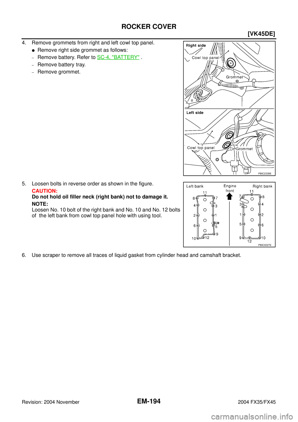
4. Remove grommets from right and left cowl top panel.
�Remove right side grommet as follows:
–Remove battery. Refer to SC-4, "BATTERY" .
–Remove battery tray.
–Remove grommet.
5. Loosen bolts in reverse order as shown in the figure.
CAUTION:
Do not hold oil filler neck (right bank) not to damage it.
NOTE:
Loosen No. 10 bolt of the right bank and No. 10 and No. 12 bolts
of the left bank from cowl top panel hole with using tool.
6. Use scraper to remove all traces of liquid gasket from cylinder head and camshaft bracket.
PBIC2339E
PBIC0027E
Page 2920 of 4449
![INFINITI FX35 2004 Service Manual ROCKER COVER
EM-195
[VK45DE]
C
D
E
F
G
H
I
J
K
L
MA
EM
Revision: 2004 November 2004 FX35/FX45
INSTALLATION
1. Apply liquid gasket to joint part of cylinder head and camshaft
bracket as follows:
NOTE:](/manual-img/42/57021/w960_57021-2919.png "INFINITI FX35 2004 Service Manual ROCKER COVER
EM-195
[VK45DE]
C
D
E
F
G
H
I
J
K
L
MA
EM
Revision: 2004 November 2004 FX35/FX45
INSTALLATION
1. Apply liquid gasket to joint part of cylinder head and camshaft
bracket as follows:
NOTE:")
ROCKER COVER
EM-195
[VK45DE]
C
D
E
F
G
H
I
J
K
L
MA
EM
Revision: 2004 November 2004 FX35/FX45
INSTALLATION
1. Apply liquid gasket to joint part of cylinder head and camshaft
bracket as follows:
NOTE:
The figure shows an example of left bank side [zoomed in
shows camshaft bracket (No. 1)]. Apply only to camshaft bracket
(No. 1) for right bank side.
a. Refer to the figure “a” to apply liquid gasket to joint part of cam-
shaft bracket (both No. 1 and No. 6) and cylinder head.
b. Refer to the figure “b” to apply liquid gasket in 90 degrees to the
figure “a”.
Use Genuine RTV Silicone Sealant or equivalent. Refer to
GI-48, "
RECOMMENDED CHEMICAL PRODUCTS AND
SEALANTS" .
2. Install rocker cover.
�Check if rocker cover gasket is not dropped from installation groove of rocker cover.
3. Tighten bolts in two steps separately in numerical order as
shown in the figure.
CAUTION:
Do not hold oil filler neck (right bank) not to damage it.
NOTE:
Tighten No. 10 bolt of the right bank and No. 10 and No. 12 bolts
of the left bank from cowl top panel hole with using tool.
4. Install in the reverse order of removal after this step.
PBIC2444E
1st step : 2.0 N·m (0.2 kg-m, 18 in-lb)
2nd step : 8.3 N·m (0.85 kg-m, 73 in-lb)
PBIC0027E
![INFINITI FX35 2004 Service Manual EM-174
[VK45DE]
INTAKE MANIFOLD
Revision: 2004 November 2004 FX35/FX45
INTAKE MANIFOLDPFP:14003
Removal and InstallationABS006IC
REMOVAL
WARNING:
To avoid the danger of being scalded, never drain the](/manual-img/42/57021/w960_57021-2898.png "INFINITI FX35 2004 Service Manual EM-174
[VK45DE]
INTAKE MANIFOLD
Revision: 2004 November 2004 FX35/FX45
INTAKE MANIFOLDPFP:14003
Removal and InstallationABS006IC
REMOVAL
WARNING:
To avoid the danger of being scalded, never drain the")