Page 3227 of 4449
GW-68
POWER WINDOW SYSTEM
Revision: 2004 November 2004 FX35/FX45
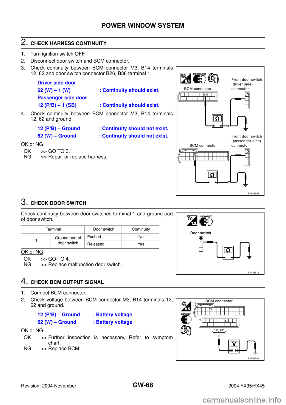
2. CHECK HARNESS CONTINUITY
1. Turn ignition switch OFF.
2. Disconnect door switch and BCM connector.
3. Check continuity between BCM connector M3, B14 terminals
12, 62 and door switch connector B26, B36 terminal 1.
4. Check continuity between BCM connector M3, B14 terminals
12, 62 and ground.
OK or NG
OK >> GO TO 3.
NG >> Repair or replace harness.
3. CHECK DOOR SWITCH
Check continuity between door switches terminal 1 and ground part
of door switch.
OK or NG
OK >> GO TO 4.
NG >> Replace malfunction door switch.
4. CHECK BCM OUTPUT SIGNAL
1. Connect BCM connector.
2. Check voltage between BCM connector M3, B14 terminals 12,
62 and ground.
OK or NG
OK >> Further inspection is necessary, Refer to symptom
chart.
NG >> Replace BCM.Driver side door
62 (W) – 1 (W) : Continuity should exist.
Passenger side door
12 (P/B) – 1 (SB) : Continuity should exist.
12 (P/B) – Ground : Continuity should not exist.
62 (W) – Ground : Continuity should not exist.
PIIA6159E
Terminal Door switch Continuity
1Ground part of
door switchPushed No
Released Yes
PIIA3351E
12 (P/B) – Ground : Battery voltage
62 (W) – Ground : Battery voltage
PIIA6158E
Page 3228 of 4449
POWER WINDOW SYSTEM
GW-69
C
D
E
F
G
H
J
K
L
MA
B
GW
Revision: 2004 November 2004 FX35/FX45
Front Door Key Cylinder Switch Check AIS004QU
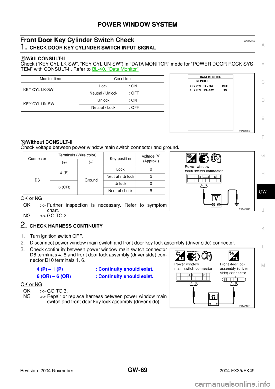
1. CHECK DOOR KEY CYLINDER SWITCH INPUT SIGNAL
With CONSULT-II
Check (“KEY CYL LK-SW”, “KEY CYL UN-SW”) in “DATA MONITOR” mode for “POWER DOOR ROCK SYS-
TEM” with CONSULT-II. Refer to BL-40, "
Data Monitor"
Without CONSULT-II
Check voltage between power window main switch connector and ground.
OK or NG
OK >> Further inspection is necessary. Refer to symptom
chart.
NG >> GO TO 2.
2. CHECK HARNESS CONTINUITY
1. Turn ignition switch OFF.
2. Disconnect power window main switch and front door key lock assembly (driver side) connector.
3. Check continuity between power window main switch connector
D6 terminals 4, 6 and front door lock assembly (driver side) con-
nector D10 terminals 1, 6.
OK or NG
OK >> GO TO 3.
NG >> Repair or replace harness between power window main
switch and front door key lock assembly (driver side).
Monitor item Condition
KEY CYL LK-SWLock : ON
Neutral / Unlock : OFF
KEY CYL UN-SWUnlock : ON
Neutral / Lock : OFF
PIIA6285E
ConnectorTerminals (Wire color)
Key position Voltage [V]
(Approx.)
(+) (–)
D64 (P)
GroundLock 0
Neutral / Unlock 5
6 (OR)Unlock 0
Neutral / Lock 5
PIIA4211E
4 (P) – 1 (P) : Continuity should exist.
6 (OR) – 6 (OR) : Continuity should exist.
PIIA4212E
Page 3230 of 4449
POWER WINDOW SYSTEM
GW-71
C
D
E
F
G
H
J
K
L
MA
B
GW
Revision: 2004 November 2004 FX35/FX45
Power Window Serial Link Check (Passenger Side)AIS004QV
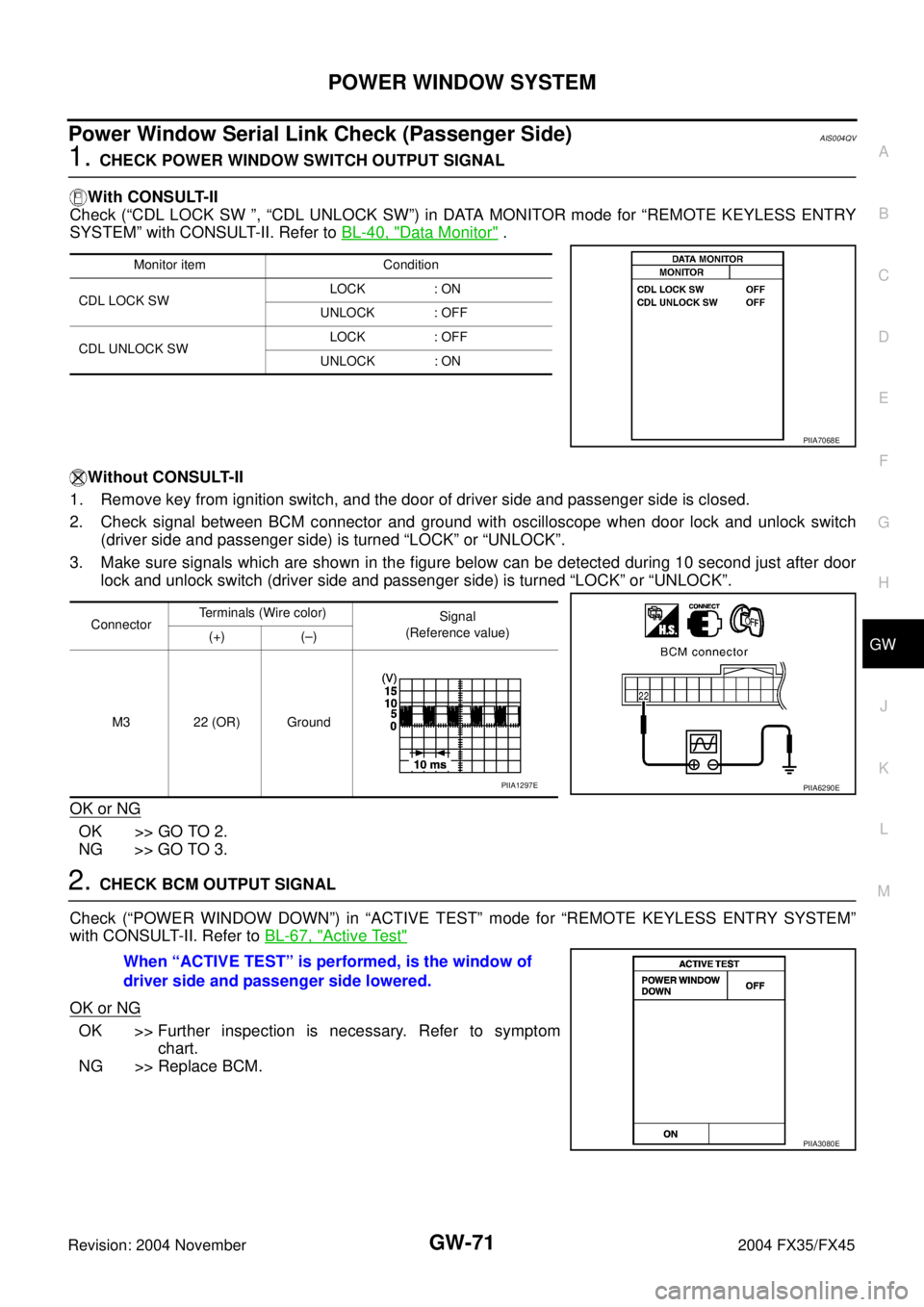
1. CHECK POWER WINDOW SWITCH OUTPUT SIGNAL
With CONSULT-II
Check (“CDL LOCK SW ”, “CDL UNLOCK SW”) in DATA MONITOR mode for “REMOTE KEYLESS ENTRY
SYSTEM” with CONSULT-II. Refer to BL-40, "
Data Monitor" .
Without CONSULT-II
1. Remove key from ignition switch, and the door of driver side and passenger side is closed.
2. Check signal between BCM connector and ground with oscilloscope when door lock and unlock switch
(driver side and passenger side) is turned “LOCK” or “UNLOCK”.
3. Make sure signals which are shown in the figure below can be detected during 10 second just after door
lock and unlock switch (driver side and passenger side) is turned “LOCK” or “UNLOCK”.
OK or NG
OK >> GO TO 2.
NG >> GO TO 3.
2. CHECK BCM OUTPUT SIGNAL
Check (“POWER WINDOW DOWN”) in “ACTIVE TEST” mode for “REMOTE KEYLESS ENTRY SYSTEM”
with CONSULT-II. Refer to BL-67, "
Active Test"
OK or NG
OK >> Further inspection is necessary. Refer to symptom
chart.
NG >> Replace BCM.
Monitor item Condition
CDL LOCK SW LOCK : ON
UNLOCK : OFF
CDL UNLOCK SW LOCK : OFF
UNLOCK : ON
PIIA7068E
ConnectorTerminals (Wire color)
Signal
(Reference value)
(+) (–)
M3 22 (OR) Ground
PIIA6290EPIIA1297E
When “ACTIVE TEST” is performed, is the window of
driver side and passenger side lowered.
PIIA3080E
Page 3231 of 4449
GW-72
POWER WINDOW SYSTEM
Revision: 2004 November 2004 FX35/FX45
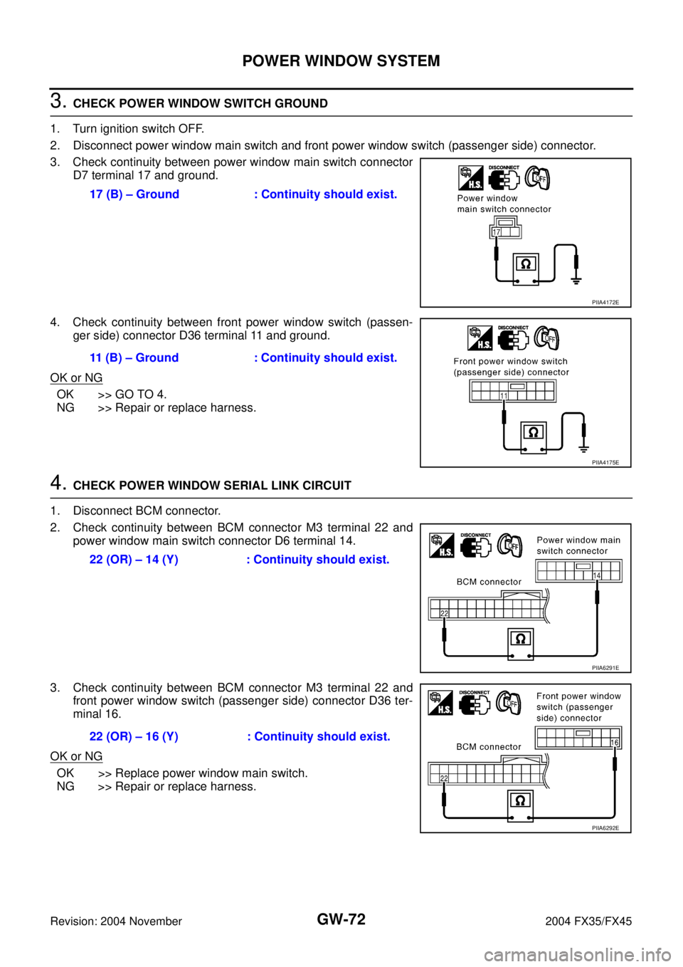
3. CHECK POWER WINDOW SWITCH GROUND
1. Turn ignition switch OFF.
2. Disconnect power window main switch and front power window switch (passenger side) connector.
3. Check continuity between power window main switch connector
D7 terminal 17 and ground.
4. Check continuity between front power window switch (passen-
ger side) connector D36 terminal 11 and ground.
OK or NG
OK >> GO TO 4.
NG >> Repair or replace harness.
4. CHECK POWER WINDOW SERIAL LINK CIRCUIT
1. Disconnect BCM connector.
2. Check continuity between BCM connector M3 terminal 22 and
power window main switch connector D6 terminal 14.
3. Check continuity between BCM connector M3 terminal 22 and
front power window switch (passenger side) connector D36 ter-
minal 16.
OK or NG
OK >> Replace power window main switch.
NG >> Repair or replace harness.17 (B) – Ground : Continuity should exist.
PIIA4172E
11 (B) – Ground : Continuity should exist.
PIIA4175E
22 (OR) – 14 (Y) : Continuity should exist.
PIIA6291E
22 (OR) – 16 (Y) : Continuity should exist.
PIIA6292E
Page 3232 of 4449
POWER WINDOW SYSTEM
GW-73
C
D
E
F
G
H
J
K
L
MA
B
GW
Revision: 2004 November 2004 FX35/FX45
Power Window Serial Link Check (Rear LH or RH) / With Front and Rear Power
Window Anti-pinch System
AIS004QW
1. CHECK POWER WINDOW SWITCH
Change with operative rear power window switch (LH or RH).
Whether operates normally is confirmed?
YES >> Replace rear power window switch (LH or RH).
NO >> GO TO 2.
2. CHECK HARNESS CONTINUITY
1. Turn ignition switch OFF.
2. Disconnect power window main switch and rear power window switch (LH or RH) connector.
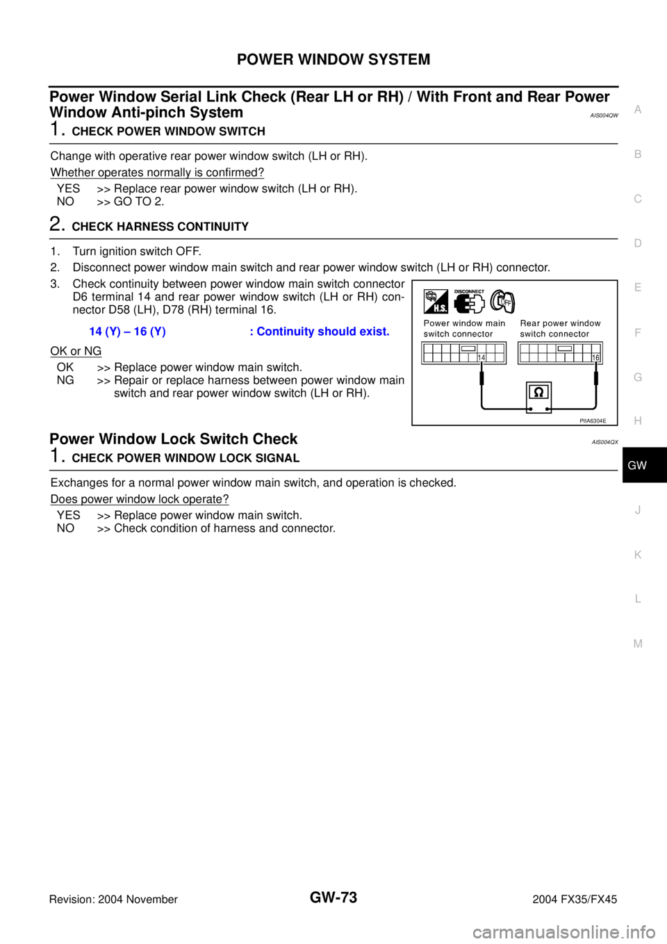
3. Check continuity between power window main switch connector
D6 terminal 14 and rear power window switch (LH or RH) con-
nector D58 (LH), D78 (RH) terminal 16.
OK or NG
OK >> Replace power window main switch.
NG >> Repair or replace harness between power window main
switch and rear power window switch (LH or RH).
Power Window Lock Switch CheckAIS004QX
1. CHECK POWER WINDOW LOCK SIGNAL
Exchanges for a normal power window main switch, and operation is checked.
Does power window lock operate?
YES >> Replace power window main switch.
NO >> Check condition of harness and connector.14 (Y) – 16 (Y) : Continuity should exist.
PIIA6304E
Page 3246 of 4449

REAR WINDOW DEFOGGER
GW-87
C
D
E
F
G
H
J
K
L
MA
B
GW
Revision: 2004 November 2004 FX35/FX45
�to A/C and AV switch terminal 1.
�through 50A fusible link (letter M , located in the fuse and fusible link box)
�to BCM terminal 55.
�through 15A fuse [No.22, located in the fuse block (J/B)]
�to BCM terminal 42.
With the ignition switch turned to ON or START position,
Power is supplied
�through 15A fuse [No.1, located in the fuse block (J/B)]
�to BCM terminal 38.
Ground is supplied
�to BCM terminal 49 and 52
�through body grounds M35, M45 and M85.
�to A/C and AV switch terminal 5
�through body grounds M35, M45 and M85.
�to IPDM E/R terminals 38 and 60
�through body grounds E21, E50 and E51.
When rear window defogger switch in A/C and AV switch is turned to ON,
Ground is supplied
�to BCM terminal 9
�through A/C and AV switch terminal 16
�through A/C and AV switch terminal 5
�through body grounds M35, M45 and M85.
Then rear window defogger switch is illuminated.
Then BCM recognizes that rear window defogger switch is turned to ON.
Then it sends rear window defogger switch signals to IPDM E/R, display control unit (with navigation system)
or display unit (without navigation system) via DATA LINE (CAN H, CAN L).
When display control unit (with navigation system) or display unit (without navigation system) receives rear
window defogger switch signals, and display on the screen.
When IPDM E/R receives rear window defogger switch signals,
Ground is supplied
�to rear window defogger relay terminal 2
�through IPDM E/R terminal 52
�through IPDM E/R terminals 38 and 60
�through body grounds E21, E50 and E51,
and then rear window defogger relay is energized.
When rear window defogger relay is turned ON,
Signals are transmitted,
�through rear window defogger relay terminals 5 and 7
�to rear window defogger terminal 1
�Rear window defogger terminal 2 is grounded through body grounds B15 and B45.
With power and ground supplied, rear window defogger filaments heat and defog the rear window.
When rear window defogger relay is turned to ON,
Power is supplied
�through rear window defogger relay terminal 7
�through fuse block (J/B) terminal 2C
�through 15A fuse [No. 8, located in the fuse block (J/B)]
�through fuse block (J/B) terminal 5B
�to door mirror defogger (driver side and passenger side) terminal 1.
Door mirror defogger (driver side and passenger side) terminal 2 is grounded through body grounds M35, M45
and M85.
With power and ground supplied, rear window defogger filaments heat and defog the rear window and door
mirror defogger filaments heat and defog the mirror.
Page 3253 of 4449

GW-94
REAR WINDOW DEFOGGER
Revision: 2004 November 2004 FX35/FX45
Terminal and Reference Value for BCMAIS004R4
Terminal and Reference Value for IPDM E/RAIS004R5
Work FlowAIS004R6
1. Check the symptom and customer's requests.
2. Understand the outline of system. Refer to GW-86, "
System Description" .
3. According to the trouble diagnosis chart, repair or replace the cause of the malfunction. Refer to GW-97,
"Trouble Diagnoses Symptom Chart" .
4. Does rear window defogger operate normally? YES: GO TO 5, NO: GO TO 3.
5. INSPECTION END.
Terminal Wire color Item ConditionVoltage (V)
(Approx.)
9L/WRear window defogger
switch signalWhen rear window defogger switch is pressed. 0
When rear window defogger switch is OFF. 5
38 W/L Ignition switch ON or START Ignition switch (ON or START position) Battery voltage
39 L CAN− H——
40 R CAN− L——
42 L/R Battery power supply — Battery voltage
49 B Ground (signal) — 0
52 B Ground (power) — 0
55 G Battery power supply — Battery voltage
Terminal Wire color Item ConditionVoltage (V)
(Approx.)
5 R Battery power supply — Battery voltage
6 W Battery power supply — Battery voltage
38 B Ground (Power) — 0
48 L CAN− H——
49 R CAN− L——
52 GRear window defogger relay
control signalWhen rear window defogger switch is ON. 0
When rear window defogger switch is OFF. Battery voltage
60 B Ground (Signal) — 0
Page 3254 of 4449
REAR WINDOW DEFOGGER
GW-95
C
D
E
F
G
H
J
K
L
MA
B
GW
Revision: 2004 November 2004 FX35/FX45
CONSULT-II Inspection ProcedureAIS004R7
CAUTION:
If CONSULT-II is used with no connection of CONSULT-II CONVERTER, malfunctions might be
detected in self-diagnosis depending on control unit which carry out CAN communication.
1. Turn ignition switch “OFF”.
2. Connect “CONSULT-II” and CONSULT-II CONVERTER to data
link connector.
3. Turn ignition switch “ON”.
4. Touch “START (NISSAN BASED VHCL)”.
5. Touch “BCM”.
If “BCM” is not indicated, go to GI-40
, “CONSULT-II Date Link
Connector (DLC) Circuit”
6. Touch “REAR DEFOGGER”.
PBIB1503E
MBIB0233E
LIIA0033E
LIIA0153E