Page 3305 of 4449
![INFINITI FX35 2004 Service Manual LAN-4
[CAN]
PRECAUTIONS
Revision: 2004 November 2004 FX35/FX45
[CAN]PRECAUTIONSPFP:00001
Precautions for Supplemental Restraint System (SRS) “AIR BAG” and “SEAT
BELT PRE-TENSIONER”
AKS007WY
T](/manual-img/42/57021/w960_57021-3304.png "INFINITI FX35 2004 Service Manual LAN-4
[CAN]
PRECAUTIONS
Revision: 2004 November 2004 FX35/FX45
[CAN]PRECAUTIONSPFP:00001
Precautions for Supplemental Restraint System (SRS) “AIR BAG” and “SEAT
BELT PRE-TENSIONER”
AKS007WY
T")
LAN-4
[CAN]
PRECAUTIONS
Revision: 2004 November 2004 FX35/FX45
[CAN]PRECAUTIONSPFP:00001
Precautions for Supplemental Restraint System (SRS) “AIR BAG” and “SEAT
BELT PRE-TENSIONER”
AKS007WY
The Supplemental Restraint System such as “AIR BAG” and “SEAT BELT PRE-TENSIONER”, used along
with a front seat belt, helps to reduce the risk or severity of injury to the driver and front passenger for certain
types of collision. This system includes seat belt switch inputs and dual stage front air bag modules. The SRS
system uses the seat belt switches to determine the front air bag deployment, and may only deploy one front
air bag, depending on the severity of a collision and whether the front occupants are belted or unbelted.
Information necessary to service the system safely is included in the SRS and SB section of this Service Man-
ual.
WARNING:
�To avoid rendering the SRS inoperative, which could increase the risk of personal injury or death
in the event of a collision which would result in air bag inflation, all maintenance must be per-
formed by an authorized NISSAN/INFINITI dealer.
�Improper maintenance, including incorrect removal and installation of the SRS, can lead to per-
sonal injury caused by unintentional activation of the system. For removal of Spiral Cable and Air
Bag Module, see the SRS section.
�Do not use electrical test equipment on any circuit related to the SRS unless instructed to in this
Service Manual. SRS wiring harnesses can be identified by yellow and/or orange harnesses or
harness connectors.
Precautions When Using CONSULT-IIAKS0058H
When connecting CONSULT-II to data link connector, connect them through CONSULT-II CONVERTER.
CAUTION:
If CONSULT-II is used with no connection of CONSULT-II CONVERTER, malfunctions might be
detected in self-diagnosis depending on control unit which carry out CAN communication.
CHECK POINTS FOR USING CONSULT-II
1. Has CONSULT-II been used without connecting CONSULT-II CONVERTER on this vehicle?
–If YES, GO TO 2.
–If NO, GO TO 5.
2. Is there any indication other than indications relating to CAN communication system in the self-diagnosis
results?
–If YES, GO TO 3.
–If NO, GO TO 4.
3. Based on self-diagnosis results unrelated to CAN communication, carry out the inspection.
4. Malfunctions may be detected in self-diagnosis depending on control units carrying out CAN communica-
tion. Therefore, erase the self-diagnosis results.
5. Diagnose CAN communication system. Refer to LAN-6, "
CAN Communication Unit" .
Precautions For Trouble DiagnosisAKS0058I
CAN SYSTEM
�Do not apply voltage of 7.0 V or higher to the measurement terminals.
�Use the tester with its open terminal voltage being 7.0 V or less.
�Be sure to turn ignition switch off and disconnect negative battery terminal before checking the circuit.
Page 3308 of 4449
![INFINITI FX35 2004 Service Manual CAN COMMUNICATION
LAN-7
[CAN]
C
D
E
F
G
H
I
J
L
MA
B
LAN
Revision: 2004 November 2004 FX35/FX45
�Ty pe 2
Input/output signal chart
T: Transmit R: Receive
SKIA6172E
Signals ECM TCMDis-
play
unitBCMS](/manual-img/42/57021/w960_57021-3307.png "INFINITI FX35 2004 Service Manual CAN COMMUNICATION
LAN-7
[CAN]
C
D
E
F
G
H
I
J
L
MA
B
LAN
Revision: 2004 November 2004 FX35/FX45
�Ty pe 2
Input/output signal chart
T: Transmit R: Receive
SKIA6172E
Signals ECM TCMDis-
play
unitBCMS")
CAN COMMUNICATION
LAN-7
[CAN]
C
D
E
F
G
H
I
J
L
MA
B
LAN
Revision: 2004 November 2004 FX35/FX45
�Ty pe 2
Input/output signal chart
T: Transmit R: Receive
SKIA6172E
Signals ECM TCMDis-
play
unitBCMSte er-
ing
angle
sensorUnified
meter
and
A/C
amp.ABS
actua-
tor and
electric
unit
(con-
trol
unit)Driver
seat
control
unitIPDM
E/R
Engine speed signal T R R R R
Engine status signal T R
Engine coolant temperature signal T R
A/T self-diagnosis signal R T
Accelerator pedal position signal T R R
Closed throttle position signal T R
Wide open throttle position signal T R
Battery voltage signal T R
Key switch signal T R
Ignition switch signal T R R
P range signal T R R
Stop lamp switch signal R T
Fuel consumption monitor signalTR
RT
Turbine revolution signal R T
Output shaft revolution signal R T
A/C switch signal R T
A/C compressor request signal TR
A/C compressor feedback signal T R
Blower fan motor switch signal R T
A/C switch/indicator signalTR
RT
Cooling fan speed request signal TR
Page 3311 of 4449
![INFINITI FX35 2004 Service Manual LAN-10
[CAN]
CAN COMMUNICATION
Revision: 2004 November 2004 FX35/FX45
A/T self-diagnosis signal R T
Accelerator pedal posi-
tion signal TR R R
Closed throttle position
signalTR R
Wide open throttle p](/manual-img/42/57021/w960_57021-3310.png "INFINITI FX35 2004 Service Manual LAN-10
[CAN]
CAN COMMUNICATION
Revision: 2004 November 2004 FX35/FX45
A/T self-diagnosis signal R T
Accelerator pedal posi-
tion signal TR R R
Closed throttle position
signalTR R
Wide open throttle p")
LAN-10
[CAN]
CAN COMMUNICATION
Revision: 2004 November 2004 FX35/FX45
A/T self-diagnosis signal R T
Accelerator pedal posi-
tion signal TR R R
Closed throttle position
signalTR R
Wide open throttle posi-
tion signalTR
Battery voltage signal T R
Key switch signal T R
Ignition switch signal T R R
P range signal T R R R
Stop lamp switch signal R T
ABS operation signal R T
TCS operation signal R T
VDC operation signal R T
Fuel consumption moni-
tor signalTR
RT
Turbine revolution signal R T R
Output shaft revolution
signalRT R
A/C switch signal R T
A/C compressor request
signalTR
A/C compressor feed-
back signalTR
Blower fan motor switch
signalRT
A/C switch/indicator sig-
nalTR
RT
Cooling fan speed
request signalTR
Position light request sig-
nalTR R
Low beam request signal T R
Low beam status signal RT
High beam request sig-
nalTR R
High beam status signal RT
Front fog light request
signalTR
Day time running light
request signalTR Signals ECM TCMDis-
play
con-
trol
unitLow
tire
pres-
sure
warn-
ing
con-
trol
unitICC
unitIntelli-
gent
Key
unitBCMSte er-
ing
angle
sen-
sorUni-
fied
meter
and
A/C
amp.ICC
sen-
sorABS
actu-
ator
and
elec-
tric
unit
(con-
trol
unit)Driver
seat
con-
trol
unitIPDM
E/R
Page 3314 of 4449
CAN COMMUNICATION
LAN-13
[CAN]
C
D
E
F
G
H
I
J
L
MA
B
LAN
Revision: 2004 November 2004 FX35/FX45
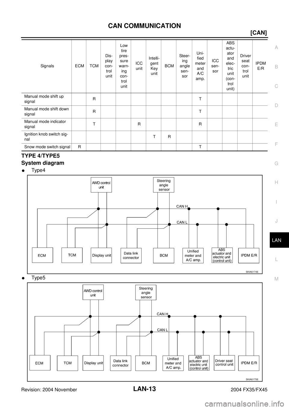
TYPE 4/TYPE5
System diagram
�Ty pe 4
�Ty pe 5
Manual mode shift up
signalRT
Manual mode shift down
signalRT
Manual mode indicator
signalTR R
Ignition knob switch sig-
nalTR
Snow mode switch signal R TSignals ECM TCMDis-
play
con-
trol
unitLow
tire
pres-
sure
warn-
ing
con-
trol
unitICC
unitIntelli-
gent
Key
unitBCMSteer-
ing
angle
sen-
sorUni-
fied
meter
and
A/C
amp.ICC
sen-
sorABS
actu-
ator
and
elec-
tric
unit
(con-
trol
unit)Driver
seat
con-
trol
unitIPDM
E/R
SKIA6174E
SKIA6175E
Page 3315 of 4449
![INFINITI FX35 2004 Service Manual LAN-14
[CAN]
CAN COMMUNICATION
Revision: 2004 November 2004 FX35/FX45
Input/output signal chart
T: Transmit R: Receive
Signals ECM TCMDis-
play
unitAWD
con-
trol
unitBCMSt e e r-
ing
angle
sens](/manual-img/42/57021/w960_57021-3314.png "INFINITI FX35 2004 Service Manual LAN-14
[CAN]
CAN COMMUNICATION
Revision: 2004 November 2004 FX35/FX45
Input/output signal chart
T: Transmit R: Receive
Signals ECM TCMDis-
play
unitAWD
con-
trol
unitBCMSt e e r-
ing
angle
sens")
LAN-14
[CAN]
CAN COMMUNICATION
Revision: 2004 November 2004 FX35/FX45
Input/output signal chart
T: Transmit R: Receive
Signals ECM TCMDis-
play
unitAWD
con-
trol
unitBCMSt e e r-
ing
angle
sensorUni-
fied
meter
and
A/C
amp.ABS
actua-
tor
and
elec-
tric
unit
(con-
trol
unit)Driver
seat
con-
trol
unitIPDM
E/R
A/T self-diagnosis signal R T
Stop lamp switch signal R R T
Battery voltage signal T R
Key switch signal T R
Ignition switch signal T R R
P range signal T R R
Closed throttle position signal T R
Wide open throttle position signal T R
Engine speed signal T R R R R R
Engine status signal T R
Engine coolant temperature signal T R
Accelerator pedal position signal T R R R
Fuel consumption monitor signalTR
RT
Turbine revolution signal R T
Output shaft revolution signal R T
A/C switch signal R T
A/C compressor request signal TR
A/C compressor feedback signal T R
Blower fan motor switch signal R T
A/C switch/indicator signalTR
RT
Cooling fan speed request signal TR
Position light request signal R T R R
Low beam request signal T R
Low beam status signal RT
High beam request signal T R R
High beam status signal RT
Front fog light request signal T R
Day time running light request signal T R
Turn LED burnout status signal R T
Vehicle speed signalRRT
RRR R T R
Sleep wake up signal T R R
Door switch signal R T R R R
Turn indicator signal T R
Key fob ID signal T R
Page 3318 of 4449
![INFINITI FX35 2004 Service Manual CAN COMMUNICATION
LAN-17
[CAN]
C
D
E
F
G
H
I
J
L
MA
B
LAN
Revision: 2004 November 2004 FX35/FX45
Ignition switch signal T R R
P range signal T R R R
Closed throttle posi-
tion signalTR R
Wide open thr](/manual-img/42/57021/w960_57021-3317.png "INFINITI FX35 2004 Service Manual CAN COMMUNICATION
LAN-17
[CAN]
C
D
E
F
G
H
I
J
L
MA
B
LAN
Revision: 2004 November 2004 FX35/FX45
Ignition switch signal T R R
P range signal T R R R
Closed throttle posi-
tion signalTR R
Wide open thr")
CAN COMMUNICATION
LAN-17
[CAN]
C
D
E
F
G
H
I
J
L
MA
B
LAN
Revision: 2004 November 2004 FX35/FX45
Ignition switch signal T R R
P range signal T R R R
Closed throttle posi-
tion signalTR R
Wide open throttle
position signalTR
Engine speed signal T R R R R R R
Engine status signal T R
Engine coolant tem-
perature signalTRR
Accelerator pedal
position signal TR R R R
Fuel consumption
monitor signalTR
RT
A/T self-diagnosis
signalRT
Turbine revolution
signalRT R
Output shaft revolu-
tion signalRT R
A/C switch signal R T
A/C compressor
request signalTR
A/C compressor
feedback signalTR
Blower fan motor
switch signalRT
A/C switch/indicator
signalTR
RT
Cooling fan speed
request signalTR
Position light request
signalRTRR
Low beam request
signalTR
Low beam status sig-
nalRT
High beam request
signalTR R
High beam status
signalRT
Front fog light
request signalTR Signals ECM TCMDis-
play
con-
trol
unitLow
tire
pres-
sure
warn-
ing
con-
trol
unitAW D
con-
trol
unitICC
unitIntel-
ligent
Key
unitBCMSteer-
ing
angle
sen-
sorUni-
fied
meter
and
A/C
amp.ICC
sen-
sorABS
actu-
ator
and
elec-
tric
unit
(con-
trol
unit)Driver
seat
con-
trol
unitIPDM
E/R
Page 3321 of 4449
LAN-20
[CAN]
CAN COMMUNICATION
Revision: 2004 November 2004 FX35/FX45
*: VK45DE engine model onlyA/T CHECK indica-
tor lamp signalTR
A/T position indica-
tor lamp signalTR
A/T shift schedule
change demand sig-
nalRT
Manual mode signal R T
Not manual mode
signalRT
Manual mode shift up
signalRT
Manual mode shift
down signalRT
Manual mode indica-
tor signalTR
Ignition knob switch
signalTR
Snow mode switch
signalRT
Current gear posi-
tion signal*RT
Next gear position
signal*RT
Shift change signal* R T
Shift pattern signal* R TSignals ECM TCMDis-
play
con-
trol
unitLow
tire
pres-
sure
warn-
ing
con-
trol
unitAWD
con-
trol
unitICC
unitIntel-
ligent
Key
unitBCMStee r-
ing
angle
sen-
sorUni-
fied
meter
and
A/C
amp.ICC
sen-
sorABS
actu-
ator
and
elec-
tric
unit
(con-
trol
unit)Driver
seat
con-
trol
unitIPDM
E/R
Page 3341 of 4449
LAN-40
[CAN]
CAN SYSTEM (TYPE 1)
Revision: 2004 November 2004 FX35/FX45
Case 13
Check CAN communication circuit. Refer to LAN-47, "CAN Communication Circuit Check" .
Case 14
Check IPDM E/R ignition relay circuit continuously sticks “OFF”. Refer to LAN-51, "IPDM E/R Ignition Relay
Circuit Check" .
PKIA7940E
PKIA7942E
![INFINITI FX35 2004 Service Manual LAN-20
[CAN]
CAN COMMUNICATION
Revision: 2004 November 2004 FX35/FX45
*: VK45DE engine model onlyA/T CHECK indica-
tor lamp signalTR
A/T position indica-
tor lamp signalTR
A/T shift schedule
change d](/manual-img/42/57021/w960_57021-3320.png "INFINITI FX35 2004 Service Manual LAN-20
[CAN]
CAN COMMUNICATION
Revision: 2004 November 2004 FX35/FX45
*: VK45DE engine model onlyA/T CHECK indica-
tor lamp signalTR
A/T position indica-
tor lamp signalTR
A/T shift schedule
change d")
![INFINITI FX35 2004 Service Manual LAN-40
[CAN]
CAN SYSTEM (TYPE 1)
Revision: 2004 November 2004 FX35/FX45
Case 13
Check CAN communication circuit. Refer to LAN-47, "CAN Communication Circuit Check" .
Case 14
Check IPDM E/R ignition re](/manual-img/42/57021/w960_57021-3340.png "INFINITI FX35 2004 Service Manual LAN-40
[CAN]
CAN SYSTEM (TYPE 1)
Revision: 2004 November 2004 FX35/FX45
Case 13
Check CAN communication circuit. Refer to LAN-47, \"CAN Communication Circuit Check\" .
Case 14
Check IPDM E/R ignition re")