Page 3902 of 4449

HARNESS
PG-67
C
D
E
F
G
H
I
J
L
MA
B
PG
Revision: 2004 November 2004 FX35/FX45
Wiring Diagram Codes (Cell Codes) AKS007X0
Use the chart below to find out what each wiring diagram code stands for.
Refer to the wiring diagram code in the alphabetical index to find the location (page number) of each wiring
diagram.
Code Section Wiring Diagram Name
A/C ATC Air Conditioner
APPS1 EC Accelerator Pedal Position Sensor
APPS2 EC Accelerator Pedal Position Sensor
APPS3 EC Accelerator Pedal Position Sensor
ASC/BS EC Automatic Speed Control Device (ASCD) Brake Switch
ASC/SW EC Automatic Speed Control Device (ASCD) Steering Switch
ASCBOF EC Automatic Speed Control Device (ASCD) Brake Switch
ASCIND EC Automatic Speed Control Device (ASCD) Indicator
AT/IND DI A/T Indicator Lamp
AUDIO AV Audio
AUT/DP SE Automatic Drive Positioner
AUTO/L LT Automatic Light System
AWD TF AWD Control System
B/CLOS BL Back Door Closure System
BACK/L LT Back-Up Lamp
BRK/SW EC Brake Switch
CAN AT CAN Communication Line
CAN EC CAN Communication Line
CAN LAN CAN System
CHARGE SC Charging System
CHIME DI Warning Chime
CIGAR WW Cigarette Lighter
CLOCK DI Clock
COMBSW LT Combination Switch
COMM AV Audio Visual Communication Line
COMPASS DI Compass
COOL/F EC Cooling Fan Control
D/LOCK BL Power Door Lock
DEF GW Rear Window Defogger
DTRL LT Headlamp - With Daytime Light System
ECM/PW EC ECM Power Supply For Back-Up
ECTS EC Engine Coolant Temperature Sensor
ETC1 EC Electric Throttle Control Function
ETC2 EC Electric Throttle Control Motor Relay
ETC3 EC Electric Throttle Control Motor
F/FOG LT Front Fog Lamp
F/PUMP EC Fuel Pump
FTS AT A/T Fluid Temperature Sensor Circuit
FTTS EC Fuel Tank Temperature Sensor
FUELB1 EC Fuel Injection System Function (Bank 1)
FUELB2 EC Fuel Injection System Function (Bank 2)
Page 4104 of 4449

STARTING SYSTEM
SC-15
C
D
E
F
G
H
I
J
L
MA
B
SC
Revision: 2004 November 2004 FX35/FX45
DIAGNOSTIC PROCEDURE 1
Check “B” Terminal Circuit
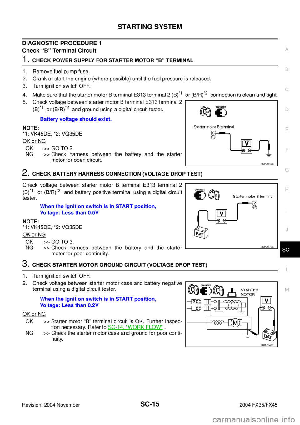
1. CHECK POWER SUPPLY FOR STARTER MOTOR “B” TERMINAL
1. Remove fuel pump fuse.
2. Crank or start the engine (where possible) until the fuel pressure is released.
3. Turn ignition switch OFF.
4. Make sure that the starter motor B terminal E313 terminal 2 (B)
*1 or (B/R)*2 connection is clean and tight.
5. Check voltage between starter motor B terminal E313 terminal 2
(B)
*1 or (B/R)*2 and ground using a digital circuit tester.
NOTE:
*1: VK45DE, *2: VQ35DE
OK or NG
OK >> GO TO 2.
NG >> Check harness between the battery and the starter
motor for open circuit.
2. CHECK BATTERY HARNESS CONNECTION (VOLTAGE DROP TEST)
Check voltage between starter motor B terminal E313 terminal 2
(B)
*1 or (B/R)*2 and battery positive terminal using a digital circuit
tester.
NOTE:
*1: VK45DE, *2: VQ35DE
OK or NG
OK >> GO TO 3.
NG >> Check harness between the battery and the starter
motor for poor continuity.
3. CHECK STARTER MOTOR GROUND CIRCUIT (VOLTAGE DROP TEST)
1. Turn ignition switch OFF.
2. Check voltage between starter motor case and battery negative
terminal using a digital circuit tester.
OK or NG
OK >> Starter motor “B” terminal circuit is OK. Further inspec-
tion necessary. Refer to SC-14, "
WORK FLOW" .
NG >> Check the starter motor case and ground for poor conti-
nuity. Battery voltage should exist.
PKIA2842E
When the ignition switch is in START position,
Voltage: Less than 0.5V
PKIA2370E
When the ignition switch is in START position,
Voltage: Less than 0.2V
PKIA2943E
Page 4105 of 4449

SC-16
STARTING SYSTEM
Revision: 2004 November 2004 FX35/FX45
DIAGNOSTIC PROCEDURE 2
Check “S” Connector Circuit
1. CHECK POWER SUPPLY FOR STARTER MOTOR “S” CONNECTOR
1. Remove fuel pump fuse.
2. Crank or start the engine (where possible) until the fuel pressure is released.
3. Turn ignition switch OFF.
4. Disconnect starter motor S connector.
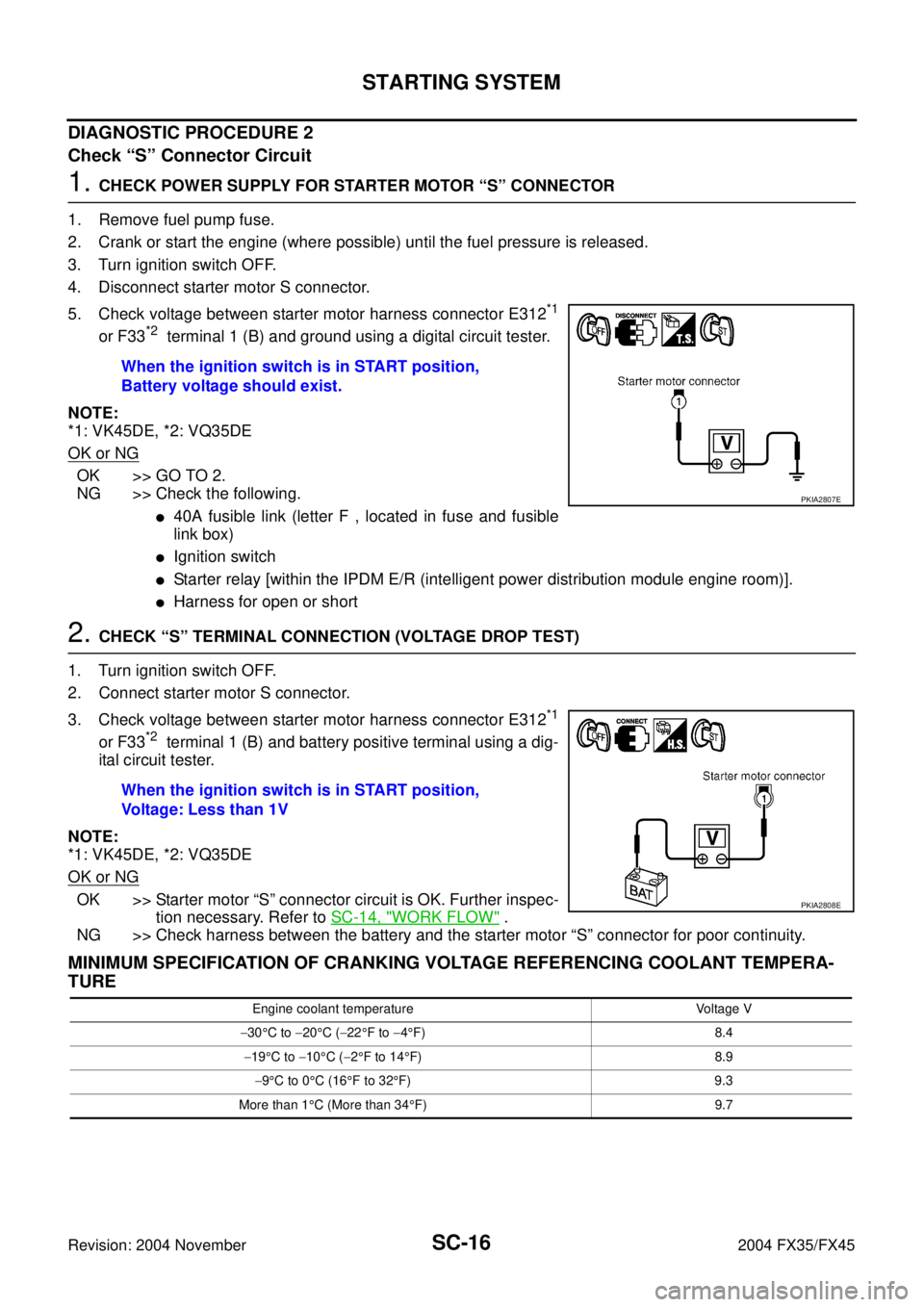
5. Check voltage between starter motor harness connector E312
*1
or F33*2 terminal 1 (B) and ground using a digital circuit tester.
NOTE:
*1: VK45DE, *2: VQ35DE
OK or NG
OK >> GO TO 2.
NG >> Check the following.
�40A fusible link (letter F , located in fuse and fusible
link box)
�Ignition switch
�Starter relay [within the IPDM E/R (intelligent power distribution module engine room)].
�Harness for open or short
2. CHECK “S” TERMINAL CONNECTION (VOLTAGE DROP TEST)
1. Turn ignition switch OFF.
2. Connect starter motor S connector.
3. Check voltage between starter motor harness connector E312
*1
or F33*2 terminal 1 (B) and battery positive terminal using a dig-
ital circuit tester.
NOTE:
*1: VK45DE, *2: VQ35DE
OK or NG
OK >> Starter motor “S” connector circuit is OK. Further inspec-
tion necessary. Refer to SC-14, "
WORK FLOW" .
NG >> Check harness between the battery and the starter motor “S” connector for poor continuity.
MINIMUM SPECIFICATION OF CRANKING VOLTAGE REFERENCING COOLANT TEMPERA-
TURE
When the ignition switch is in START position,
Battery voltage should exist.
PKIA2807E
When the ignition switch is in START position,
Voltage: Less than 1V
PKIA2808E
Engine coolant temperature Voltage V
−30°C to −20°C (−22°F to −4°F) 8.4
−19°C to −10°C (−2°F to 14°F) 8.9
−9°C to 0°C (16°F to 32°F) 9.3
More than 1°C (More than 34°F) 9.7