Page 4075 of 4449
RSU-16
STABILIZER BAR
Revision: 2004 November 2004 FX35/FX45
STABILIZER BARPFP:56230
Removal and InstallationAES000MT
REMOVAL
1. Remove center muffler from vehicle. Refer to EX-3, "Removal and Installation" .
2. Remove fixing bolts and remove stabilizer connecting rod mount bracket from suspension arm with power
tool.
3. Remove lower side fixing nut on stabilizer connecting rod and remove stabilizer connecting rod from stabi-
lizer bar with power tool.
4. Remove fixing nuts on stabilizer clamps and remove stabilizer from vehicle with power tool.
INSPECTION AFTER REMOVAL
Check stabilizer bar, stabilizer bushings, stabilizer clamps, stabilizer connecting rod, stabilizer connecting rod
mounting bracket for any deformation, cracks or damage. Replace if necessary.
INSTALLATION
�Refer to RSU-7, "Components" for tightening torque. Install in the reverse order of removal.
NOTE:
Refer to component parts location and do not reuse non-reusable parts.
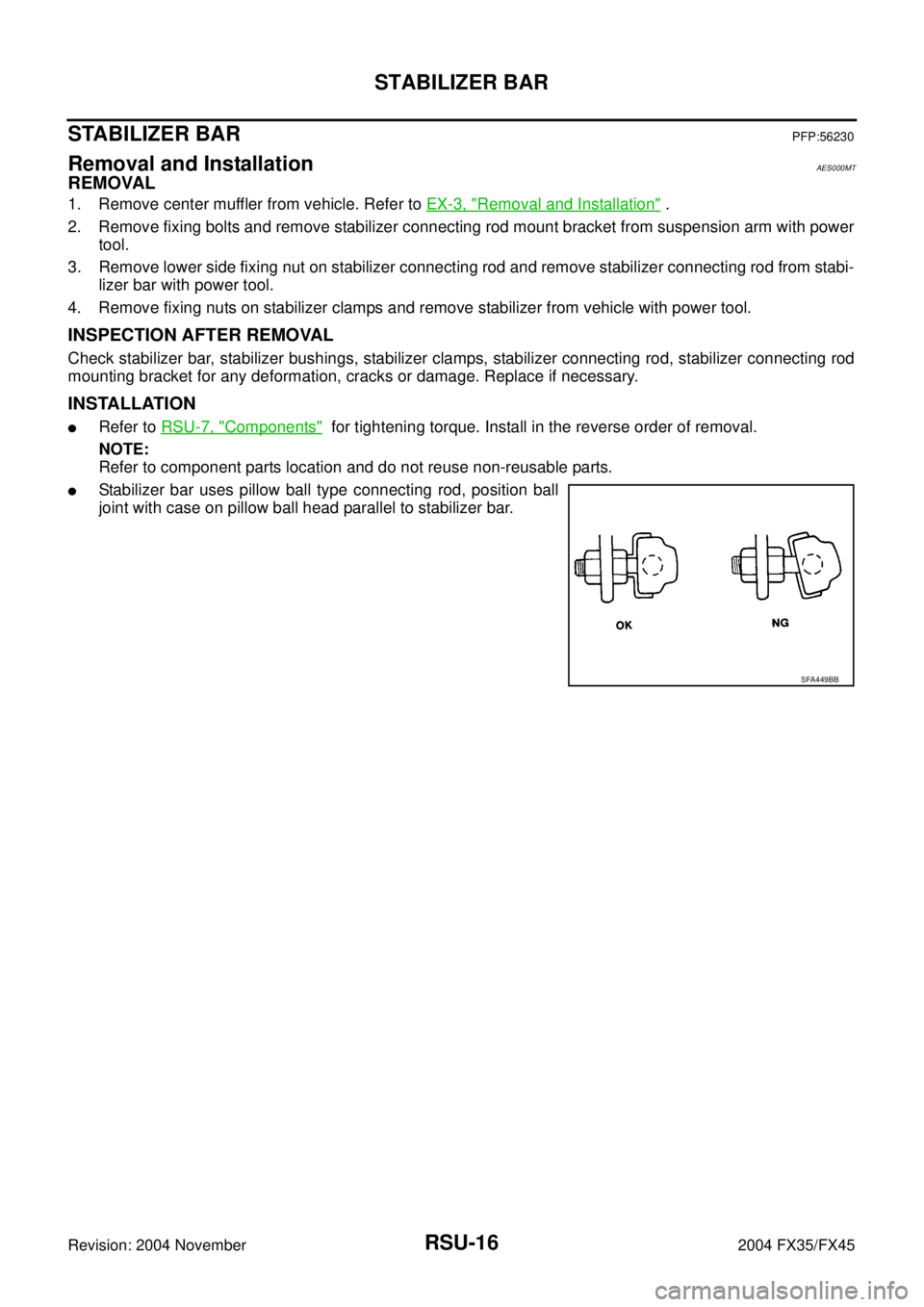
�Stabilizer bar uses pillow ball type connecting rod, position ball
joint with case on pillow ball head parallel to stabilizer bar.
SFA449BB
Page 4076 of 4449
REAR SUSPENSION MEMBER
RSU-17
C
D
F
G
H
I
J
K
L
MA
B
RSU
Revision: 2004 November 2004 FX35/FX45
REAR SUSPENSION MEMBERPFP:55501
Removal and InstallationAES000MU
REMOVAL
1. Remove tire with power tool.
2. Remove brake caliper with power tool. Hang it in a place where it will not interfere with work. Refer toBR-
25, "REAR DISC BRAKE" .
NOTE:
Avoid depressing brake pedal while brake caliper is removed.
3. Remove wheel sensor from rear final drive, then remove wheel sensor harness from rear suspension
member. Refer to BRC-57, "
WHEEL SENSORS" .
4. Remove center muffler and main muffler. Refer to EX-3, "
EXHAUST SYSTEM" .
5. Remove stabilizer bar. Refer to RSU-16, "
Removal and Installation" .
6. Remove rear drive shaft. Refer to RAX-9, "
REAR DRIVE SHAFT" .
7. Remove rear final drive. Refer to RFD-11, "
REAR FINAL DRIVE ASSEMBLY" .
8. Separate attachments between parking brake cable and vehicle and rear suspension member. Refer to
PB-3, "
PARKING BRAKE CONTROL" .
9. Remove rear lower link and coil spring. Refer to RSU-15, "
Removal and Installation" .
10. Remove fixing bolt in lower side of shock absorber with power tool.
11. Set jack under rear suspension member.
12. Remove fixing bolts and nuts of tunnel stay and member stay with power tool, then remove those parts
from vehicle.
13. Remove fixing bolts and nuts of rear pin stay with power tool and then remove rear pin stay from vehicle.
14. Slowly lowering jack, then remove rear suspension member, suspension arm, radius rod, front lower link
and axle from vehicle as a unit.
15. Remove fixing bolts and nuts with power tool, then remove suspension arm, front lower link, and radius
rod from rear suspension member.
INSPECTION AFTER REMOVAL
Check rear suspension member for deformation, cracks, and other damage and replace if necessary.
INSTALLATION
�Refer to RSU-7, "Components" , for tightening torque. Install in the reverse order of removal.
NOTE:
Refer to component parts location and do not reuse non-reusable parts.
�Perform final tightening of installation position of links (rubber bushing) under unladen conditions with tires
on level ground. Check wheel alignment. Refer to RSU-5, "
Wheel Alignment Inspection" .
�After adjusting wheel alignment, adjust neutral position of steering angle sensor. Refer to BRC-6, "Adjust-
ment of Steering Angle Sensor Neutral Position" .
Page 4091 of 4449
SC-2
PRECAUTIONS
Revision: 2004 November 2004 FX35/FX45
PRECAUTIONSPFP:00001
Precautions for Supplemental Restraint System (SRS) “AIR BAG” and “SEAT
BELT PRE-TENSIONER”
AKS00794
The Supplemental Restraint System such as “AIR BAG” and “SEAT BELT PRE-TENSIONER”, used along
with a front seat belt, helps to reduce the risk or severity of injury to the driver and front passenger for certain
types of collision. This system includes seat belt switch inputs and dual stage front air bag modules. The SRS
system uses the seat belt switches to determine the front air bag deployment, and may only deploy one front
air bag, depending on the severity of a collision and whether the front occupants are belted or unbelted.
Information necessary to service the system safely is included in the SRS and SB section of this Service Man-
ual.
WARNING:
�To avoid rendering the SRS inoperative, which could increase the risk of personal injury or death
in the event of a collision which would result in air bag inflation, all maintenance must be per-
formed by an authorized NISSAN/INFINITI dealer.
�Improper maintenance, including incorrect removal and installation of the SRS, can lead to per-
sonal injury caused by unintentional activation of the system. For removal of Spiral Cable and Air
Bag Module, see the SRS section.
�Do not use electrical test equipment on any circuit related to the SRS unless instructed to in this
Service Manual. SRS wiring harnesses can be identified by yellow and/or orange harnesses or
harness connectors.
Wiring Diagrams and Trouble DiagnosisAKS00796
When you read wiring diagrams, refer to the following:
� Refer to GI-15, "How to Read Wiring Diagrams" in GI section.
� Refer to PG-3, "POWER SUPPLY ROUTING CIRCUIT" for power distribution circuit in PG section.
When you perform trouble diagnosis, refer to the following:
�Refer to GI-11, "HOW TO FOLLOW TEST GROUPS IN TROUBLE DIAGNOSES" in GI section.
�Refer to GI-27, "How to Perform Efficient Diagnosis for an Electrical Incident" in GI section.
Page 4092 of 4449
PREPARATION
SC-3
C
D
E
F
G
H
I
J
L
MA
B
SC
Revision: 2004 November 2004 FX35/FX45
PREPARATIONPFP:00002
Special Service ToolsAKS00797
Commercial Service ToolsAKS00798
Tool number
Tool nameDescription
J-44373 Model 620
Battery/Starting/Charging system
tester
SEL403X
Tool number
Tool nameDescription
Power toolLoosening bolts and nuts
PBIC0190E
Page 4099 of 4449

SC-10
STARTING SYSTEM
Revision: 2004 November 2004 FX35/FX45
STARTING SYSTEMPFP:23300
System Description AKS0079C
Power is supplied at all times:
�through 40A fusible link (letter F, located in the fuse and fusible link box)
�to ignition switch terminal 1
�through 15A fuse (No. 78, located in the IPDM E/R)
�to CPU of IPDM E/R
�through 10A fuse (No. 71, located in the IPDM E/R)
�to CPU of IPDM E/R.
When the selector lever in the P or N position, power is supplied:
�from TCM, and through A/T assembly terminal 9
�to IPDM E/R terminal 53.
Ground is supplied:
�to IPDM E/R terminals 38, 50 and 60
�from body grounds E21, E50 and E51.
With the ignition switch in the START position, and provided that the IPDM E/R receives a starter relay ON sig-
nal from the CAN lines, the IPDM E/R is energized and power is supplied:
�from ignition switch terminal 5
�to IPDM E/R terminal 4 and
�through IPDM E/R terminal 3
�to starter motor terminal 1.
The starter motor plunger closes and provides a closed circuit between the battery and starter motor. The
starter motor is grounded to the engine block. With power and ground supplied, cranking occurs and the
engine starts.
Page 4104 of 4449
STARTING SYSTEM
SC-15
C
D
E
F
G
H
I
J
L
MA
B
SC
Revision: 2004 November 2004 FX35/FX45
DIAGNOSTIC PROCEDURE 1
Check “B” Terminal Circuit
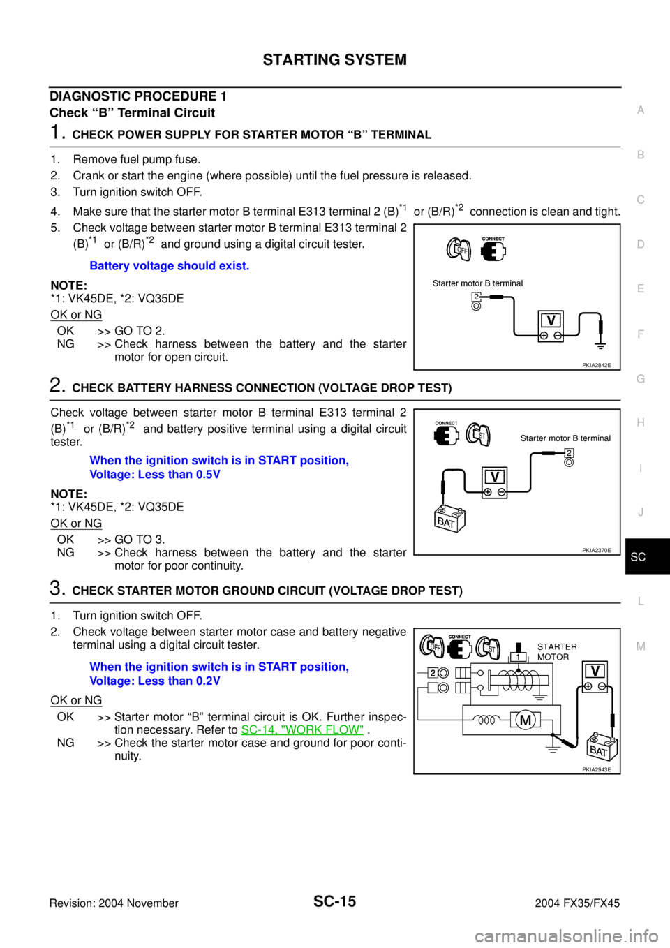
1. CHECK POWER SUPPLY FOR STARTER MOTOR “B” TERMINAL
1. Remove fuel pump fuse.
2. Crank or start the engine (where possible) until the fuel pressure is released.
3. Turn ignition switch OFF.
4. Make sure that the starter motor B terminal E313 terminal 2 (B)
*1 or (B/R)*2 connection is clean and tight.
5. Check voltage between starter motor B terminal E313 terminal 2
(B)
*1 or (B/R)*2 and ground using a digital circuit tester.
NOTE:
*1: VK45DE, *2: VQ35DE
OK or NG
OK >> GO TO 2.
NG >> Check harness between the battery and the starter
motor for open circuit.
2. CHECK BATTERY HARNESS CONNECTION (VOLTAGE DROP TEST)
Check voltage between starter motor B terminal E313 terminal 2
(B)
*1 or (B/R)*2 and battery positive terminal using a digital circuit
tester.
NOTE:
*1: VK45DE, *2: VQ35DE
OK or NG
OK >> GO TO 3.
NG >> Check harness between the battery and the starter
motor for poor continuity.
3. CHECK STARTER MOTOR GROUND CIRCUIT (VOLTAGE DROP TEST)
1. Turn ignition switch OFF.
2. Check voltage between starter motor case and battery negative
terminal using a digital circuit tester.
OK or NG
OK >> Starter motor “B” terminal circuit is OK. Further inspec-
tion necessary. Refer to SC-14, "
WORK FLOW" .
NG >> Check the starter motor case and ground for poor conti-
nuity. Battery voltage should exist.
PKIA2842E
When the ignition switch is in START position,
Voltage: Less than 0.5V
PKIA2370E
When the ignition switch is in START position,
Voltage: Less than 0.2V
PKIA2943E
Page 4105 of 4449
SC-16
STARTING SYSTEM
Revision: 2004 November 2004 FX35/FX45
DIAGNOSTIC PROCEDURE 2
Check “S” Connector Circuit
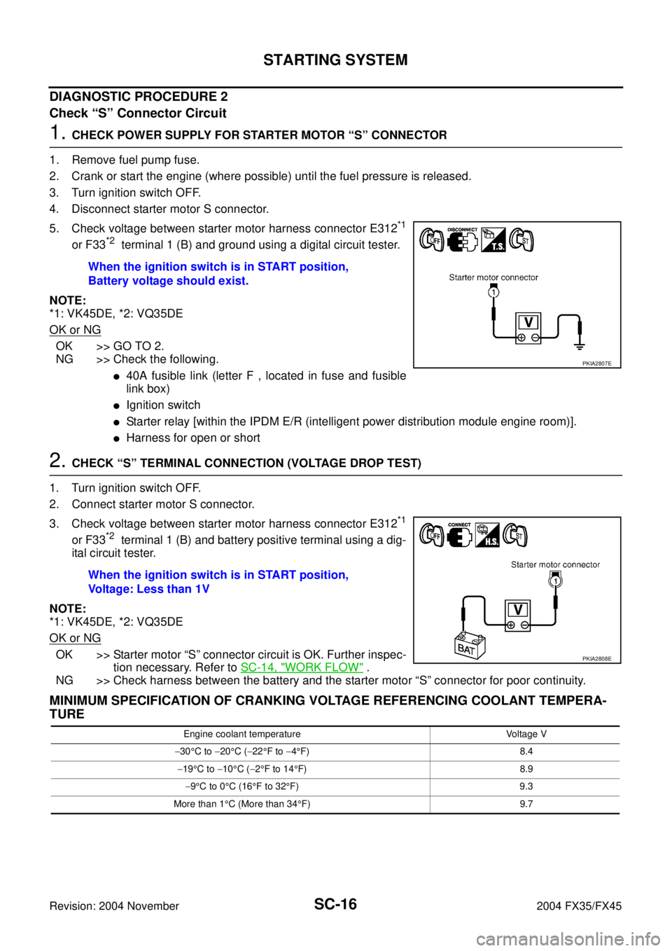
1. CHECK POWER SUPPLY FOR STARTER MOTOR “S” CONNECTOR
1. Remove fuel pump fuse.
2. Crank or start the engine (where possible) until the fuel pressure is released.
3. Turn ignition switch OFF.
4. Disconnect starter motor S connector.
5. Check voltage between starter motor harness connector E312
*1
or F33*2 terminal 1 (B) and ground using a digital circuit tester.
NOTE:
*1: VK45DE, *2: VQ35DE
OK or NG
OK >> GO TO 2.
NG >> Check the following.
�40A fusible link (letter F , located in fuse and fusible
link box)
�Ignition switch
�Starter relay [within the IPDM E/R (intelligent power distribution module engine room)].
�Harness for open or short
2. CHECK “S” TERMINAL CONNECTION (VOLTAGE DROP TEST)
1. Turn ignition switch OFF.
2. Connect starter motor S connector.
3. Check voltage between starter motor harness connector E312
*1
or F33*2 terminal 1 (B) and battery positive terminal using a dig-
ital circuit tester.
NOTE:
*1: VK45DE, *2: VQ35DE
OK or NG
OK >> Starter motor “S” connector circuit is OK. Further inspec-
tion necessary. Refer to SC-14, "
WORK FLOW" .
NG >> Check harness between the battery and the starter motor “S” connector for poor continuity.
MINIMUM SPECIFICATION OF CRANKING VOLTAGE REFERENCING COOLANT TEMPERA-
TURE
When the ignition switch is in START position,
Battery voltage should exist.
PKIA2807E
When the ignition switch is in START position,
Voltage: Less than 1V
PKIA2808E
Engine coolant temperature Voltage V
−30°C to −20°C (−22°F to −4°F) 8.4
−19°C to −10°C (−2°F to 14°F) 8.9
−9°C to 0°C (16°F to 32°F) 9.3
More than 1°C (More than 34°F) 9.7
Page 4106 of 4449
STARTING SYSTEM
SC-17
C
D
E
F
G
H
I
J
L
MA
B
SC
Revision: 2004 November 2004 FX35/FX45
Removal and Installation AKS00BQ1
VK45DE ENGINE MODELS
Removal
1. Disconnect negative battery cable.
2. Remove engine front and rear undercover, using power tools.
3. Disconnect S connector.
4. Remove B terminal nut.
5. Remove starter motor mounting bolts.
6. Loosen A/T fluid cooler tube clip bolts. Refer to AT- 2 6 6 ,
"TRANSMISSION ASSEMBLY" in “AUTOMATIC TRANSMIS-
SION (A/T)” section.
7. Remove starter motor to the direction of under side the vehicle.
Installation
Install in the reverse order of removal.
CAUTION:
Be sure to tighten B terminal nut carefully.
1. Starter motor 2. Starter motor mounting bolt 3. B terminal harness
4. B terminal nut 5. S connector 6. Cylinder block
PKIA2809E
PKIA2810E